EP0868216B1 - A decanter centrifuge - Google Patents
A decanter centrifuge Download PDFInfo
- Publication number
- EP0868216B1 EP0868216B1 EP96943019A EP96943019A EP0868216B1 EP 0868216 B1 EP0868216 B1 EP 0868216B1 EP 96943019 A EP96943019 A EP 96943019A EP 96943019 A EP96943019 A EP 96943019A EP 0868216 B1 EP0868216 B1 EP 0868216B1
- Authority
- EP
- European Patent Office
- Prior art keywords
- baffle
- screw
- conveyor
- heavy phase
- bowl
- Prior art date
- Legal status (The legal status is an assumption and is not a legal conclusion. Google has not performed a legal analysis and makes no representation as to the accuracy of the status listed.)
- Expired - Lifetime
Links
- 239000000463 material Substances 0.000 claims abstract description 5
- 230000010006 flight Effects 0.000 claims description 23
- 238000011144 upstream manufacturing Methods 0.000 claims description 15
- 238000000926 separation method Methods 0.000 claims description 4
- 230000003247 decreasing effect Effects 0.000 claims description 2
- 230000004323 axial length Effects 0.000 abstract 1
- 230000014759 maintenance of location Effects 0.000 abstract 1
- 238000009825 accumulation Methods 0.000 description 7
- 230000001154 acute effect Effects 0.000 description 6
- 230000000694 effects Effects 0.000 description 4
- 230000002093 peripheral effect Effects 0.000 description 4
- 230000007704 transition Effects 0.000 description 3
- 230000004888 barrier function Effects 0.000 description 2
- 230000009467 reduction Effects 0.000 description 2
- 230000009471 action Effects 0.000 description 1
- 230000008901 benefit Effects 0.000 description 1
- 230000001771 impaired effect Effects 0.000 description 1
- 239000012535 impurity Substances 0.000 description 1
- 239000007788 liquid Substances 0.000 description 1
- 230000033001 locomotion Effects 0.000 description 1
- 238000000034 method Methods 0.000 description 1
- 239000002245 particle Substances 0.000 description 1
- 230000008569 process Effects 0.000 description 1
- 239000002002 slurry Substances 0.000 description 1
- 239000000126 substance Substances 0.000 description 1
- 238000003466 welding Methods 0.000 description 1
Images


Classifications
-
- B—PERFORMING OPERATIONS; TRANSPORTING
- B04—CENTRIFUGAL APPARATUS OR MACHINES FOR CARRYING-OUT PHYSICAL OR CHEMICAL PROCESSES
- B04B—CENTRIFUGES
- B04B1/00—Centrifuges with rotary bowls provided with solid jackets for separating predominantly liquid mixtures with or without solid particles
- B04B1/20—Centrifuges with rotary bowls provided with solid jackets for separating predominantly liquid mixtures with or without solid particles discharging solid particles from the bowl by a conveying screw coaxial with the bowl axis and rotating relatively to the bowl
- B04B2001/2041—Centrifuges with rotary bowls provided with solid jackets for separating predominantly liquid mixtures with or without solid particles discharging solid particles from the bowl by a conveying screw coaxial with the bowl axis and rotating relatively to the bowl with baffles, plates, vanes or discs attached to the conveying screw
Definitions
- the present invention relates to a decanter centrifuge for separation of a material supplied into a light phase and a heavy phase, comprising an elongated bowl adapted for rotation about its longitudinal axis, a screw conveyor arranged in the bowl and coaxial therewith and comprising a body carrying a screw, inlet ports in the screw conveyor for supply of the material to be separated, and discharge ports for the heavy phase in the bowl at one end of the conveyor, the screw conveyor being adapted to rotate in relation to the bowl for transporting the heavy phase towards the discharge ports for the heavy phase, and a baffle which is arranged between the inlet ports and the discharge ports and the radial extent of which in any axial position is smaller than the radial extent of the screw in the same axial position, the baffle extending from a position on the side of a flight of the screw of the conveyer facing towards the discharge ports to a position on the side facing away from the discharge ports of one of the flights of the conveyor screw following in the direction towards the discharge ports, without intersecting an intermediate flight.
- US patent specication No. 3,885,734 describes a centrifuge of this type, which has a baffle in the form of an annular disc arranged at right angles to the longitudinal axis of the conveyor, The baffle functions as a barrier preventing the light phase from moving towards the discharge openings for the heavy phase. With this barrier the decanter can be operated with unequal liquid levels on the light phase side and the heavy phase side of the baffle disc.
- the heavy phase is transported by the screw conveyor from the separation chamber constituted by the space between the inner surface of the bowl and the outer surface of the body of the conveyor, to the discharge ports for the heavy phase, and the baffle disc causes a reduction of the cross-sectional area available for this transport.
- this restriction may result in an undesired large accumulation of heavy phase product on the light phase side of the baffle disc and create impaired inlet and separation conditions and in addition increase wear on the decanter as well as require a higher torque to maintain the relative motion between the conveyor and the bowl.
- US patent specification No. 3,934,792 describes a decanter centrifuge of the above mentioned type having a baffle generally in form of a flat, radial plate located across the helical chamber bounded by two adjacent screw flights, the outer surface of the conveyor body and the inner surface of the bowl.
- This baffle has the same disadvantages as the baffle known from US 3,885,734 and because of its short length it reduces the cross-sectional area available for transport of the heavy phase to the discharge ports even more than the above mentioned prior art baffle.
- the baffle has a further disadvantage in that it does not have the same hand as the screw conveyor and therefore counteracts the transporting effect of the flights of the screw conveyor.
- the baffle As the baffle is shaped like a helical rib handed in the same direction as the conveyor screw, it actively contributes to transporting the heavy phase towards the discharge openings in the same way as the screw, whereby the accumulation of the heavy phase on the upstream side of the baffle is reduced, the effect of which is that the disadvantages described above, caused by the accumulation, are reduced or completely eliminated.
- the baffle according to the invention has the added advantage that the transport area under the baffle can be increased in relation to the prior-art baffles by maintaining the same gap and extending the baffle over more than 360° of the circumference of the conveyor, thus giving it an axial extent longer than seen in prior art.
- the baffle according to the invention also solves two problems existing in the prior-art baffles.
- the first problem is that in the area where the side of the flight of the screw facing towards the discharge ports, in the following called the downstream side, meets the baffle, a large accumulation of the heavy phase often occurs on the side of the baffle facing away from the discharge ports, in the following called the upstream side, which is due to the fact that the friction between the heavy phase and the outer wall of the bowl drives the heavy phase into the corner that is created between said surfaces.
- This excess of heavy phase can only get away in one way, viz., under the peripheral edge of the baffle where, however, the transport area is restricted, seen in relation to the large quantity of heavy phase.
- the second problem of the prior-art baffles is that in the area where the upstream side of the flight of the screw meets the baffle, a shortage of heavy phase often arises on the upstream side of the baffle, because as mentioned above, the heavy phase has been accumulated in the corner between the downstream side of the flight of the screw and the upstream side of the baffle.
- This shortage of heavy phase causes the light phase in said area to penetrate under the periphery of the baffle and become mixed with the heavy phase already separated which is being transported by the screw towards the discharge ports for the heavy phase.
- the baffle may have a steadily increasing or decreasing pitch. By changing the pitch of the baffle, the transport capability of the baffle can be varied as desired.
- the baffle may have a constant pitch. This is especially suitable when the screw of the conveyor also has a constant pitch, as this prevents the spaces between the baffle and the adjacent screw flights from becoming too narrow.
- the enveloping surface of the baffle may be a conical surface. This renders it possible to vary the gap between the baffle and the inner surface of the bowl. If, for example, the baffle is arranged at the conical section of the bowl, and if the enveloping surface of the baffle has an apex angle which is smaller than the apex angle of the conical section of the bowl, the gap between the baffle and the bowl will be largest at the end of the baffle facing away from the discharge ports for the heavy phase and will be reduced in a linear manner towards the opposite end of the baffle.
- the distance from the axis of rotation to the periphery of the baffle is also reduced in a direction towards the discharge ports although the gap is reduced. This causes large heavy phase particles and firmly compressed heavy phase to pass under the periphery of the baffle where the gap is largest, while less compressed heavy phase will be transported by the baffle towards the upstream side of the next screw flight and will thus protect against break-through of light phase also at the smallest radius to the peripheral edge of the baffle.
- the baffle can at each joint with the flights of the screw have a section substantially at right angles to the surface of the flight.
- the joining section of the baffle can at at least one of the baffle ends, seen in a section at right angles to the longitudinal axis of the conveyor, be inclined so that the radially outermost part of the section is upstream of the radially innermost part seen in relation to the rotational direction of the conveyor in relation to the bowl.
- conveyors with several grooves may have a baffle in each groove, and the design and position of the baffle may be the same in each groove, To avoid break-through of light phase in one of the grooves, each flight must have a baffle, and to avoid large centrifugal forces it is suitable for all baffles to be designed and arranged in the same manner in each groove.
- the thickness of the baffle may be from 0.05 to 0.5 times the lead of the conveyor screw, preferably from 0.1 to 0.2 times the lead, especially 0.15 times the lead, or the thickness may be from 0.8 to 1.5 times the thickness of the screw flights, preferably 1.0 times the thickness of the screw flights, Increasing the thickness of the baffle achieves an increase in the frictional force between the heavy phase and the inner surface of the bowl, which results in an increase of the heavy phase quantity on the upstream side of the baffle.
- the thickness of the baffle it is possible to adapt the centrifuge according to the invention better to certain operational conditions.
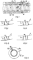
- the decanter centrifuge in Fig. 1 has a bowl 2 with a screw conveyor 3 having a cylindrical body 4 with a screw 7 and a conical part 5 at one end.
- the conveyor 3 has inlet ports 6 for the substance to be separated, and the bowl 2 has discharge ports 14 for the separated heavy phase.
- the light phase 12 is close to the body of the conveyor, while the heavy phase 13 is located at the inner surface of the bowl.
- the light phase is drained away over an outlet weir 10 on the bowl.
- the heavy phase is carried by the screw 7 towards the discharge ports 14 in the bowl at its conical end.
- the figure shows a prior-art baffle consisting of an annular disc 8 arranged at right angles to the longitudinal axis of the conveyor.
- the centrifuge in Fig. 2 has a baffle 8a according to the invention where all of the baffle is located on the conical part 5 of the conveyor,
- the baffle 8a extends over an angle of 360°.
- the enveloping surface of the baffle is a cone with an apex angle smaller than the apex angle of the conical part 5 so that the gap between the periphery of the baffle and the inner surface of the bowl is larger at the end of the baffle facing away from the discharge ports 14 than at the opposite end.
- Fig. 3 shows a baffle 8b arranged on the cylindrical part of the conveyor, As indicated by the dashed line 15b, the enveloping surface of the baffle is a conical surface opening towards the conical part of the conveyor.
- the baffle in Fig. 4 extends over 360° and extends over the transition between the cylindrical and conical parts of the conveyor. As indicated by the dashed line 15c, the gap between the periphery of the baffle and the inner surface of the bowl is kept constant in the cylindrical part of the bowl, while it is reduced in the conical part of the bowl towards the end with the discharge ports 14.
- the transition between cylinder and cone surface in the enveloping surface of the baffle need not be arranged in the same axial position as the corresponding transition in the enveloping surface for the screw.
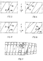
- Fig. 5 shows a baffle 8d extending over 90°.
- the enveloping surface of the baffle is a cone with an apex angle smaller than the apex angle of the conical section of the bowl.
- baffle 8e in Fig. 6 extends over 720°, and the figure illustrates that without any problem baffles of considerable axial extent can be arranged in the centrifuge according to the invention.
- the conveyor illustrated in Fig. 7 has two grooves 17a and 17b with screw flights 7a and 7b. Each of the grooves has inlet ports 6a and 6b. Each groove has a baffle 8f and 8g, respectively. Each baffle extends over about 90°.
- the dashed line 15f indicates that the enveloping surface of the baffle is a conical surface with the same apex angle as the conical section of the bowl.
- the screw flights and the baffle were arranged at right angles to the longitudinal axis of the conveyor.
- the screw flights 7h are arranged at right angles to the longitudinal axis of the conveyor, while the baffle 8h forms and acute angle therewith.
- the baffle 8i which is at right angles to the longitudinal axis of the conveyor, while the screw flights 7i form an acute angle therewith.
- the screw flights 7j and the baffle 8j may, as shown in Fig. 10, be mutually parallel and form an acute angle with the longitudinal axis of the conveyor.
- baffle 8k can be at right angles to the longitudinal axis of the conveyor, while the screw flights 7k form an obtuse angle therewith.
- Figs. 8-10 clearly illustrate that a helical baffle can be used without any problem together with a screw, known per se , with inclined, so-called 'canted' flights.
- the baffle 8a shown in Fig. 12 has a section 16a at right angles to a surface of a screw flight, not shown, while the section itself extends radially, as seen in cross-section.
- its end section is also at right angles to the pertaining screw flight, but is inclined in such a manner that heavy phase passed in between the baffle and the screw can easily escape under the peripheral edge of the baffle when it meets this end section, so as to prevent heavy phase from accumulating at this place as explained in further detail below with reference to Figs. 15 and 16.
- only one end section of the baffle is inclined, but the inclination can also be used at both end sections.
- the rotational direction of the conveyor in relation to the bowl is indicated by the arrow 18 in the drawing.
- Figs. 13-16 schematically show an developed section of the conveyor with the location of a screw flight and a baffle.
- the transport direction of the screw is indicated by the arrow s.
- the direction of the frictional force from the bowl affecting the heavy phase is indicated by the arrow f.
- the batching in Fig. 13 indicates an area 20 which is located at the place where the downstream side of a flight 7m meets a prior-art baffle disc 8m. It can be seen that the flight will try to press the heavy phase in the direction of the arrow s, while the frictional force will try to press the heavy phase in the direction of the arrow f. The result is that an accumulation of heavy phase occurs in the area 20.
- Fig. 14 shows the corresponding area 21 in a centrifuge according to the invention where the downstream side of a flight 7n meets a baffle 8n.
- this area 21 the combined action of the flight 7n and the frictional force f will pass the heavy phase along the downstream side of the baffle 8n, from where the heavy phase owing to the baffle being shaped as a helical surface is easily transported on and at the same time flowing under the baffle.
- Fig. 15 shows an area 22 located at the place where the upstream side of a flight 7m meets a known baffle disc 8m.
- the area 22 there is a tendency for a shortage of heavy phase to arise, because the existing heavy phase partly is pulled away in the direction f of the frictional force, partly can easily escape in the direction s under the periphery of the baffle disc, while the flight 7m in connection with the baffle plate 8m, as explained above with reference to Fig. 13, blocks the supply of new heavy phase.
- the effect of this is that the light phase can penetrate under the periphery of the baffle disc, whereby light phase and heavy phase are mixed together on the heavy phase side of the baffle disc.
- the baffle 8n has a thickness corresponding to 0.15 times the lead of the flight 7.
Landscapes
- Centrifugal Separators (AREA)
Applications Claiming Priority (3)
| Application Number | Priority Date | Filing Date | Title |
|---|---|---|---|
| DK143295A DK143295A (da) | 1995-12-18 | 1995-12-18 | Dekantercentrifuge |
| DK143295 | 1995-12-18 | ||
| PCT/DK1996/000544 WO1997022411A1 (en) | 1995-12-18 | 1996-12-18 | A decanter centrifuge |
Publications (2)
| Publication Number | Publication Date |
|---|---|
| EP0868216A1 EP0868216A1 (en) | 1998-10-07 |
| EP0868216B1 true EP0868216B1 (en) | 1999-12-01 |
Family
ID=8104776
Family Applications (1)
| Application Number | Title | Priority Date | Filing Date |
|---|---|---|---|
| EP96943019A Expired - Lifetime EP0868216B1 (en) | 1995-12-18 | 1996-12-18 | A decanter centrifuge |
Country Status (19)
| Country | Link |
|---|---|
| US (1) | US6024686A (da) |
| EP (1) | EP0868216B1 (da) |
| JP (1) | JP4267069B2 (da) |
| KR (1) | KR100472783B1 (da) |
| CN (1) | CN1082839C (da) |
| AT (1) | ATE187101T1 (da) |
| AU (1) | AU708860B2 (da) |
| BR (1) | BR9612052A (da) |
| DE (1) | DE69605448T2 (da) |
| DK (1) | DK143295A (da) |
| EE (1) | EE03339B1 (da) |
| ES (1) | ES2142103T3 (da) |
| GR (1) | GR3032750T3 (da) |
| NO (1) | NO311559B1 (da) |
| NZ (1) | NZ324672A (da) |
| PL (1) | PL181374B1 (da) |
| PT (1) | PT868216E (da) |
| RU (1) | RU2181075C2 (da) |
| WO (1) | WO1997022411A1 (da) |
Families Citing this family (21)
| Publication number | Priority date | Publication date | Assignee | Title |
|---|---|---|---|---|
| US6572524B1 (en) * | 2000-07-14 | 2003-06-03 | Alfa Laval Inc. | Decanter centrifuge having a heavy phase solids baffle |
| DK200200598A (da) * | 2002-04-22 | 2003-10-23 | Alfa Laval Copenhagen As | Dekantercentrifuge |
| US20040138040A1 (en) * | 2003-01-15 | 2004-07-15 | Hensley Gary L. | Decanter centrifuge control |
| SE525413C2 (sv) * | 2003-06-18 | 2005-02-15 | Alfa Laval Corp Ab | En skruvtransportör för en dekantercentrifug |
| US20050054506A1 (en) * | 2003-07-30 | 2005-03-10 | Bradley Bruce J. | Microbial concentration system |
| RU2258565C1 (ru) * | 2004-05-05 | 2005-08-20 | Государственное образовательное учреждение высшего профессионального образования Воронежская государственная технологическая академия | Шнековая центрифуга |
| ATE524238T1 (de) * | 2005-06-23 | 2011-09-15 | Westrup As | Dekanterzentrifuge |
| DE102005061461A1 (de) * | 2005-12-22 | 2007-07-05 | Westfalia Separator Ag | Vollmantel-Schneckenzentrifuge |
| DE102007003928A1 (de) * | 2007-01-26 | 2008-08-07 | Westfalia Separator Gmbh | Vollmantel-Schneckenzentrifuge mit einer Stauscheibe |
| DE102009001054A1 (de) * | 2009-02-20 | 2010-09-02 | Hiller Gmbh | Vollmantel-Schneckenzentrifuge mit Grobstoff-Auslass |
| RU2417844C1 (ru) * | 2009-10-22 | 2011-05-10 | Алексей Георгиевич Трошин | Центрифуга с непрерывной выгрузкой осадка |
| CN102716816A (zh) * | 2012-06-20 | 2012-10-10 | 江苏博威铸业集团有限公司 | 一种螺旋卸料沉降离心机 |
| DK177710B1 (da) * | 2012-09-14 | 2014-03-31 | Alfa Laval Corp Ab | Snegletransportør til en centrifugal separator, navnlig en dekantercentrifuge, og en centrifugal separator |
| KR101389059B1 (ko) * | 2013-05-06 | 2014-04-29 | 주식회사성우 | 원심분리장치 |
| NL2013549B1 (en) * | 2014-09-30 | 2016-10-03 | Marel Townsend Further Proc Bv | Processing apparatus for processing food products using a liquid, assembly and method for processing food products using a liquid. |
| DK3106230T3 (da) * | 2015-06-19 | 2020-04-14 | Andritz Sas | Dekantercentrifuge |
| RU2649448C1 (ru) * | 2017-01-17 | 2018-04-03 | Георгий Петрович Трошин | Центрифуга осадительная |
| RU2656330C1 (ru) * | 2017-07-05 | 2018-06-04 | федеральное государственное бюджетное образовательное учреждение высшего образования "Казанский национальный исследовательский технологический университет" (ФГБОУ ВО "КНИТУ") | Осадительная центрифуга |
| KR102188288B1 (ko) * | 2020-06-11 | 2020-12-09 | 주식회사 화일씨앤이 | 고액분리판으로 탈수효율을 증가시킨 디칸터형 원심탈수기 |
| US11772104B2 (en) * | 2020-06-22 | 2023-10-03 | National Oilwell Varco, L.P. | Decanter centrifuge nozzle |
| RU208975U1 (ru) * | 2021-04-30 | 2022-01-25 | Федеральное государственное бюджетное образовательное учреждение высшего образования "Саратовский государственный технический университет имени Гагарина Ю.А." (СГТУ имени Гагарина Ю.А.) | Шнек центрифуги для разделения суспензий |
Family Cites Families (12)
| Publication number | Priority date | Publication date | Assignee | Title |
|---|---|---|---|---|
| DK111110B (da) * | 1964-04-28 | 1968-06-04 | Thrige Titan As | Centrifuge til separering af væskeblandinger. |
| US3289926A (en) * | 1964-10-14 | 1966-12-06 | Flottweg Motorenwerk Dr Georg | Screw conveyor for a bowl centrifuge |
| SE329128B (da) * | 1966-06-07 | 1970-09-28 | Titan Separator As | |
| US3795361A (en) * | 1972-09-06 | 1974-03-05 | Pennwalt Corp | Centrifuge apparatus |
| AR205952A1 (es) * | 1975-01-03 | 1976-06-15 | Pennwalt Corp | Una centrifuga decantadora |
| JPS5610353A (en) * | 1979-07-05 | 1981-02-02 | Suguru Katsume | Completely-enclosed type screw-carrying centrifugal separator |
| US4245777A (en) * | 1979-08-30 | 1981-01-20 | Pennwalt Corporation | Centrifuge apparatus |
| DE3027020A1 (de) * | 1980-07-17 | 1982-02-04 | Klöckner-Humboldt-Deutz AG, 5000 Köln | Vollmantelzentrifuge zum stoffaustausch zwischen fluessigkeiten |
| US4731182A (en) * | 1985-11-18 | 1988-03-15 | Decanter Pty. Limited | Decanter centrifuge |
| US5653673A (en) * | 1994-06-27 | 1997-08-05 | Amoco Corporation | Wash conduit configuration in a centrifuge apparatus and uses thereof |
| US5509882A (en) * | 1994-09-12 | 1996-04-23 | Tetra Laval Holdings & Finance S.A. | Decanter centrifuge having an offset conveyor flight to aid rinsing |
| US5643169A (en) * | 1995-06-06 | 1997-07-01 | Baker Hughes Incorporated | Decanter centrifuge with adjustable gate control |
-
1995
- 1995-12-18 DK DK143295A patent/DK143295A/da not_active Application Discontinuation
-
1996
- 1996-12-18 KR KR10-1998-0704555A patent/KR100472783B1/ko not_active Expired - Lifetime
- 1996-12-18 EP EP96943019A patent/EP0868216B1/en not_active Expired - Lifetime
- 1996-12-18 PL PL96327605A patent/PL181374B1/pl not_active IP Right Cessation
- 1996-12-18 WO PCT/DK1996/000544 patent/WO1997022411A1/en not_active Ceased
- 1996-12-18 NZ NZ324672A patent/NZ324672A/xx not_active IP Right Cessation
- 1996-12-18 PT PT96943019T patent/PT868216E/pt unknown
- 1996-12-18 EE EE9800177A patent/EE03339B1/xx not_active IP Right Cessation
- 1996-12-18 JP JP52243597A patent/JP4267069B2/ja not_active Expired - Fee Related
- 1996-12-18 AT AT96943019T patent/ATE187101T1/de active
- 1996-12-18 RU RU98113930/13A patent/RU2181075C2/ru not_active IP Right Cessation
- 1996-12-18 AU AU11898/97A patent/AU708860B2/en not_active Ceased
- 1996-12-18 CN CN96199097A patent/CN1082839C/zh not_active Expired - Lifetime
- 1996-12-18 ES ES96943019T patent/ES2142103T3/es not_active Expired - Lifetime
- 1996-12-18 BR BR9612052A patent/BR9612052A/pt not_active IP Right Cessation
- 1996-12-18 US US09/091,155 patent/US6024686A/en not_active Expired - Lifetime
- 1996-12-18 DE DE69605448T patent/DE69605448T2/de not_active Expired - Lifetime
-
1998
- 1998-06-17 NO NO19982797A patent/NO311559B1/no not_active IP Right Cessation
-
2000
- 2000-02-23 GR GR20000400450T patent/GR3032750T3/el unknown
Also Published As
| Publication number | Publication date |
|---|---|
| AU1189897A (en) | 1997-07-14 |
| JP2000501987A (ja) | 2000-02-22 |
| PL181374B1 (pl) | 2001-07-31 |
| US6024686A (en) | 2000-02-15 |
| AU708860B2 (en) | 1999-08-12 |
| PT868216E (pt) | 2000-05-31 |
| BR9612052A (pt) | 1999-02-23 |
| KR100472783B1 (ko) | 2005-05-24 |
| GR3032750T3 (en) | 2000-06-30 |
| NO311559B1 (no) | 2001-12-10 |
| NZ324672A (en) | 1999-11-29 |
| WO1997022411A1 (en) | 1997-06-26 |
| CN1082839C (zh) | 2002-04-17 |
| PL327605A1 (en) | 1998-12-21 |
| DE69605448D1 (de) | 2000-01-05 |
| ES2142103T3 (es) | 2000-04-01 |
| DK143295A (da) | 1997-06-19 |
| DE69605448T2 (de) | 2000-09-07 |
| EE03339B1 (et) | 2001-02-15 |
| NO982797D0 (no) | 1998-06-17 |
| KR20000064430A (ko) | 2000-11-06 |
| NO982797L (no) | 1998-06-17 |
| RU2181075C2 (ru) | 2002-04-10 |
| EP0868216A1 (en) | 1998-10-07 |
| ATE187101T1 (de) | 1999-12-15 |
| JP4267069B2 (ja) | 2009-05-27 |
| CN1205656A (zh) | 1999-01-20 |
Similar Documents
| Publication | Publication Date | Title |
|---|---|---|
| EP0868216B1 (en) | A decanter centrifuge | |
| KR100943692B1 (ko) | 디캔터 원심분리기 | |
| AU701446B2 (en) | Apparatus for filtering plasticized thermoplastics and filter element for an apparatus of this kind | |
| EP0664727B1 (en) | Wear resistant basket for scroll centrifuge | |
| US4519496A (en) | Conveyor screw with wear-resistant members attached to its operative surface | |
| US4540334A (en) | Open-type centrifugal pump with single-blade impeller | |
| US5383617A (en) | Refiner plates with asymmetric inlet pattern | |
| EP0817720B1 (en) | Screw compressor and outlet portion for screw compressor | |
| JPH05202936A (ja) | すべり軸受 | |
| CA2478832C (en) | Decanter centrifuge with wear reinforcement inlet | |
| KR19990078313A (ko) | 분쇄 및 펌프 가능한 물질 분쇄 및 분배장치 | |
| RU98113930A (ru) | Декантирующая центрифуга | |
| CA1206920A (en) | Vortex cleaner | |
| US20060142137A1 (en) | Solid-bowl screw centrifuge | |
| FI110768B (fi) | Putkisyöttimen laite | |
| JP2004504127A (ja) | 重相固形物用のバッフルを有しているデカンタ型の遠心分離機 | |
| CA2240167C (en) | A decanter centrifuge | |
| FI67590C (fi) | Virvelrenare | |
| US4983289A (en) | Screen bowl centrifuge | |
| RU2299168C2 (ru) | Подающая труба для сыпучих продуктов | |
| JP2005334715A (ja) | コニカル部の内周面にグルーブを有するデカンタ型の遠心分離機 | |
| JPS60197252A (ja) | 都市ごみ等の破砕分別装置 |
Legal Events
| Date | Code | Title | Description |
|---|---|---|---|
| PUAI | Public reference made under article 153(3) epc to a published international application that has entered the european phase |
Free format text: ORIGINAL CODE: 0009012 |
|
| 17P | Request for examination filed |
Effective date: 19980605 |
|
| AK | Designated contracting states |
Kind code of ref document: A1 Designated state(s): AT BE CH DE DK ES FI FR GB GR IE IT LI NL PT SE |
|
| GRAG | Despatch of communication of intention to grant |
Free format text: ORIGINAL CODE: EPIDOS AGRA |
|
| 17Q | First examination report despatched |
Effective date: 19990121 |
|
| GRAG | Despatch of communication of intention to grant |
Free format text: ORIGINAL CODE: EPIDOS AGRA |
|
| GRAH | Despatch of communication of intention to grant a patent |
Free format text: ORIGINAL CODE: EPIDOS IGRA |
|
| GRAH | Despatch of communication of intention to grant a patent |
Free format text: ORIGINAL CODE: EPIDOS IGRA |
|
| GRAA | (expected) grant |
Free format text: ORIGINAL CODE: 0009210 |
|
| AK | Designated contracting states |
Kind code of ref document: B1 Designated state(s): AT BE CH DE DK ES FI FR GB GR IE IT LI NL PT SE |
|
| AX | Request for extension of the european patent |
Free format text: LT PAYMENT 19980605;LV PAYMENT 19980605 |
|
| REF | Corresponds to: |
Ref document number: 187101 Country of ref document: AT Date of ref document: 19991215 Kind code of ref document: T |
|
| REG | Reference to a national code |
Ref country code: CH Ref legal event code: EP |
|
| REF | Corresponds to: |
Ref document number: 69605448 Country of ref document: DE Date of ref document: 20000105 |
|
| REG | Reference to a national code |
Ref country code: IE Ref legal event code: FG4D |
|
| ITF | It: translation for a ep patent filed | ||
| REG | Reference to a national code |
Ref country code: CH Ref legal event code: NV Representative=s name: A. BRAUN, BRAUN, HERITIER, ESCHMANN AG PATENTANWAE |
|
| ET | Fr: translation filed | ||
| REG | Reference to a national code |
Ref country code: ES Ref legal event code: FG2A Ref document number: 2142103 Country of ref document: ES Kind code of ref document: T3 |
|
| REG | Reference to a national code |
Ref country code: DK Ref legal event code: T3 |
|
| REG | Reference to a national code |
Ref country code: PT Ref legal event code: SC4A Free format text: AVAILABILITY OF NATIONAL TRANSLATION Effective date: 20000211 |
|
| PLBE | No opposition filed within time limit |
Free format text: ORIGINAL CODE: 0009261 |
|
| STAA | Information on the status of an ep patent application or granted ep patent |
Free format text: STATUS: NO OPPOSITION FILED WITHIN TIME LIMIT |
|
| 26N | No opposition filed | ||
| REG | Reference to a national code |
Ref country code: GB Ref legal event code: IF02 |
|
| REG | Reference to a national code |
Ref country code: CH Ref legal event code: PFA Owner name: ALFA LAVAL SEPARATION A/S Free format text: ALFA LAVAL SEPARATION A/S#MASKINVEJ 5#2860 SOEBORG (DK) -TRANSFER TO- ALFA LAVAL SEPARATION A/S#MASKINVEJ 5#2860 SOEBORG (DK) |
|
| PGFP | Annual fee paid to national office [announced via postgrant information from national office to epo] |
Ref country code: AT Payment date: 20101222 Year of fee payment: 15 |
|
| PGFP | Annual fee paid to national office [announced via postgrant information from national office to epo] |
Ref country code: SE Payment date: 20111213 Year of fee payment: 16 Ref country code: CH Payment date: 20111213 Year of fee payment: 16 Ref country code: IE Payment date: 20111212 Year of fee payment: 16 Ref country code: NL Payment date: 20111220 Year of fee payment: 16 Ref country code: FI Payment date: 20111212 Year of fee payment: 16 |
|
| PGFP | Annual fee paid to national office [announced via postgrant information from national office to epo] |
Ref country code: BE Payment date: 20111229 Year of fee payment: 16 |
|
| BERE | Be: lapsed |
Owner name: *ALFA LAVAL SEPARATION A/S Effective date: 20121231 |
|
| REG | Reference to a national code |
Ref country code: NL Ref legal event code: V1 Effective date: 20130701 |
|
| REG | Reference to a national code |
Ref country code: LT Ref legal event code: MM9D Effective date: 20121218 |
|
| PG25 | Lapsed in a contracting state [announced via postgrant information from national office to epo] |
Ref country code: SE Free format text: LAPSE BECAUSE OF NON-PAYMENT OF DUE FEES Effective date: 20121219 |
|
| REG | Reference to a national code |
Ref country code: CH Ref legal event code: PL |
|
| REG | Reference to a national code |
Ref country code: AT Ref legal event code: MM01 Ref document number: 187101 Country of ref document: AT Kind code of ref document: T Effective date: 20121218 |
|
| PG25 | Lapsed in a contracting state [announced via postgrant information from national office to epo] |
Ref country code: FI Free format text: LAPSE BECAUSE OF NON-PAYMENT OF DUE FEES Effective date: 20121218 |
|
| REG | Reference to a national code |
Ref country code: IE Ref legal event code: MM4A |
|
| PG25 | Lapsed in a contracting state [announced via postgrant information from national office to epo] |
Ref country code: BE Free format text: LAPSE BECAUSE OF NON-PAYMENT OF DUE FEES Effective date: 20121231 |
|
| PG25 | Lapsed in a contracting state [announced via postgrant information from national office to epo] |
Ref country code: LI Free format text: LAPSE BECAUSE OF NON-PAYMENT OF DUE FEES Effective date: 20121231 Ref country code: NL Free format text: LAPSE BECAUSE OF NON-PAYMENT OF DUE FEES Effective date: 20130701 Ref country code: IE Free format text: LAPSE BECAUSE OF NON-PAYMENT OF DUE FEES Effective date: 20121218 Ref country code: AT Free format text: LAPSE BECAUSE OF NON-PAYMENT OF DUE FEES Effective date: 20121218 Ref country code: CH Free format text: LAPSE BECAUSE OF NON-PAYMENT OF DUE FEES Effective date: 20121231 |
|
| PGFP | Annual fee paid to national office [announced via postgrant information from national office to epo] |
Ref country code: DK Payment date: 20141211 Year of fee payment: 19 |
|
| PGFP | Annual fee paid to national office [announced via postgrant information from national office to epo] |
Ref country code: GR Payment date: 20141112 Year of fee payment: 19 Ref country code: ES Payment date: 20141111 Year of fee payment: 19 Ref country code: GB Payment date: 20141217 Year of fee payment: 19 Ref country code: DE Payment date: 20141209 Year of fee payment: 19 |
|
| PGFP | Annual fee paid to national office [announced via postgrant information from national office to epo] |
Ref country code: FR Payment date: 20141208 Year of fee payment: 19 Ref country code: PT Payment date: 20141218 Year of fee payment: 19 |
|
| PGFP | Annual fee paid to national office [announced via postgrant information from national office to epo] |
Ref country code: IT Payment date: 20141210 Year of fee payment: 19 |
|
| REG | Reference to a national code |
Ref country code: PT Ref legal event code: MM4A Free format text: LAPSE DUE TO NON-PAYMENT OF FEES Effective date: 20160620 |
|
| REG | Reference to a national code |
Ref country code: DE Ref legal event code: R119 Ref document number: 69605448 Country of ref document: DE |
|
| REG | Reference to a national code |
Ref country code: DK Ref legal event code: EBP Effective date: 20151231 |
|
| GBPC | Gb: european patent ceased through non-payment of renewal fee |
Effective date: 20151218 |
|
| PG25 | Lapsed in a contracting state [announced via postgrant information from national office to epo] |
Ref country code: PT Free format text: LAPSE BECAUSE OF NON-PAYMENT OF DUE FEES Effective date: 20160620 |
|
| REG | Reference to a national code |
Ref country code: FR Ref legal event code: ST Effective date: 20160831 |
|
| REG | Reference to a national code |
Ref country code: GR Ref legal event code: ML Ref document number: 20000400450 Country of ref document: GR Effective date: 20160707 |
|
| PG25 | Lapsed in a contracting state [announced via postgrant information from national office to epo] |
Ref country code: DE Free format text: LAPSE BECAUSE OF NON-PAYMENT OF DUE FEES Effective date: 20160701 Ref country code: GB Free format text: LAPSE BECAUSE OF NON-PAYMENT OF DUE FEES Effective date: 20151218 |
|
| PG25 | Lapsed in a contracting state [announced via postgrant information from national office to epo] |
Ref country code: GR Free format text: LAPSE BECAUSE OF NON-PAYMENT OF DUE FEES Effective date: 20160707 Ref country code: FR Free format text: LAPSE BECAUSE OF NON-PAYMENT OF DUE FEES Effective date: 20151231 |
|
| PG25 | Lapsed in a contracting state [announced via postgrant information from national office to epo] |
Ref country code: IT Free format text: LAPSE BECAUSE OF NON-PAYMENT OF DUE FEES Effective date: 20151218 |
|
| REG | Reference to a national code |
Ref country code: ES Ref legal event code: FD2A Effective date: 20170127 |
|
| PG25 | Lapsed in a contracting state [announced via postgrant information from national office to epo] |
Ref country code: DK Free format text: LAPSE BECAUSE OF NON-PAYMENT OF DUE FEES Effective date: 20151231 |
|
| PG25 | Lapsed in a contracting state [announced via postgrant information from national office to epo] |
Ref country code: PT Free format text: LAPSE BECAUSE OF EXPIRATION OF PROTECTION Effective date: 20161227 Ref country code: ES Free format text: LAPSE BECAUSE OF NON-PAYMENT OF DUE FEES Effective date: 20151219 |
|
| PG25 | Lapsed in a contracting state [announced via postgrant information from national office to epo] |
Ref country code: PT Free format text: LAPSE BECAUSE OF EXPIRATION OF PROTECTION Effective date: 20160628 |