EP0867459B2 - Verfahren zur herstellung von aromatischem polycarbonat - Google Patents
Verfahren zur herstellung von aromatischem polycarbonat Download PDFInfo
- Publication number
- EP0867459B2 EP0867459B2 EP96941875A EP96941875A EP0867459B2 EP 0867459 B2 EP0867459 B2 EP 0867459B2 EP 96941875 A EP96941875 A EP 96941875A EP 96941875 A EP96941875 A EP 96941875A EP 0867459 B2 EP0867459 B2 EP 0867459B2
- Authority
- EP
- European Patent Office
- Prior art keywords
- polymerizer
- prepolymer
- polymerizable material
- reaction
- aromatic polycarbonate
- Prior art date
- Legal status (The legal status is an assumption and is not a legal conclusion. Google has not performed a legal analysis and makes no representation as to the accuracy of the status listed.)
- Expired - Lifetime
Links
- 0 CC1CCC(*)CC1 Chemical compound CC1CCC(*)CC1 0.000 description 2
- JTASYCBPHYGFFB-UHFFFAOYSA-N CNc1cc(-c(cc2C3=CC3)cc(N=C)c2[O]=C)cc([N]#C)c1[O]=C Chemical compound CNc1cc(-c(cc2C3=CC3)cc(N=C)c2[O]=C)cc([N]#C)c1[O]=C JTASYCBPHYGFFB-UHFFFAOYSA-N 0.000 description 1
Images


Classifications
-
- C—CHEMISTRY; METALLURGY
- C08—ORGANIC MACROMOLECULAR COMPOUNDS; THEIR PREPARATION OR CHEMICAL WORKING-UP; COMPOSITIONS BASED THEREON
- C08G—MACROMOLECULAR COMPOUNDS OBTAINED OTHERWISE THAN BY REACTIONS ONLY INVOLVING UNSATURATED CARBON-TO-CARBON BONDS
- C08G64/00—Macromolecular compounds obtained by reactions forming a carbonic ester link in the main chain of the macromolecule
- C08G64/20—General preparatory processes
- C08G64/30—General preparatory processes using carbonates
- C08G64/307—General preparatory processes using carbonates and phenols
Definitions
- the present invention relates to a method for producing an aromatic polycarbonate. More particularly, the present invention is concerned with a method for producing an aromatic polycarbonate, comprising subjecting to a transesterification reaction in a polymerizer at least one polymerizable material selected from the group consisting of a molten monomer mixture of an aromatic dihydroxy compound and a diaryl carbonate, and a molten prepolymer obtained by a process comprising reacting an aromatic dihydroxy compound with a diaryl carbonate, wherein the polymerizable material is present in the form of a liquid mass in the polymerizer and wherein the liquid mass of polymerizable material being transesterified in the polymerizer has an exposed surface, and wherein the transesterification reaction of the liquid mass of polymerizable material is performed under reaction conditions such that an evaporation surface area S (m 2 ) which is defined as the area (m 2 ) of the exposed surface of the liquid mass of polymerizable material, the volume V (m 3 ) of the liquid mass of polyme
- the method of the present invention not only can a high quality aromatic polycarbonate having high heat resistance be obtained at high polymerization rate without suffering problems (such as discoloration, entry of impurities and generation of a thermal decomposition product) which are likely to be encountered in the production by a conventional method, but also a very large motive power for agitation is not needed and a scale-up of the polycarbonate production is easy. Therefore, the method of the present invention is commercially advantageous.
- aromatic polycarbonates have been widely used in various fields as engineering plastics having excellent heat resistance, impact resistance and transparency.
- various studies have heretofore been made.
- a process utilizing an interfacial polycondensation between an aromatic dihydroxy compound, such as 2,2-bis(4-hydroxyphenyl)propane (hereinafter, frequently referred to as "bisphenol A"), and phosgene has been commercially practiced.
- the interfacial polycondensation process has problems in that it is necessary to use phosgene, which is poisonous, that a reaction apparatus is likely to be corroded with chlorine-containing compounds, such as hydrogen chloride and sodium chloride, which are by-produced, and methylene chloride which is used as a solvent in a large quantity, and that difficulties are encountered in separating and removing impurities, such as sodium chloride, and residual methylene chloride, which adversely affect properties of a produced polymer.
- a polycarbonate is produced by performing an ester exchange reaction between bisphenol A and diphenyl carbonate in the molten state, while removing a by-produced phenolic compound (phenol).
- the transesterification process has an advantage in that a solvent need not be used.
- the transesterification process has a serious problem, namely; since the viscosity of polymer being formed increases during the progress of the polymerization reaction, it becomes difficult to remove by-produced phenol from the polymerization reaction system efficiently, thus making it difficult to achieve a high degree of polymerization with respect to polycarbonate produced.
- a vertical agitation type polymerizer vessel equipped with an agitator is widely used.
- the vertical agitation type polymerizer vessel equipped with an agitator is advantageous in that it exhibits high volumetric efficiency and has a simple construction, so that polymerization on a small scale can be efficiently carried out.
- the vertical agitation type polymerizer vessel has a problem in that, as mentioned above, the by-produced phenol becomes difficult to remove from the polymerization reaction system efficiently in the production of aromatic polycarbonates on a commercial scale, so that the polymerization rate becomes extremely low.
- a large-scale vertical agitation type polymerizer vessel generally has a greater ratio of liquid volume to vaporization area than a small-scale one.
- the depth of a reaction mixture in the polymerizer is large and, hence, the pressure in the lower part of the agitation vessel is large.
- the polymerization proceeds under virtually high pressure due to the weight of the reaction mixture, so that phenol and the like cannot be efficiently removed.
- Examined Japanese Patent Application Publication No. 50-19600 discloses the use of a screw type polymerizer having a vent.
- Examined Japanese Patent Application Publication No. 52-36159 discloses the use of an intermeshing twin-screw extruder.
- Examined Japanese Patent Application Publication No. 53-5718 (corresponding to U.S. Patent No. 3,888,826 ) describes a thin film evaporation type reactor, such as a screw evaporator and a centrifugal film evaporator.
- Unexamined Japanese Patent Application Laid-Open Specification No. 2-153923 discloses a method in which a combination of a thin film evaporation type apparatus and a horizontal agitation type polymerizer vessel is used.
- horizontal polymerizers such as a screw evaporator and a horizontal agitation type polymerizer vessel, are intended to increase, by rotary agitation, the surface renewal of polymer (being formed) to a level as high as possible in an attempt to remove phenol and the like efficiently.
- Examined Japanese Patent Application Publication No. 50-19600 describes that "A relatively large, continuously renewing interface is formed between the liquid reaction system and the ambient gas or vapor, so that a volatile reaction product formed in the liquid reaction system is extremely smoothly removed.” (see page 1, right-hand column, lines 19 to 22 of the above patent document). That is, the above patent document suggests that phenol and the like can be efficiently removed by the renewal of gas-liquid interface.
- surface renewal effect is defined as a function of the screw revolution rate, the screw surface area in the reaction zone, the total screw pitch number in the reaction zone, the feed amount of raw material and the effective volume per screw pitch in the reaction zone, and it is described that it is important that the value of the surface renewal effect be in a specific range.
- these horizontal polymerizers need rotary agitation force provided by, for example, a screw or an agitator, for increasing the surface renewal. It should be noted that the viscosity of an aromatic polycarbonate being formed extremely increases in accordance with the increase in the molecular weight thereof during the polymerization reaction, so that an extremely large agitation force becomes necessary.
- Unexamined Japanese Patent Application Laid-Open Specification No. 2-153923 has a description to the effect that, by using a centrifugal film evaporator as a polycondensation reactor in the final stage of a transesterification reaction, the evaporation surface area of the liquid reaction system per unit weight of the liquid reaction system can be increased, thereby enabling a decrease in the residence time of the liquid reaction system in the reactor.
- the above patent document also points out the following problems.
- a centrifugal film evaporator when used, a part of the polymer being formed sticks to the surfaces of a driving shaft, a blade, a bearing for the driving shaft, and the like, and is exposed to a thermal experience for a long period of time, so that the sticking part of the polymer is decomposed to form a black decomposition product, and the black decomposition product undesirably enters the polymer being produced.
- the above patent document discloses a method in which a centrifugal film evaporator is used in the middle stage of the transesterification reaction, but not in the final stage of the reaction.
- a method for producing an aromatic polycarbonate comprising subjecting to a transesterification reaction in a polymerizer at least one polymerizable material selected from the group consisting of:
- aromatic dihydroxy compound means a compound represented by the following formula: HO-Ar-OH wherein Ar represents a divalent aromatic group.
- Preferred examples of divalent aromatic groups as Ar include a group represented by the following formula: - Ar 1 -Y-Ar 2 - wherein each of Ar 1 and Ar 2 independently represents a divalent carbocyclic or heterocyclic aromatic group having from 5 to 70 carbon atoms, and Y represents a divalent alkane group having from 1 to 30 carbon atoms.
- At least one hydrogen atom may be substituted with a substituent which does not adversely affect the reaction, such as a halogen atom, an alkyl group having from 1 to 10 carbon atoms, an alkoxy group having from 1 to 10 carbon atoms, a phenyl group, a phenoxy group, a vinyl group, a cyano group, an ester group, an amide group and/or a nitro group.
- a substituent which does not adversely affect the reaction such as a halogen atom, an alkyl group having from 1 to 10 carbon atoms, an alkoxy group having from 1 to 10 carbon atoms, a phenyl group, a phenoxy group, a vinyl group, a cyano group, an ester group, an amide group and/or a nitro group.
- heterocyclic aromatic groups as Ar 1 and Ar 2 include an aromatic group having at least one hetero atom, such as a nitrogen atom, an oxygen atom or a sulfur atom.
- Examples of divalent aromatic groups as Ar 1 and Ar 2 include an unsubstituted or substituted phenylene group, an unsubstituted or substituted biphenylene group and an unsubstituted or substituted pyridylene group. Substituents for Ar 1 and Ar 2 are as described above.
- Examples of divalent alkane groups as Y include organic groups respectively represented by the following formulae: wherein each of R 1 , R 2 , R 3 and R 4 independently represents a hydrogen atom, an alkyl group having from 1 to 10 carbon atoms, an alkoxy group having from 1 to 10 carbon atoms, a cycloalkyl group having from 5 to 10 ring-forming carbon atoms, a carbocyclic aromatic group having from 5 to 10 ring-forming carbon atoms and a carbocyclic aralkyl group having from 6 to 10 ring-forming carbon atoms; k represents an integer of from 3 to 11; each X represents a carbon atom and has R 5 and R 6 bonded thereto; each R 5 independently represents a hydrogen atom or an alkyl group having from 1 to 6 carbon atoms, and each R 6 independently represents a hydrogen atom or an alkyl group having from 1 to 6 carbon atoms, wherein R 5 and R 6 are the same or different; wherein at least one hydrogen atom
- divalent aromatic groups as Ar include groups respectively represented by the following formulae: wherein each of R 7 and R 8 independently represents a hydrogen atom, a halogen atom, an alkyl group having from 1 to 10 carbon atoms, an alkoxy group having from 1 to 10 carbon atoms, a cycloalkyl group having from 5 to 10 ring-forming carbon atoms, or a phenyl group; each of m and n independently represents an integer of from 1 to 4, with the proviso that when m is an integer of from 2 to 4, the R 7 's are the same or different, and when n is an integer of from 2 to 4, the R 8 's are the same or different.
- examples of divalent aromatic groups as Ar also include those which are represented by the following formula: - Ar 1 -Z-Ar 2 - wherein Ar 1 and Ar 2 are as defined above; and Z represents a single bond or a divalent group, such as -O-, -CO-, -S-, -SO 2 , -SO-, - COO-, or -CON(R 1 )-, wherein R 1 is as defined above.
- Examples of such divalent aromatic groups as Ar include groups respectively represented by the following formulae: wherein R 7 , R 8 , m and n are as defined above.
- aromatic dihydroxy compounds can be used individually or in combination.
- aromatic dihydroxy compounds include bisphenol A.
- the diaryl carbonate used in the present invention is represented by the following formula: wherein each of Ar 3 and Ar 4 independently represents a monovalent aromatic group.
- each of Ar 3 and Ar 4 which independently represents a monovalent carbocyclic or heterocyclic aromatic group, at least one hydrogen atom may be substituted with a substituent which does not adversely affect the reaction, such as a halogen atom, an alkyl group having from 1 to 10 carbon atoms, an alkoxy group having from 1 to 10 carbon atoms, a phenyl group, a phenoxy group, a vinyl group, a cyano group, an ester group, an amide group or a nitro group.
- a substituent which does not adversely affect the reaction such as a halogen atom, an alkyl group having from 1 to 10 carbon atoms, an alkoxy group having from 1 to 10 carbon atoms, a phenyl group, a phenoxy group, a vinyl group, a cyano group, an ester group, an amide group or a nitro group.
- Ar 3 and Ar 4 are the same or different.
- monovalent aromatic groups as Ar 3 and Ar 4 include a phenyl group, a naphthyl group, a biphenyl group and a pyridyl group. These groups may or may not be substituted with the above-mentioned substitutent or substituents.
- Preferred examples of monovalent aromatic groups as Ar 3 and Ar 4 are those respectively represented by the following formulae:
- diaryl carbonates include a substituted or unsubstituted diphenyl carbonate compound represented by the following formula: wherein each of R 9 and R 10 independently represents a hydrogen atom, an alkyl group having from 1 to 10 carbon atoms, an alkoxy group having from 1 to 10 carbon atoms, a cycloalkyl group having from 5 to 10 ring-forming carbon atoms or a phenyl group; each of p and q independently represents an integer of from 1 to 5, with the proviso that when p is an integer of 2 or more, the R 9 's are the same or different, and when q is an integer of 2 or more, the R 10 's are the same or different.
- diaryl carbonates having a symmetrical configuration such as (unsubstituted) diphenyl carbonate and a diphenyl carbonate substituted with a lower alkyl group, e.g., ditolyl carbonate and di-t-butylphenyl carbonate.
- diphenyl carbonate which is the diaryl carbonate having the simplest structure.
- diaryl carbonates may be used individually or in combination.
- the ratio in which the aromatic dihydroxy compound and the diaryl carbonate are used may vary depending on the types of the aromatic dihydroxy compound and diaryl carbonate employed, the polymerization temperature and other polymerization conditions.
- the diaryl carbonate is generally used in an amount of from 0.9 to 2.5 moles, preferably from 0.95 to 2.0 moles, more preferably from 0.98 to 1.5 moles, per mole of the aromatic dihydroxy compound.
- the number average molecular weight of the aromatic polycarbonate obtained according to the method of the present invention is generally from 500 to 100,000, preferably from 2,000 to 30,000.
- the molten prepolymer used in the present invention as a polymerizable material may be one obtained by any conventional polymerization method.
- the evaporation surface area S (m 2 ) is an index of the area of the interface between the polymer liquid phase and the gas phase, and is defined as the area of the exposed surface of the liquid mass of polymerizable material.
- a gas-liquid interface assumes a wavy, complicated configuration due to the agitation, turbulence, foaming or the like, so that it is difficult to measure the area of the gas-liquid interface precisely.
- the area of the exposed surface of the liquid mass that is, the evaporation surface area S (m 2 ) is determined on the assumption that the liquid polymer is in a stationary state in which there is no agitation, turbulence, foaming or the like.
- the area of the horizontal or flown-down smooth liquid surface (m 2 ) is taken as the evaporation surface area S (m 2 ).
- the polymer liquid in the polymerizer is caused to fall along and in contact with a part or entire of a surface (hereinafter, frequently referred to as "polymer-flowing wall surface") of a guide.
- the polymer liquid has a uniform thickness and forms a flowing liquid surface having a configuration which is congruent with or homothetic to the configuration of the polymer-flowing wall surface.
- the flowing polymer liquid has a peripheral configuration larger than and homothetic to the peripheral configuration of the wire.
- the area (m 2 ) of such a flowing liquid surface of the polymer liquid is taken as the evaporation surface area S (m 2 ) of the flowing polymer liquid.
- the area (m 2 ) of a planar flowing liquid surface is the evaporation surface area S (m 2 ) of the flowing polymer liquid.
- the areas of such portions of the flowing liquid surfaces are not included in the evaporation surface area S (m 2 ) defined in the present invention [see, for example, Figs. 7(a) and 7(b)].
- the volume V (m 3 ) of the liquid mass of polymerizable material means the volume of polymer which is present in the polymerizer and substantially participates in the reaction.
- the volume V (m 3 ) of the liquid mass defined in the present invention does not include the volume of the polymer liquid which is present in the pipes and the like which are connected to the polymerizer and used for transporting or temporarily accumulating the polymer liquid.
- Fig. 1 (a) is a diagrammatic view of a vertical agitation type polymerizer, showing a polymerization process in which a prepolymer is fed in a volume of V (m 3 ) in the form of a filament through inlet 5 into the polymerizer, while agitating the prepolymer in the polymerizer, so that a wavy, complicated gas-liquid interface is formed by agitation and foaming.
- Fig. 1 (b) shows an imaginary state, in which a prepolymer having the same V (m 3 ) as in Fig. 1 (a) is not agitated, and there is no foaming, so that a stationary smooth gas-liquid interface is formed in the polymerizer.
- the evaporation surface area S (m 2 ) is determined on the assumption that the evaporation surface is stationary smooth surface 4 as shown in Fig. 1(b).
- the volume V (m 3 ) can be obtained by a method in which the weight of the polymer liquid in the polymerizer is obtained by subtracting the total weight of a polymer withdrawn from the polymerizer, an evaporated substance, such as a by-produced, evaporated aromatic monohydroxy compound, and a prepolymer in the conduits (arranged in the polymerizer) and the like from the weight of the prepolymer fed to the polymerizer; and the weight of the polymer liquid in the polymerizer is then converted to the volume thereof, using the specific gravity of the polymer liquid as measured at the polymerization temperature.
- the above-mentioned evaporated substance may also contain small amounts of a diaryl carbonate, an aromatic dihydroxy compound and an extremely low molecular weight prepolymer (oligomer), depending on the polymerization conditions.
- the amount of the evaporated aromatic monohydroxy compound can be obtained by measuring the weight of a condensate of the whole of the evaporated substance (including the by-produced aromatic monohydroxy compound) distilled off through a vent of the polymerizer.
- the specific gravity of the polymer liquid (at the polymerization temperature) in the polymerizer is assumed to be 1,100 kg/m 3 .
- the volume V (m 3 ) can be obtained by a method in which the weight of the polymer liquid in the polymerizer is obtained by subtracting the total weight of an evaporated substance, such as a by-produced, evaporated aromatic monohydroxy compound, and a prepolymer in the conduits and the like from the weight of the prepolymer charged to the polymerizer; and the weight of the polymer liquid in the polymerizer is then converted to the volume thereof, using the specific gravity (1,100 kg/m 3 ) of the polymer liquid as measured at the polymerization temperature.
- an evaporated substance such as a by-produced, evaporated aromatic monohydroxy compound, and a prepolymer in the conduits and the like
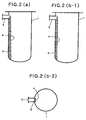
- Fig. 2 (a) shows one mode of a wall-wetting fall polymerization process, in which a prepolymer falls along and in contact with an inner wall of a cylindrical polymerizer.
- Fig. 2 (b-1) and Fig. 2 (b-2) the process of Fig. 2 (a) is illustrated on the assumption that the prepolymer of the same volume as in Fig. 2 (a), which falls along and in contact with the inner wall of the cylindrical polymerizer, is present in the form of a liquid mass having a uniform thickness and having a flowing liquid surface 4 having an arc configuration in cross-section, but not in the form of a wavy liquid mass as shown in Fig. 2 (a).
- the evaporation surface area S (m 2 ) is determined on the assumption that the evaporation surface is flowing liquid surface 4 having an arc configuration in cross-section as shown in Fig. 2 (b-1) and Fig. 2 (b-2).
- the areas of the side surfaces of the liquid mass shown in Fig. 2(b-2), which side surfaces extend along the thicknesswise direction of the liquid mass and are substantially perpendicular to flowing liquid surface 4, are not included in the evaporation surface area S (m 2 ), because each of these side surfaces does not have a configuration which is congruent with or homothetic to the polymer-flowing wall surface of the polymerizer. Further, as in Fig.
- the volume V (m 3 ) can be obtained by a method in which the weight of the polymer liquid in the polymerizer is obtained by subtracting the total weight of a polymer withdrawn from the polymerizer, an evaporated substance, such as a by-produced, evaporated aromatic monohydroxy compound, and a prepolymer in the conduits (arranged in the polymerizer) and the like from the weight of the prepolymer fed to the polymerizer; and the weight of the liquid in the polymerizer is then converted to the volume thereof, using the specific gravity (1,100 kg/cm 3 ) of the polymer liquid as measured at the polymerization temperature.
- the volume V (m 3 ) can be obtained by a method in which the weight of the polymer liquid in the polymerizer is obtained by subtracting the total weight of an evaporated substance, such as a by-produced, evaporated aromatic monohydroxy compound, and a prepolymer in the conduits and the like from the weight of the prepolymer fed to the polymerizer; and the weight of the polymer liquid in the polymerizer is then converted to the volume thereof, using the specific gravity (1,100 kg/m 3 ) of the polymer liquid as measured at the polymerization temperature.
- an evaporated substance such as a by-produced, evaporated aromatic monohydroxy compound, and a prepolymer in the conduits and the like
- Fig. 7 (a) is a diagrammatic horizontal cross-sectional view of a polymerizer, showing a polymerization process performed by allowing a polymer liquid to fall along and in contact with each of mutually adjacent two column-shaped guides, wherein the respective wavy flowing liquid surfaces on the two column-shaped guides 7A interfere with each other to thereby produce respective portions of both the wavy flowing liquid surfaces which portions are not exposed to the gas phase.
- Fig. 7 (b) the process of Fig. 7 (a) is illustrated on the assumption that the polymer liquid of the same volume as in Fig.
- the polymerization is performed under reaction conditions such that the evaporation surface area S (m 2 ), the volume V (m 3 ) of the liquid mass of polymerizable material in the polymerizer, and the number average molecular weight ( M n) of the aromatic polycarbonate to be produced satisfy the relationships represented by the following formula (1): log S / V ⁇ 2 ⁇ 10 - 5 ⁇ M ⁇ ⁇ n + 0.8 [It should be noted that formula (1) above is valid only when the unit of the evaporation surface area S is m 2 and the unit of the volume V of the liquid mass is m 3 .]
- the formula (1) is an empirical formula obtained by the present inventors in their production of polycarbonates having various average molecular weights under various polymerization conditions in which the S (m 2 )/V (m 3 ) ratio was varied.
- a polymerizer is used designed for performing a polymerization by allowing a polymer liquid to fall along and in contact with a surface of a guide. It is more preferred that the above-mentioned type of polymerizer have a plurality of guides. Examples of the shapes of the guide used in such a polymerizer include a plate, a cylinder, a cone, a chain and the like. Further, for example, the guide may be hollow.
- the polymerization may be performed by allowing a polymer liquid to fall along and in contact with an outer wall surface of the hollow guide, while introducing a heating medium to the hollow portion of the guide, or the polymerization may be performed by allowing a polymer liquid to fall along and in contact with an inner wall surface of the hollow guide, while applying a heating medium to the outer wall of the hollow guide.
- a single polymerizer which is constructed so as to achieve and maintain reaction conditions satisfying the formula (1) may be used, or a plurality of such polymerizers may be used.
- a polymerizer which is constructed so as to achieve and maintain reaction conditions satisfying the requirements of the present invention may be used in combination with other polymerizers for producing an aromatic polycarbonate.
- the method of the present invention is advantageous especially when the polymerizable material used has a relatively high viscosity (specifically, a polymerizable material having a number average molecular weight of about 1,500 or more).
- a prepolymer having a number average molecular weight not less than about 1,500 is produced by reacting an aromatic dihydroxy compound with a diaryl carbonate using, for example, a vertical agitation type polymerizer, and then the obtained prepolymer is polymerized using a polymerizer which is constructed so as to achieve and maintain reaction conditions satisfying the requirements of the present invention.
- Fig. 3 (a) and Fig. 3 (b) show polymerizer 1 having a plurality of plate-shaped guides 7, along and in contact with which polymer 3 is to be allowed to fall.
- Fig. 3 (a) is a diagrammatic vertical cross-sectional view of polymerizer 1, showing longitudinal cross-sections of the plate-shaped guides 7 taken in a thicknesswise direction thereof.
- Fig. 3 (b) is a diagrammatic cross-sectional view of the polymerizer of Fig. 3 (a), taken along the line III(b)-III(b).
- prepolymer 3 is fed through inlet 5 onto distributing plate 6 having holes, and is distributed by distributing plate 6 to the plurality of plate-shaped guides 7.
- Prepolymer 3 is allowed to fall along and in contact with both opposite flat surfaces of each plate-shaped guide 7.
- a by-produced aromatic monohydroxy compound and the like are evaporated from evaporation surface 4 of prepolymer 3.
- the interior of polymerizer 1 is maintained at reduced pressure.
- Polymer which has had its molecular weight increased during the guide-wetting fall thereof is discharged through outlet 10.
- the discharged polymer may be recirculated to inlet 5 and again allowed to fall along and in contact with plate-shaped guides 7 to further increase the molecular weight of the polymer.
- the polymerization may be performed in either a batchwise manner or a continuous manner. When the polymerization is performed in a batchwise manner, a polymer discharged from the polymerizer may be repeatedly recirculated to inlet 5.
- prepolymer 3 is continuously fed through inlet 5 and a polymer which has had its molecular weight increased during the guide-wetting fall thereof is continuously discharged through outlet 10.
- fresh prepolymer 3 is continuously fed through inlet 5, and a part of a discharged polymer which has had its molecular weight increased during the guide-wetting fall thereof is continuously recirculated to and fed through inlet 5 together with continuously fed fresh prepolymer 3, while continuously withdrawing the remainder of the discharged polymer from polymerizer 1 through outlet 10.
- the polymerizer is heated to and kept at an elevated temperature by means of a heater or a jacket (not shown).
- Guide 7 can be fixed, for example, to distributing plate 6 or to a wire hung from the upper inner wall of the polymerizer.
- this type polymerizer is commercially advantageous, since the production rate of an aromatic polycarbonate can be easily increased by increasing the surface area of plate-shaped guide 7 or increasing the number of plate-shaped guides 7, so that a scale-up of the production can be easily performed.
- Fig. 4 (a) and Fig. 4 (b) show polymerizer 1 having a plurality of column-shaped guides 7A, along and in contact with which polymer 3 is to be allowed to fall.
- Fig. 4 (a) is a diagrammatic vertical cross-sectional view of polymerizer 1.
- Fig. 4 (b) is a diagrammatic cross-sectional view of the polymerizer of Fig. 4 (a), taken along the line IV(b)-IV(b).
- prepolymer 3 is fed through inlet 5 onto distributing plate 6 having holes, and is distributed by distributing plate 6 to the plurality of column-shaped guides 7A. Prepolymer 3 is allowed to fall along and in contact with the surface of each column-shaped guide 7A.
- a by-produced aromatic monohydroxy compound and the like are evaporated from evaporation surface 4 of prepolymer 3.
- the interior of polymerizer 1 is maintained at reduced pressure.
- Polymer which has had its molecular weight increased during the guide-wetting fall thereof is discharged through outlet 10. It is requisite that the volume V (m 3 ) and the evaporation surface area S (m 2 ) of the liquid mass of the polymerizable material in the polymerizer, and the number average molecular weight M n of the polymer discharged from the polymerizer satisfy the relationship of the above-mentioned formula (1).
- the discharged polymer may be recirculated to inlet 5 and again allowed to fall along and in contact with column-shaped guides 7A to further increase the molecular weight of the polymer.
- the polymerization may be performed in either a batchwise manner or a continuous manner. When the polymerization is performed in a batchwise manner, a polymer discharged from the polymerizer may be repeatedly recirculated to inlet 5. When the polymerization is performed in a continuous manner, it is possible that prepolymer 3 is continuously fed through inlet 5 and a polymer which has had its molecular weight increased during the guide-wetting fall thereof is continuously discharged through outlet 10.
- fresh prepolymer 3 is continuously fed through inlet 5, and a part of a discharged polymer which has had its molecular weight increased during the guide-wetting fall thereof is continuously recirculated to and fed through inlet 5 together with continuously fed fresh prepolymer 3, while continuously withdrawing the remainder of the discharged polymer from polymerizer 1 through outlet 10.
- the polymerizer is heated to and kept at an elevated temperature by means of a heater or a jacket (not shown).
- Guide 7A can be fixed, for example, to distributing plate 6 or to a wire hung from the upper inner wall of the polymerizer.
- this type polymerizer is commercially advantageous, since the production rate of an aromatic polycarbonate can be easily increased by increasing the number of column-shaped guides 7A, so that a scale-up of the production can be easily performed.
- Fig. 5 shows polymerizer 1 having a plurality of cone-shaped guides 7B, along and in contact with which polymer 3 is to be allowed to fall.
- Fig. 5 is a diagrammatic vertical cross-sectional view of polymerizer 1.
- prepolymer 3 is fed through a pair of opposite inlets 5 and allowed to fall along and in contact with the uppermost first-stage cone-shaped guide.
- prepolymer 3, which has left the uppermost first-stage cone-shaped guide 7B reaches the second-stage cone-shaped guide 7B and is allowed to fall along and in contact with the second-stage cone-shaped guide.
- the prepolymer falls along and in contact with the vertically arranged several cone-shaped guides 7B successively until it reaches the bottom of the polymerizer.
- a by-produced aromatic monohydroxy compound and the like are evaporated from evaporation surface 4 of prepolymer 3.
- the interior of polymerizer 1 is maintained at reduced pressure.
- Polymer which has had its molecular weight increased during the guide-wetting fall thereof is discharged through outlet 10.
- the volume V (m 3 ) and the evaporation surface area S (m 2 ) of the liquid mass of the polymerizable material in the polymerizer, and the number average molecular weight M n of the polymer discharged from the polymerizer satisfy the relationship of the above-mentioned formula (1).
- the prepolymer has a portion which does not fall along and in contact with any guiding surface of a cone-shaped guide, but falls freely.
- the discharged polymer may be recirculated to inlets 5 and again allowed to fall along and in contact with cone-shaped guides 7B to further increase the molecular weight of the polymer.
- the polymerization may be performed in either a batchwise manner or a continuous manner. When the polymerization is performed in a batchwise manner, a polymer discharged from the polymerizer may be repeatedly recirculated to inlets 5.
- prepolymer 3 is continuously fed through a pair of opposite inlets 5 and a polymer which has had its molecular weight increased during the guide-wetting fall thereof is continuously discharged through outlet 10.
- fresh prepolymer 3 is continuously fed through inlets 5, and a part of a discharged polymer which has had its molecular weight increased during the guide-wetting fall thereof is continuously recirculated to and fed through inlets 5 together with continuously fed fresh prepolymer 3, while continuously withdrawing the remainder of the discharged polymer from polymerizer 1 through outlet 10.
- the polymerizer is heated to and kept at an elevated temperature by means of a heater or a jacket (not shown).
- each of umbrella-shaped guides disposed at intermediate portions in the polymerizer can be fixed, for example, to a rod projecting from an inner wall of the polymerizer or to a wire hung from the upper inner wall of the polymerizer.
- this type polymerizer is commercially advantageous, since the production rate of an aromatic polycarbonate can be easily increased by increasing the surface area of cone-shaped guide 7B, so that a scale-up of the production can be easily performed.
- Fig. 6 (a) and Fig. 6 (b) show polymerizer 1 having a plurality of cylindrical tubular guides 7C each having an inner wall surface, along and in contact with which polymer 3 is to be allowed to fall.
- Fig. 6 (a) is a diagrammatic vertical cross-sectional view of polymerizer 1.
- Fig. 6 (b) is a diagrammatic cross-sectional view of the polymerizer of Fig. 6 (a), taken along the line VI(b)-VI(b).
- prepolymer 3 is fed through inlet 5 to the polymerizer and accumulated at an upper portion of the interior of the polymerizer.
- the accumulated prepolymer 3 is distributed, by overflowing, to the plurality of cylindrical tubular guides 7C which are fixed to upper and lower portions of the inner walls of shell-chamber 11.
- Prepolymer 3 is allowed to fall along and in contact with the inner wall of each cylindrical tubular guide 7C.
- a by-produced aromatic monohydroxy compound and the like are evaporated from evaporation surface 4 of prepolymer 3.
- the interior of polymerizer 1 is maintained at reduced pressure. Not only an aromatic monohydroxy compound as a by-product and the like, but also an inert gas, which is optionally fed from gas feed port 8, is discharged through vent 9. Polymer which has had its molecular weight increased during the guide-wetting fall thereof is discharged through outlet 10.
- the discharged polymer may be recirculated to inlet 5 and again allowed to fall along and in contact with cylindrical tubular guides 7C to further increase the molecular weight of the polymer.
- the polymerization may be performed in either a batchwise manner or a continuous manner. When the polymerization is performed in a batchwise manner, a polymer discharged from the polymerizer may be repeatedly recirculated to inlet 5.
- prepolymer 3 is continuously fed through inlet 5 and a polymer which has had its molecular weight increased during the guide-wetting fall thereof is continuously discharged through outlet 10.
- fresh prepolymer 3 is continuously fed through inlet 5, and a part of a discharged polymer which has had its molecular weight increased during the guide-wetting fall thereof is continuously recirculated to and fed through inlet 5 together with continuously fed fresh prepolymer 3, while continuously withdrawing the remainder of the discharged polymer from polymerizer 1 through outlet 10.
- Shell-chamber 11 which is a space surrounding the outer wall surface of each cylindrical tubular guide 7C, is heated by a heating medium.
- the heating medium is fed to shell-chamber 11 through inlet 12 for heating medium and discharged through outlet 13.
- a heating medium conventional heating mediums can be used.
- heating mediums include various heating mediums described in pages 109 to 110 of "Netsu-kokanki Handbook (Handbook of Heat Exchangers)" (fifth edition, edited by the Editorial Committee of the Handbook of Heat Exchangers, and published by The Nikkan Kogyo Shimbun Ltd., Japan).
- Specific examples of heating mediums include heated steam, molten salt, SK-OIL#260, SK-OIL#240 and SK-OIL#170.
- this type polymerizer is commercially advantageous, since the production rate of an aromatic polycarbonate can be easily increased by increasing the number of cylindrical tubular guides 7C, so that a scale-up of the production can be easily performed.
- the volume V of the liquid mass of polymerizable material be 5 % or more, based on the internal volume of the polymerizer.
- the volume V of the liquid mass of polymerizable material is less than 5 %, based on the internal volume of the polymerizer, the size of the polymerizer needs to be large, which is commercially undesirable.
- the evaporation surface area S (m 2 ) of the liquid mass of polymerizable material satisfy the following formula (2): S ⁇ 0.03 Q wherein Q represents the rate (kg/hr) at which the aromatic polycarbonate is produced (hereinafter, frequently referred to simply as "production rate").
- formula (2) above is valid only when the unit of the evaporation surface area S is m 2 and the unit of the production rate Q is kg/hr.]
- the evaporation surface area S does not satisfy formula (2), it is possible that when the production of an aromatic polycarbonate is performed on a commercial scale, there arises a need of effecting an extremely efficient surface renewal of the polymer being formed, wherein the polymer is caused to sustain a large shear, leading to a lowering of the quality of the final polymer, for example, occurrence of discoloration.
- the method of the present invention is advantageous especially when the production of an aromatic polycarbonate is performed on a commercial scale.
- the production rate Q (kg/hr) of the aromatic polycarbonate There is no particular limitation with respect to the production rate Q (kg/hr) of the aromatic polycarbonate.
- the production rate Q (kg/hr) of the aromatic polycarbonate is produced be 1 kg/hr or more, more preferably 3 kg/hr or more.
- the polymerization temperature is generally in the range of from 100 to 350 °C, preferably from 150 to 290 °C.
- an aromatic monohydroxy compound is by-produced.
- the reaction rate can be increased. Therefore, in the method of the present invention, it is preferable to employ a method in which an inert gas which does not adversely affect the reaction, such as nitrogen, argon, helium, carbon dioxide and a lower hydrocarbon gas, is introduced so that the by-produced aromatic monohydroxy compound is entrained by the inert gas, and the inert gas entraining the aromatic monohydroxy compound is withdrawn to remove the aromatic monohydroxy compound, or a method in which the reaction is carried out under reduced pressure.
- an inert gas which does not adversely affect the reaction such as nitrogen, argon, helium, carbon dioxide and a lower hydrocarbon gas
- the preferred reaction pressure may vary depending on the type of the aromatic polycarbonate to be produced, the molecular weight of the molten monomer mixture or molten prepolymer, and the polymerization temperature.
- the reaction pressure is preferably from 6,660 Pa (50 mmHg) to atmospheric pressure.
- the reaction pressure is preferably from 400 to 6,660 Pa (3 to 50 mmHg).
- the reaction pressure is preferably 2,670 Pa (20 mmHg) or less, more preferably 1,330 Pa (10 mmHg) or less, still more preferably 267 Pa (2 mmHg) or less.
- the polymerization be carried out under reduced pressure while introducing an inert gas as mentioned above.
- the polymerization by the transesterification process may be carried out in the absence of a catalyst. However, when it is desired to accelerate the polymerization rate, the polymerization can be effected in the presence of a catalyst.
- the polymerization catalysts which are customarily used in the art can be used without particular limitations.
- Such catalysts include hydroxides of an alkali metal and of an alkaline earth metal, such as lithium hydroxide, sodium hydroxide, potassium hydroxide and calcium hydroxide; alkali metal salts, alkaline earth metal salts and quaternary ammonium salts of boron hydride and of aluminum hydride, such as lithium aluminum hydride, sodium boron hydride and tetramethyl ammonium boron hydride; hydrides of an alkali metal and of an alkaline earth metal, such as lithium hydride, sodium hydride and calcium hydride; alkoxides of an alkali metal and of an alkaline earth metal, such as lithium methoxide, sodium ethoxide and calcium methoxide; aryloxides of an alkali metal and of an alkaline earth metal, such as lithium phenoxide, sodium phenoxide, magnesium phenoxide, LiO-Ar-OLi wherein Ar represents an aryl group, and NaO-Ar-OL
- the catalysts can be used individually or in combination.
- the amount of the catalysts to be used is generally in the range of from 10 -8 to 1 % by weight, preferably from 10 -7 to 10 -1 % by weight, based on the weight of the aromatic dihydroxy compound.
- stainless steel, nickel or glass is generally used as a material for at least the inner wall portions of polymerizers.
- materials for the guide used in the present invention there is no particular limitation.
- preferred examples of materials for the guide include metals, glass and ceramics.
- metals include stainless steel, carbon steel, nickel, titanium, chromium and alloys, such as Hastelloy.
- the molecular weight is expressed in terms of the number average molecular weight (hereinafter referred to simply as " M n") as measured by gel permeation chromatography (GPC), utilizing the calibration curve obtained with respect to the standard polystyrene samples.
- M n number average molecular weight
- the color of the aromatic polycarbonate produced was evaluated, using a specimen having a thickness of 3.2 mm, in accordance with the CIELAB method, and the yellowness of the specimen is expressed in terms of the b*-value.
- Polymerizer 1 has an internal volume of 0.57 m 3 , and is equipped with five plate-shaped guides 7 made of stainless steel SUS316L, each having a thickness of 1 mm, a width of 0.1 m and a length of 7.5 m. Polymerizer 1 is also equipped with distributing plate 6, through which prepolymer 3 fed to polymerizer 1 can be distributed to plate-shaped guides 7 so that the distributed prepolymer 3 can be caused to uniformly fall along and in contact with the surfaces of both opposite sides of each of plate-shaped guides 7. Further, polymerizer 1 has an external jacket (not shown), and the inside of polymerizer 1 is heated by passing a heating medium through the jacket. Polymerizer 1 has no agitating means for the prepolymer.
- Each of the aromatic polycarbonate products obtained 25 hours and 50 hours after the start of the polymerization reaction had an M n of 11,200. Both of the aromatic polycarbonate products were colorless, transparent (b*-value: 3.4) and contained no impurities and thermal decomposition products.
- V w 1 - w 2 - w 3 / ⁇ - v 0
- w 1 was 1,250 kg
- w 2 was 1,064 kg
- w 3 was 10 kg
- v 0 was 0.01 m 3
- ⁇ was 1,100 kg/m 3 . Therefore, the liquid volume V of prepolymer 3 in polymerizer 1 at a point in time of 25 hours after the start of the reaction was determined as 0.15 m 3 . Also, from the evaporation surface area of the horizontal liquid surface of the liquid mass of prepolymer 3 at the bottom of polymerizer 1, the liquid volume of the prepolymer in the bottom portion of polymerizer 1 at a point in time of 25 hours after the start of the reaction was determined as 0.002 m 3 .
- the total amount of the prepolymer fed to polymerizer 1 during the polymerization reaction between the points in time of 25 hours and 50 hours after the start of the reaction was equal to the total amount of the aromatic polycarbonate product withdrawn from polymerizer 1 and the phenol and the like evaporated from polymerizer 1 during the polymerization reaction between the points in time of 25 hours and 50 hours after the start of the reaction. Also, the liquid volume V and the total evaporation surface area S determined 50 hours after the start of the reaction were equal to those determined 25 hours after the start of the reaction.
- the values of the left side and right side of the above-mentioned formula (1) were calculated and found to be 1.70 and 1.00, respectively.
- the liquid volume V of the prepolymer was 26 % of the internal volume of polymerizer 1.
- the rate Q at which the aromatic polycarbonate was produced was 49.6 kg/hr.
- the produced aromatic polycarbonate was molded at 300 °C to prepare a specimen having a thickness of 3.2 mm.
- the specimen was subjected to a heat aging test at 125 °C for 400 hours. As a result, it was found that the b*-value was 3.8, and the specimen did not suffer from marked discoloration.
- a polymerization reaction was conducted by continuously feeding a prepolymer, which had been prepared in the same manner as in Example 3, to an intermeshing-twin-screw evaporator (internal volume: 0.6 m 3 ; length: 3 m; total number of pitches of the screw: 1,000; and distance between two screws: 0.1 mm), while continuously withdrawing a produced polycarbonate from an outlet of the evaporator.
- the polymerization reaction was conducted under conditions such that the flow rate of the prepolymer, the reaction temperature and the reaction pressure were the same as those employed in Example 3, and the revolution rate of each screw was 30 rpm.
- each of the aromatic polycarbonate products obtained 25 hours and 50 hours after the start of the reaction had an M n of 5,100, which was only slightly higher than the M n of the prepolymer fed to the evaporator. Further, the aromatic polycarbonate products suffered from discoloration (b*-value: 3.9).
- each of the liquid volumes V's determined at points in time of 25 hours and 50 hours after the start of the reaction was 0.23 m 3
- each of the evaporation surface areas S's determined at points in time of 25 hours and 50 hours after the start of the reaction was 1.3 m 2 .
- a polymerization reaction was conducted by continuously feeding a prepolymer, which had been prepared in the same manner as in Example 3, to a horizontal agitation type reactor having twin-screw agitating blades (internal volume: 0.6 m 3 ; length: 3 m; rotation diameter of each agitating blade: 0.25 m), while continuously withdrawing a produced polycarbonate from an outlet of the reactor.
- the polymerization reaction was conducted under conditions such that the flow rate of the prepolymer, the reaction temperature and the reaction pressure were the same as those employed in Example 3, and the revolution rate of each screw was 15 rpm.
- each of the aromatic polycarbonate products obtained 25 hours and 50 hours after the start of the reaction had an M n of 5,100, which was only slightly higher than the M n of the prepolymer fed to the reactor. Further, the aromatic polycarbonate products suffered from discoloration (b*-value: 3.8).
- each of the liquid volumes V's determined at points in time of 25 hours and 50 hours after the start of the reaction was 0.24 m 3
- each of the evaporation surface areas S's determined at points in time of 25 hours and 50 hours after the start of the reaction was 1.4 m 2 .
- polymerizer 1 has a top chamber having inlet 5, shell chamber 11 and a bottom chamber having outlet 10, and is equipped with nine cylindrical tubular guides 7C made of stainless steel SUS316L, each of which tabular guides has an internal diameter of 53 mm and a length of 6 m.
- the top chamber communicates with the bottom chamber through the tabular guides.
- the top chamber and bottom chamber are adapted to be heated by passing a heating medium through shell chamber 11.
- the internal volume of polymerizer 1, i.e., the total of the volumes of the top chamber, shell chamber 11 and the bottom chamber, is 0.22 m 3 .
- Prepolymer 3 fed to the top chamber of polymerizer 1 through inlet 5 can be distributed to cylindrical tubular guides 7C by overflowing so that the distributed prepolymer 3 can be caused to uniformly fall along and in contact with the inner wall surface of cylindrical tubular guides 7C.
- Polymerizer 1 has no agitating means for the prepolymer.
- Each of the aromatic polycarbonate products obtained 25 hours and 50 hours after the start of the polymerization reaction had an M n of 10,100.
- Both of the aromatic polycarbonate products were colorless, transparent (b*-value: 3.4) and contained no impurities and thermal decomposition products.
- the liquid volume V (m 3 ) of prepolymer 3 contained in polymerizer 1 at a point in time of 25 hours after the start of the polymerization reaction was determined in substantially the same manner as in Example 1, and was found to be 0.13 m 3 . Also, from the horizontal liquid surface of the liquid mass of prepolymer 3 in the bottom portion of polymerizer 1, the liquid volume of the prepolymer in the bottom portion of polymerizer 1 at a point in time of 25 hours after the start of the reaction was determined as 0.018 m 3 . Therefore, the liquid volume of prepolymer 3 present in the cylindrical tubular guides 7C was determined as 0.112 m 3 .
- r 1 was 0.0265 m
- v 1 was 0.112 m 3
- n 1 was 9, and l 1 was 6 m.
- the evaporation surface area of the horizontal surface of the liquid mass of prepolymer 3 in the bottom portion of polymerizer 1 was 0.01 m 2 . From the above, it was found that the total evaporation surface area S of the prepolymer at a point in time of 25 hours after the start of the reaction was about 2.2 m 2 .
- the total amount of the prepolymer fed to polymerizer 1 during the polymerization reaction between the points in time of 25 hours and 50 hours after the start of the reaction was equal to the total amount of the aromatic polycarbonate product withdrawn from polymerizer 1 and the phenol and the like evaporated from polymerizer 1 during the polymerization reaction between the points in time of 25 hours and 50 hours after the start of the reaction. Also, the liquid volume V and the evaporation surface area S determined 50 hours after the start of the reaction were equal to those determined 25 hours after the start of the reaction.
- a polymerization reaction was carried out using substantially the same polymerizer as used in Example 6 [wherein a polymerizer as shown in Fig. 6(a) was used], except that outlet 10 and inlet 5 of the polymerizer are connected to each other by a circulation line so that a part of the produced polymer falling down to the bottom of the polymerizer 1 can be withdrawn from the outlet, while the remaining polymer can be returned to inlet 5 of polymerizer 1 through the circulation line.
- Polymerizer 1 has no agitating means for the prepolymer.
- the remaining polymer was returned to inlet 5 of polymerizer 1 at a flow rate of 200 kg/hr to thereby effect a further polymerization, so that the internal volume of the prepolymer in the bottom portion of polymerizer 1 was maintained at a constant level.
- Each of the aromatic polycarbonate products obtained 25 hours and 50 hours after the start of the polymerization reaction had an M n of 6,200. Both of the aromatic polycarbonate products were colorless, transparent (b*-value: 3.3) and contained no impurities and thermal decomposition products.
- the liquid volume V and the evaporation surface area S of prepolymer 3 contained in polymerizer 1 at a point in time of 25 hours and 50 hours after the start of the polymerization reaction were determined in the same manner as in Example 6.
- the liquid volume V and the total evaporation surface area S of prepolymer 3 contained in polymerizer 1 at a point in time of 25 hours after the start of the polymerization reaction were determined as 0.09 m 3 and 5.6 m 2 , respectively. Also, the liquid volume V and the total evaporation surface area S determined 50 hours after the start of the reaction were equal to those determined 25 hours after the start of the reaction.
- a polymerization reaction was carried out in substantially the same manner as in Example 7, except that the flow rate of prepolymer 3 to be returned to inlet 5 of polymerizer 1 through the circulation line was changed to 1,100 kg/hr, to thereby produce an aromatic polycarbonate.
- Each of the aromatic polycarbonate products obtained from outlet 10 at the points in time of 25 hours and 50 hours after the start of the polymerization reaction had an M n of 2,500.
- the increase in M n value during the polymerization that is, the difference in M n value between the produced aromatic polycarbonate and the fed prepolymer 3, was 700, which was not larger than 1/6 of the increase in M n value during the polymerization in Example 7.
- the liquid volume V of prepolymer 3 in polymerizer 1 and the total evaporation surface area S at each point in time of 25 hours and 50 hours from the start of the polymerization reaction were calculated in the same manner as in Example 6. As a result, it was found that each of the liquid volumes V was 0.13 m 3 and each of the evaporation surface areas S was 0.88 m 2 . Accordingly, the left side and right side of the above-mentioned formula (1) was 0.83 and 0.86, respectively. That is, the value of the left side was lower than that of the right side in formula (1).
- Polymerizer 1 has an internal volume of 0.6 m 3 and is equipped with thirty column-shaped guides 7A made of stainless steel SUS316L, each having a diameter of 1 mm and a length of 8 m. Polymerizer 1 is also equipped with distributing plate 6, through which prepolymer 3 fed to polymerizer 1 can be distributed to cylindrical guides 7A so that the distributed prepolymer 3 can be caused to uniformly fall along and in contact with the surface of each of cylindrical guides 7A. Further, the polymerizer 1 has an external jacket (not shown), and the inside of polymerizer 1 is adapted to be heated by passing a heating medium through the jacket. Polymerizer 1 has no agitating means for the prepolymer.
- Prepolymer 3 having an M n of 6,200 which had been prepared by reacting bisphenol A with diphenyl carbonate in a molar ratio of 1:1.05, was continuously fed to polymerizer 1 through inlet 5 at a flow rate of 18 kg/hr, so that a polymerization reaction of prepolymer 3 was carried out under polymerization reaction conditions wherein the reaction temperature was 265 °C, and the reaction pressure was 67 Pa (0.5 mmHg), while continuously withdrawing a produced aromatic polycarbonate from outlet 10.
- Each of the aromatic polycarbonate products obtained 25 hours and 50 hours after the start of the polymerization reaction had an M n of 11,700.
- Both of the aromatic polycarbonate products were colorless, transparent (b*-value: 3.4) and contained no impurities and thermal decomposition products.
- the liquid volume V of prepolymer 3 contained in polymerizer 1 at a point in time of 25 hours after the start of the polymerization reaction was determined as 0.07 m 3 in the same manner as in Example 1. Also, from the evaporation surface area of the horizontal liquid surface of the liquid mass of prepolymer 3 in the bottom portion of polymerizer 1, the liquid volume of the prepolymer in the bottom portion of polymerizer 1 at a point in time of 25 hours after the start of the reaction was determined as 0.015 m 3 . Accordingly, the volume of the liquid mass of the prepolymer 3 falling along and contact with the surface of each of cylindrical guides 7A was 0.055 m 3 .
- r 2 was 0.0005 m
- V 2 was 0.055 m 3
- n 2 was 30
- l 2 was 8 m.
- the evaporation surface area of the horizontal surface of the liquid mass of polymerizer 3 in the bottom of the polymerizer 1 determined 25 hours from the start of the reaction was 0.008 m 2 . From the above, it was found that the total evaporation surface area of the prepolymer at a point in time of 25 hours after the start of the reaction was 13.0 m 2 .
- the total amount of the prepolymer fed to polymerizer 1 during the polymerization reaction between the points in time of 25 hours and 50 hours after the start of the reaction was equal to the total amount of the aromatic polycarbonate product withdrawn from polymerizer 1 and of the phenol and the like evaporated from polymerizer 1 during the polymerization reaction between the points in time of 25 hours and 50 hours after the start of the reaction. Also, the liquid volume V and the evaporation surface area S determined 50 hours after the start of the reaction were equal to those determined 25 hours after the start of the reaction.
- the value of the left side and right side of the above-mentioned formula (1) were calculated and found to be 2.27 and 1.03, respectively.
- the liquid volume V of the prepolymer 3 was 12 % of the internal volume of polymerizer 1.
- the production rate Q of the produced aromatic polycarbonate was 17.8 kg/hr.
- the produced aromatic polycarbonate was molded into a specimen in the same manner as in Example 1. The specimen was subjected to a heat aging test. As a result, it was found that the b*-value was 3.9, and the specimen did not suffer from marked discoloration.
- a polymerization reaction was carried out in substantially the same manner as in Example 1, except that use was made of a prepolymer having an M n of 7,000, which had been prepared by reacting, in place of bisphenol A, 1,1-bis(4-hydroxyphenyl)-3,3,5-trimethylcyclohexane with diphenyl carbonate.
- Each of aromatic polycarbonate products withdrawn from outlet 10 after 25 hours and 50 hours from the start of the polymerization reaction had an M n of 11,000. Both of the aromatic polycarbonate products were colorless, transparent (b*-value: 3.4) and contained no impurities and thermal decomposition products.
- the liquid volume V of the prepolymer was 30 % of the internal volume of the polymerizer. Furthermore, the production rate of the produced aromatic polycarbonate was 49.7 kg/hr.
- Example 1 Substantially the same procedures as in Example 1 were individually repeated, except that use was made of prepolymers having M n of 7,000, which had been prepared by reacting, in place of bisphenol A, a mixture of bisphenol A and one compound selected from various types of aromatic dihydroxy compounds other than bisphenol A, with diphenyl carbonate.
- the molar ratio of bisphenol A to the aromatic dihydroxy compound was 1:1, and the total molar amount of the mixture of bisphenol A and the aromatic dihydroxy compound was equivalent to the molar amount of bisphenol A used in Example 1.
- the liquid volume V and total evaporation surface area S of the prepolymer were determined in the same manner as described in Example 1.
- Aromatic dihydroxy compound other than bisphenol A Aromatic polycarbonate product (after 50 hrs) Total evaporation surface area (S) (m 2 ) Liquid volume of prepolymer (V) (m 3 ) Formula (1) Liquid volume of prepolymer Production rate (O) of produced aromatic polycarbonate (kg/hr) M n b*-value left side right side internal volume of polymerizer (%)
- Example 14 10700 3.5 7.5 0.14 1.73 0.81 25 49.7
- Example 15 11700 3.4 7.5 0.15 1.70 1.03 26 49.6
- Example 16 11200 3.4 7.5 0.15 1.70 1.02 26 49.6
- Example 17 11800 3.4 7.5 0.15 1.70 1.03 26 49.6
- a polymerization reaction was carried out using a cylindrical polymerizer as shown in Fig. 4(a).
- the internal volume of polymerizer 1 is 0.28 m 3 .
- Polymerizer 1 is equipped with 50 column-shaped guides 7A made of stainless steel SUS316L, each having a diameter of 2 mm and a length of 4 m.
- Polymerizer 1 is also equipped with distributing plate 6, through which prepolymer 3 fed to the polymerizer 1 can be distributed to column-shaped guides 7A so that the distributed prepolymer 3 can be caused to uniformly fall along and in contact with the surface of the guides.
- Outlet 10 is connected to inlet 5 for prepolymer by a circulation line so that the prepolymer falling down to the bottom of polymerizer 1 can be returned to inlet 5 through the circulation line.
- Polymerizer 1 has no agitating means for the prepolymer.
- the liquid volume V of the prepolymer was calculated by subtracting the volume of the prepolymer, present in the circulation line and the like, and the volume of phenol and the like evaporated off from the polymerizer, from the volume of prepolymer 3 initially charged in the polymerizer, and was found to be 0.028 m 3 .
- the total evaporation surface area S was 1.8 m 2 .
- the left side and right side of the above-mentioned formula (1) were calculated and found to be 1.81 and 0.96, respectively.
- the liquid volume V of the prepolymer was 10 % of the internal volume of the polymerizer.
- the production rate Q of the produced aromatic polycarbonate was 16.3 kg/hr.
- the method of the present invention not only can a high quality aromatic polycarbonate having high heat resistance be obtained at high polymerization rate without suffering problems (such as discoloration, entry of impurities and generation of a thermal decomposition product) which are likely to be encountered in the production by a conventional method, but also a very large motive power for agitation is not needed and a scale-up of the polycarbonate production is easy. Therefore, the method of the present invention is commercially advantageous.
Landscapes
- Chemical & Material Sciences (AREA)
- Health & Medical Sciences (AREA)
- Chemical Kinetics & Catalysis (AREA)
- Medicinal Chemistry (AREA)
- Polymers & Plastics (AREA)
- Organic Chemistry (AREA)
- Polyesters Or Polycarbonates (AREA)
Claims (4)
- Verfahren zur Herstellung eines aromatischen Polycarbonats, umfassend die Anwendung einer Umesterungsreaktion in einer Polymerisationsvorrichtung auf wenigstens ein polymerisierbares Material, ausgewählt aus der Gruppe bestehend aus:einer geschmolzenen Monomermischung aus einer aromatischen Dihydroxyverbindung und einem Diarylcarbonat undeinem geschmolzenen Prepolymer, erhalten durch ein Verfahren, das die Umsetzung einer aromatischen Dihydroxyverbindung mit einem Diarylcarbonat umfasst,wobei das polymerisierbare Material in Form einer flüssigen Masse in der Polymerisationsvorrichtung vorhanden ist und wobei die in der Polymerisationsvorrichtung umgeesterte flüssige Masse aus polymerisierbarem Material eine freiliegende Oberfläche aufweist,
wobei die Umesterungsreaktion der flüssigen Masse aus polymerisierbarem Material in einem Benetzungs-Fallmodus so durchgeführt wird, dass das Fallen der flüssigen Masse aus einem polymerisierbaren Material entlang und in Kontakt mit einer Fläche einer in der Polymerisationsvorrichtung ausgebildeten Führung bewirkt wird,
wobei die Verbesserung darin besteht, dass die Umesterungsreaktion der flüssigen Masse aus polymerisierbarem Material unter Reaktionsbedingungen so durchgeführt wird, dass die folgende Formel (1) erfüllt wird:
wobei:S eine Verdampfungsfläche (m2) darstellt, die als die Fläche (m2) der freiliegenden Fläche der flüssigen Masse aus polymerisierbarem Material definiert ist;V das Volumen (m3) der flüssigen Masse des polymerisierbaren Materials in der Polymerisationsvorrichtung darstellt undM n das Zahlenmittel der Molmasse des herzustellenden aromatischen Polycarbonats darstellt. - Verfahren nach Anspruch 1, wobei das Volumen V (m3) der flüssigen Masse aus polymerisierbarem Material 5 % oder mehr, bezogen auf das Innenvolumen der Polymerisationsvorrichtung, beträgt.
- Verfahren nach einem der Ansprüche 1 oder 2, wobei die Verdampfungsfläche S (m2) der flüssigen Masse aus polymerisierbarem Material die folgende Formel (2) erfüllt:

wobei Q die Rate (kg/h) darstellt, mit der das aromatische Polycarbonat erzeugt wird. - Verfahren nach Anspruch 3, wobei die Rate Q (kg/h), mit der das aromatische Polycarbonat erzeugt wird, 1 kg/h oder mehr beträgt.
Applications Claiming Priority (4)
| Application Number | Priority Date | Filing Date | Title |
|---|---|---|---|
| JP32736995 | 1995-12-15 | ||
| JP32736995 | 1995-12-15 | ||
| JP327369/95 | 1995-12-15 | ||
| PCT/JP1996/003658 WO1997022650A1 (fr) | 1995-12-15 | 1996-12-13 | Procede de preparation de polycarbonate aromatique |
Publications (4)
| Publication Number | Publication Date |
|---|---|
| EP0867459A1 EP0867459A1 (de) | 1998-09-30 |
| EP0867459A4 EP0867459A4 (de) | 2000-10-11 |
| EP0867459B1 EP0867459B1 (de) | 2004-03-10 |
| EP0867459B2 true EP0867459B2 (de) | 2007-10-24 |
Family
ID=18198377
Family Applications (1)
| Application Number | Title | Priority Date | Filing Date |
|---|---|---|---|
| EP96941875A Expired - Lifetime EP0867459B2 (de) | 1995-12-15 | 1996-12-13 | Verfahren zur herstellung von aromatischem polycarbonat |
Country Status (12)
| Country | Link |
|---|---|
| US (1) | US5840826A (de) |
| EP (1) | EP0867459B2 (de) |
| JP (1) | JP3202993B2 (de) |
| KR (1) | KR100257913B1 (de) |
| CN (1) | CN1078219C (de) |
| AT (1) | ATE261465T1 (de) |
| CA (1) | CA2232427C (de) |
| DE (1) | DE69631836T3 (de) |
| ES (1) | ES2213785T5 (de) |
| MY (1) | MY113933A (de) |
| TW (1) | TW412549B (de) |
| WO (1) | WO1997022650A1 (de) |
Families Citing this family (12)
| Publication number | Priority date | Publication date | Assignee | Title |
|---|---|---|---|---|
| WO2001060718A2 (en) * | 2000-02-17 | 2001-08-23 | Bintech. Lllp | Bulk materials management apparatus and method |
| JP4267363B2 (ja) | 2003-05-07 | 2009-05-27 | 旭化成ケミカルズ株式会社 | 光学情報基板用ポリカーボネート組成物 |
| USPP16118P3 (en) * | 2004-04-22 | 2005-11-15 | Florfis Ag | New Guinea Impatiens plant named ‘Fisupnic Lipink’ |
| JP4181600B2 (ja) * | 2004-06-14 | 2008-11-19 | 旭化成ケミカルズ株式会社 | 芳香族ポリカーボネートの改良された製造方法 |
| KR100813451B1 (ko) * | 2004-06-14 | 2008-03-13 | 아사히 가세이 케미칼즈 가부시키가이샤 | 방향족 폴리카르보네이트를 효율적으로 제조하는 방법 |
| EA008890B1 (ru) * | 2004-06-16 | 2007-08-31 | Асахи Касеи Кемикалз Корпорейшн | Полимеризационное устройство для получения ароматических поликарбонатов |
| WO2006041075A1 (ja) | 2004-10-14 | 2006-04-20 | Asahi Kasei Chemicals Corporation | 高純度ジアリールカーボネートの製造方法 |
| WO2007063757A1 (ja) * | 2005-11-30 | 2007-06-07 | Asahi Kasei Chemicals Corporation | 高品質芳香族ポリカーボネートの工業的製造方法 |
| TW200738781A (en) * | 2005-12-12 | 2007-10-16 | Asahi Kasei Chemicals Corp | Process for industrially producing high-quality aromatic polycarbonate |
| CN101875720A (zh) * | 2010-07-02 | 2010-11-03 | 天津大学 | 制备高分子量缩聚物的方法与设备 |
| CN103180360B (zh) | 2010-10-29 | 2015-04-29 | 旭化成化学株式会社 | 缩聚反应性聚合物的制造方法和聚合器 |
| JP2017105996A (ja) * | 2015-12-08 | 2017-06-15 | 本州化学工業株式会社 | 芳香族ポリカーボネートオリゴマー |
Citations (1)
| Publication number | Priority date | Publication date | Assignee | Title |
|---|---|---|---|---|
| DE1495730A1 (de) † | 1963-07-24 | 1969-04-10 | Bayer Ag | Verfahren zur Herstellung thermoplastischer Polykondensationsprodukte |
Family Cites Families (14)
| Publication number | Priority date | Publication date | Assignee | Title |
|---|---|---|---|---|
| US3888826A (en) * | 1972-07-10 | 1975-06-10 | Mitsubishi Gas Chemical Co | Process for preparing aromatic polycarbonates |
| JPS5210266B2 (de) * | 1972-08-02 | 1977-03-23 | ||
| JPS5236159B2 (de) * | 1972-12-13 | 1977-09-13 | ||
| JPS5019600A (de) * | 1973-06-12 | 1975-03-01 | ||
| JPS535719A (en) * | 1976-07-05 | 1978-01-19 | Hitachi Ltd | Dc-dc convertor |
| JP2674813B2 (ja) * | 1988-12-06 | 1997-11-12 | 日本ジーイープラスチックス 株式会社 | ポリカーボネートの製造方法 |
| JPH085957B2 (ja) * | 1990-07-12 | 1996-01-24 | 出光石油化学株式会社 | ポリカーボネートの製造方法 |
| JPH04106124A (ja) * | 1990-08-24 | 1992-04-08 | Daicel Chem Ind Ltd | ポリカーボネートの製造法 |
| ATE208799T1 (de) * | 1993-07-23 | 2001-11-15 | Asahi Chemical Ind | Verfahren zur herstellung von aromatischem polycarbonat |
| JP3367245B2 (ja) * | 1995-01-18 | 2003-01-14 | 三菱化学株式会社 | ビス(β−ヒドロキシエチル)テレフタレート類の製造法 |
| US5476919A (en) * | 1995-02-21 | 1995-12-19 | Minnesota Mining And Manufacturing Company | Process for esterification |
| JP3379265B2 (ja) * | 1995-03-02 | 2003-02-24 | 三菱化学株式会社 | 芳香族ポリカーボネート樹脂の製造方法 |
| JPH106124A (ja) * | 1996-06-18 | 1998-01-13 | Mitsubishi Plastics Ind Ltd | プラスチック積層金属板の剪断加工方法 |
| JP4072327B2 (ja) * | 2001-10-15 | 2008-04-09 | キヤノン株式会社 | プロファイルの調整装置およびその方法 |
-
1996
- 1996-12-13 EP EP96941875A patent/EP0867459B2/de not_active Expired - Lifetime
- 1996-12-13 ES ES96941875T patent/ES2213785T5/es not_active Expired - Lifetime
- 1996-12-13 CA CA002232427A patent/CA2232427C/en not_active Expired - Lifetime
- 1996-12-13 DE DE69631836T patent/DE69631836T3/de not_active Expired - Lifetime
- 1996-12-13 JP JP52265797A patent/JP3202993B2/ja not_active Expired - Lifetime
- 1996-12-13 WO PCT/JP1996/003658 patent/WO1997022650A1/ja not_active Ceased
- 1996-12-13 AT AT96941875T patent/ATE261465T1/de not_active IP Right Cessation
- 1996-12-13 CN CN96197638A patent/CN1078219C/zh not_active Expired - Lifetime
- 1996-12-13 US US08/913,781 patent/US5840826A/en not_active Expired - Lifetime
- 1996-12-14 TW TW085115472A patent/TW412549B/zh not_active IP Right Cessation
- 1996-12-16 MY MYPI96005291A patent/MY113933A/en unknown
-
1998
- 1998-04-14 KR KR1019980702729A patent/KR100257913B1/ko not_active Expired - Lifetime
Patent Citations (1)
| Publication number | Priority date | Publication date | Assignee | Title |
|---|---|---|---|---|
| DE1495730A1 (de) † | 1963-07-24 | 1969-04-10 | Bayer Ag | Verfahren zur Herstellung thermoplastischer Polykondensationsprodukte |
Non-Patent Citations (5)
| Title |
|---|
| Abbas, Kent B.,"Thermal degradation of bisphenol A polycarbonate", POLYMER, 1980, Vol.21, August, pp.936-940 † |
| Dobkowski, Z., "Influence of Polydispersity and long chain branching on the melt viscosity of polycarbonate", Eur. Polym. J.,1982, Vol.18, pp. 1051-1059 † |
| Encyclopedia of Chemical Processing and Design 40; 1992, pp. 137-138 † |
| Encyclopedia of Polymer Science and Engineering, Vol. 11, 1988, pp.651-652 † |
| Van Krevelen, D.W., "Properties of Polymer", 1997, p.22 † |
Also Published As
| Publication number | Publication date |
|---|---|
| ATE261465T1 (de) | 2004-03-15 |
| CN1200131A (zh) | 1998-11-25 |
| ES2213785T3 (es) | 2004-09-01 |
| ES2213785T5 (es) | 2008-03-01 |
| CN1078219C (zh) | 2002-01-23 |
| EP0867459A4 (de) | 2000-10-11 |
| DE69631836T3 (de) | 2008-06-12 |
| MY113933A (en) | 2002-06-29 |
| US5840826A (en) | 1998-11-24 |
| CA2232427A1 (en) | 1997-06-26 |
| EP0867459B1 (de) | 2004-03-10 |
| TW412549B (en) | 2000-11-21 |
| KR100257913B1 (en) | 2000-06-01 |
| EP0867459A1 (de) | 1998-09-30 |
| WO1997022650A1 (fr) | 1997-06-26 |
| DE69631836T2 (de) | 2005-01-05 |
| DE69631836D1 (de) | 2004-04-15 |
| JP3202993B2 (ja) | 2001-08-27 |
| CA2232427C (en) | 2001-06-19 |
Similar Documents
| Publication | Publication Date | Title |
|---|---|---|
| US5589564A (en) | Wire-wetting fall polymonization process for the production of polycarbonates | |
| EP1048685B1 (de) | Verfahren und polymerisationsvorrichtung zur herstellung von aromatischem polycarbonat | |
| USRE38050E1 (en) | Polycarbonate comprising different kinds of bonding units and process for the preparation thereof | |
| EP0867459B2 (de) | Verfahren zur herstellung von aromatischem polycarbonat | |
| US5596067A (en) | Free fall polymerization process for the production of polycarbonates | |
| US6320015B1 (en) | Process for producing aromatic polycarbonate | |
| EP1760107B1 (de) | Verfahren zur effizienten herstellung von aromatischem polycarbonat | |
| JPWO1999064492A1 (ja) | 芳香族ポリカーボネートの製造方法 | |
| JPWO1997022650A1 (ja) | 芳香族ポリカーボネートの製造方法 | |
| EP1760109B1 (de) | Verbessertes verfahren zur herstellung von aromatischem polycarbonat | |
| EP1760108B1 (de) | Polymerisationsgerät zur herstellung von aromatischem polycarbonat | |
| JP3966553B2 (ja) | 芳香族ポリカーボネートを製造するためのシステム | |
| EP0927746B1 (de) | Zusammensetzung eines aromatischen polycarbonates | |
| JP3199644B2 (ja) | 芳香族ポリカーボネートの製造方法 | |
| US6037437A (en) | Method for producing an aromatic polycarbonate | |
| US5952449A (en) | Method for producing an aromatic polycarbonate |
Legal Events
| Date | Code | Title | Description |
|---|---|---|---|
| PUAI | Public reference made under article 153(3) epc to a published international application that has entered the european phase |
Free format text: ORIGINAL CODE: 0009012 |
|
| 17P | Request for examination filed |
Effective date: 19980305 |
|
| AK | Designated contracting states |
Kind code of ref document: A1 Designated state(s): AT BE CH DE ES FR GB IT LI LU NL SE |
|
| RBV | Designated contracting states (corrected) |
Designated state(s): AT BE CH DE ES FR GB IT LI LU NL SE |
|
| A4 | Supplementary search report drawn up and despatched |
Effective date: 20000830 |
|
| AK | Designated contracting states |
Kind code of ref document: A4 Designated state(s): AT BE CH DE ES FR GB IT LI LU NL SE |
|
| RAP1 | Party data changed (applicant data changed or rights of an application transferred) |
Owner name: ASAHI KASEI KABUSHIKI KAISHA |
|
| REG | Reference to a national code |
Ref country code: GB Ref legal event code: FG4D |
|
| GRAP | Despatch of communication of intention to grant a patent |
Free format text: ORIGINAL CODE: EPIDOSNIGR1 |
|
| GRAS | Grant fee paid |
Free format text: ORIGINAL CODE: EPIDOSNIGR3 |
|
| GRAA | (expected) grant |
Free format text: ORIGINAL CODE: 0009210 |
|
| AK | Designated contracting states |
Kind code of ref document: B1 Designated state(s): AT BE CH DE ES FR GB IT LI LU NL SE |
|
| PG25 | Lapsed in a contracting state [announced via postgrant information from national office to epo] |
Ref country code: LI Free format text: LAPSE BECAUSE OF FAILURE TO SUBMIT A TRANSLATION OF THE DESCRIPTION OR TO PAY THE FEE WITHIN THE PRESCRIBED TIME-LIMIT Effective date: 20040310 Ref country code: IT Free format text: LAPSE BECAUSE OF FAILURE TO SUBMIT A TRANSLATION OF THE DESCRIPTION OR TO PAY THE FEE WITHIN THE PRE;WARNING: LAPSES OF ITALIAN PATENTS WITH EFFECTIVE DATE BEFORE 2007 MAY HAVE OCCURRED AT ANY TIME BEFORE 2007. THE CORRECT EFFECTIVE DATE MAY BE DIFFERENT FROM THE ONE RECORDED.SCRIBED TIME-LIMIT Effective date: 20040310 Ref country code: FR Free format text: LAPSE BECAUSE OF FAILURE TO SUBMIT A TRANSLATION OF THE DESCRIPTION OR TO PAY THE FEE WITHIN THE PRESCRIBED TIME-LIMIT Effective date: 20040310 Ref country code: CH Free format text: LAPSE BECAUSE OF FAILURE TO SUBMIT A TRANSLATION OF THE DESCRIPTION OR TO PAY THE FEE WITHIN THE PRESCRIBED TIME-LIMIT Effective date: 20040310 Ref country code: AT Free format text: LAPSE BECAUSE OF FAILURE TO SUBMIT A TRANSLATION OF THE DESCRIPTION OR TO PAY THE FEE WITHIN THE PRESCRIBED TIME-LIMIT Effective date: 20040310 |
|
| REG | Reference to a national code |
Ref country code: CH Ref legal event code: EP |
|
| REF | Corresponds to: |
Ref document number: 69631836 Country of ref document: DE Date of ref document: 20040415 Kind code of ref document: P |
|
| PG25 | Lapsed in a contracting state [announced via postgrant information from national office to epo] |
Ref country code: SE Free format text: LAPSE BECAUSE OF FAILURE TO SUBMIT A TRANSLATION OF THE DESCRIPTION OR TO PAY THE FEE WITHIN THE PRESCRIBED TIME-LIMIT Effective date: 20040610 |
|
| REG | Reference to a national code |
Ref country code: ES Ref legal event code: FG2A Ref document number: 2213785 Country of ref document: ES Kind code of ref document: T3 |
|
| REG | Reference to a national code |
Ref country code: CH Ref legal event code: PL |
|
| PLBI | Opposition filed |
Free format text: ORIGINAL CODE: 0009260 |
|
| PG25 | Lapsed in a contracting state [announced via postgrant information from national office to epo] |
Ref country code: LU Free format text: LAPSE BECAUSE OF NON-PAYMENT OF DUE FEES Effective date: 20041213 Ref country code: GB Free format text: LAPSE BECAUSE OF NON-PAYMENT OF DUE FEES Effective date: 20041213 |
|
| PLAX | Notice of opposition and request to file observation + time limit sent |
Free format text: ORIGINAL CODE: EPIDOSNOBS2 |
|
| 26 | Opposition filed |
Opponent name: BAYER MATERIALSCIENCE AG Effective date: 20041207 |
|
| NLS | Nl: assignments of ep-patents |
Owner name: ASAHI KASEI CHEMICALS CORPORATION |
|
| EN | Fr: translation not filed | ||
| NLR1 | Nl: opposition has been filed with the epo |
Opponent name: BAYER MATERIALSCIENCE AG |
|
| PLAX | Notice of opposition and request to file observation + time limit sent |
Free format text: ORIGINAL CODE: EPIDOSNOBS2 |
|
| PLAF | Information modified related to communication of a notice of opposition and request to file observations + time limit |
Free format text: ORIGINAL CODE: EPIDOSCOBS2 |
|
| GBPC | Gb: european patent ceased through non-payment of renewal fee |
Effective date: 20041213 |
|
| PLBB | Reply of patent proprietor to notice(s) of opposition received |
Free format text: ORIGINAL CODE: EPIDOSNOBS3 |
|
| PUAH | Patent maintained in amended form |
Free format text: ORIGINAL CODE: 0009272 |
|
| STAA | Information on the status of an ep patent application or granted ep patent |
Free format text: STATUS: PATENT MAINTAINED AS AMENDED |
|
| 27A | Patent maintained in amended form |
Effective date: 20071024 |
|
| AK | Designated contracting states |
Kind code of ref document: B2 Designated state(s): AT BE CH DE ES FR GB IT LI LU NL SE |
|
| NLR2 | Nl: decision of opposition |
Effective date: 20071024 |
|
| REG | Reference to a national code |
Ref country code: ES Ref legal event code: DC2A Date of ref document: 20071025 Kind code of ref document: T5 |
|
| NLR3 | Nl: receipt of modified translations in the netherlands language after an opposition procedure | ||
| EN | Fr: translation not filed | ||
| PGFP | Annual fee paid to national office [announced via postgrant information from national office to epo] |
Ref country code: DE Payment date: 20151208 Year of fee payment: 20 |
|
| PGFP | Annual fee paid to national office [announced via postgrant information from national office to epo] |
Ref country code: BE Payment date: 20151207 Year of fee payment: 20 Ref country code: NL Payment date: 20151110 Year of fee payment: 20 Ref country code: ES Payment date: 20151112 Year of fee payment: 20 |
|
| REG | Reference to a national code |
Ref country code: DE Ref legal event code: R082 Ref document number: 69631836 Country of ref document: DE Representative=s name: DOMPATENT VON KREISLER SELTING WERNER - PARTNE, DE Ref country code: DE Ref legal event code: R081 Ref document number: 69631836 Country of ref document: DE Owner name: ASAHI KASEI KABUSHIKI KAISHA, JP Free format text: FORMER OWNER: ASAHI KASEI CHEMICALS CORPORATION, TOKIO/TOKYO, JP |
|
| REG | Reference to a national code |
Ref country code: NL Ref legal event code: PD Owner name: ASAHI KASEI KABUSHIKI KAISHA; JP Free format text: DETAILS ASSIGNMENT: VERANDERING VAN EIGENAAR(S), SAMENVOEGEN; FORMER OWNER NAME: ASAHI KASEI CHEMICALS CORPORATION Effective date: 20160722 |
|
| REG | Reference to a national code |
Ref country code: ES Ref legal event code: PC2A Owner name: ASAHI KASEI KABUSHIKI KAISHA Effective date: 20160923 |
|
| REG | Reference to a national code |
Ref country code: DE Ref legal event code: R071 Ref document number: 69631836 Country of ref document: DE |
|
| REG | Reference to a national code |
Ref country code: NL Ref legal event code: MK Effective date: 20161212 |
|
| PG25 | Lapsed in a contracting state [announced via postgrant information from national office to epo] |
Ref country code: ES Free format text: LAPSE BECAUSE OF EXPIRATION OF PROTECTION Effective date: 20161214 |