EP0864820A2 - Méthode pour régler un sytème de circulation d'air - Google Patents
Méthode pour régler un sytème de circulation d'air Download PDFInfo
- Publication number
- EP0864820A2 EP0864820A2 EP98103663A EP98103663A EP0864820A2 EP 0864820 A2 EP0864820 A2 EP 0864820A2 EP 98103663 A EP98103663 A EP 98103663A EP 98103663 A EP98103663 A EP 98103663A EP 0864820 A2 EP0864820 A2 EP 0864820A2
- Authority
- EP
- European Patent Office
- Prior art keywords
- air
- outlet
- outlet device
- width
- opening
- Prior art date
- Legal status (The legal status is an assumption and is not a legal conclusion. Google has not performed a legal analysis and makes no representation as to the accuracy of the status listed.)
- Granted
Links
Images

Classifications
-
- F—MECHANICAL ENGINEERING; LIGHTING; HEATING; WEAPONS; BLASTING
- F24—HEATING; RANGES; VENTILATING
- F24F—AIR-CONDITIONING; AIR-HUMIDIFICATION; VENTILATION; USE OF AIR CURRENTS FOR SCREENING
- F24F13/00—Details common to, or for air-conditioning, air-humidification, ventilation or use of air currents for screening
- F24F13/02—Ducting arrangements
- F24F13/06—Outlets for directing or distributing air into rooms or spaces, e.g. ceiling air diffuser
- F24F13/075—Outlets for directing or distributing air into rooms or spaces, e.g. ceiling air diffuser having parallel rods or lamellae directing the outflow, e.g. the rods or lamellae being individually adjustable
-
- F—MECHANICAL ENGINEERING; LIGHTING; HEATING; WEAPONS; BLASTING
- F24—HEATING; RANGES; VENTILATING
- F24F—AIR-CONDITIONING; AIR-HUMIDIFICATION; VENTILATION; USE OF AIR CURRENTS FOR SCREENING
- F24F11/00—Control or safety arrangements
- F24F11/70—Control systems characterised by their outputs; Constructional details thereof
- F24F11/72—Control systems characterised by their outputs; Constructional details thereof for controlling the supply of treated air, e.g. its pressure
- F24F11/74—Control systems characterised by their outputs; Constructional details thereof for controlling the supply of treated air, e.g. its pressure for controlling air flow rate or air velocity
-
- F—MECHANICAL ENGINEERING; LIGHTING; HEATING; WEAPONS; BLASTING
- F24—HEATING; RANGES; VENTILATING
- F24F—AIR-CONDITIONING; AIR-HUMIDIFICATION; VENTILATION; USE OF AIR CURRENTS FOR SCREENING
- F24F7/00—Ventilation
- F24F7/04—Ventilation with ducting systems, e.g. by double walls; with natural circulation
Definitions
- the present invention relates to a method for adjustment of an air duct system and in particular that of Exhaust devices of an air duct system flowing out Air volume, as well as a corresponding air duct system.
- Air guidance systems are in a variety of forms and designs known and on the market. There is a very big one Number of ventilation grilles and outlets with the most varied Quantity settings. The quantity setting is mostly based on the individual ventilation grille, i.e., it is determined with appropriate measuring elements the amount of air flowing out. Should this be changed the change will also be made to each individual ventilation grille performed. This has major drawbacks since each grid is measured after installation got to.
- From DE-GM 18 65 251 is an air steering blind for loading / or Ventilation of rooms shown in which A swiveling cover can be moved to the rear of the air steering blind is assigned to a certain amount of air discharge regulate.
- the present invention is based on the object Procedure of the above Way to develop with which from a Plurality of air flowing out of exhaust devices is evened out in a simple manner.
- one in the airflow first outlet device is set so that a predetermined amount of air from the exhaust device flows out, after which the setting on the subsequent outlet devices is transferred.
- an outlet device the amount of air flowing out desired value is set, on the one hand the Width of the opening of this outlet device and the other the amount of air supplied by regulating the fan be coordinated.
- the outlet device provided measuring elements that determine the differential pressure in the air flow. After that is done also change the width of the opening until the desired one Value of outflowing air volume is reached.
- the present invention relates primarily to the outlet devices with slit shutters, as they come from the EP 0 386 717 are known. Through this slider the amount of air can be regulated easily and very precisely. On the one hand, it is possible to close the slider by hand adjust by engaging the exhaust device from the front and the slider on the slats back and forth is moved. However, any other is also conceivable possible adjustment on mechanical, electromotive, pneumatic or hydraulic way. E.g. it is conceivable that a tongue protrudes from the slit slide and protrudes from the air duct system and there as a display serves for a scale. A setting of the slider of successive outlet devices then takes place using the same scale values.
- Such a method according to the invention is above all applicable to an air duct system in which the exhaust devices are arranged one after the other. It does not matter what type of outlet device it concerns and whether the air duct system one has a round or angular cross-section. It turned out that when exposed to a wide variety of Pressing 10, 20 or 30 Pa, for example, the air volume changed that emerges from the outlet devices, however, the even amount of discharge does not change. This is an extraordinary advantage of the present one Invention.
- an air duct system consists of a plurality of air outlets R 1 - R 6 , each with outlet devices 6.1 - 6.6.
- the air outlets R 1 - R 6 can have different diameters and can be round or angular in cross section. Intermediate pieces (not shown) can also be arranged between the individual air outlets R 1 - R 6 without outlet devices.
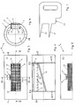
- an air outlet R has a tube 1, which has openings 2, 3 on the end face.
- this tube 1 in particular in its outer surface 4, an outlet opening 5 is provided. This is elongated and preferably in the longitudinal direction of the tube 1 from the outer surface 4 punched out.
- An outlet device is located behind this outlet opening 5 6 used.
- the outlet device 6 through the Openings 2 or 3 are pushed into tube 1 or be used through the outlet opening 5.
- the outlet device is located 6 over an arcuate edge strip 7 one Inner surface 8 of the tube 4.
- This edge strip 7 is in curved with a radius of the inner surface 8 of the tube 1, as shown in Figure 4.
- the outlet device 6 can be of a conventional type, for example. provided as a grille with lamellae 9 to keep an air flow in to direct appropriate directions.
- the slats 9 are arranged in the longitudinal direction and completely engage behind the outlet opening 5.
- the slats 9 of the outlet device 6 is a slit slide 10 to limit and / or regulate the resigned Volume flow upstream.
- Such a slider is known, for example, from EP 0 386 717 A1, to which explicit reference is made.
- Rings 11 are provided so that the outlet device 6 is fixed inside the tube 1 and is centered there.
- the outlet device 6 is inserted into the tube 1 and the rings 11.1, 11.2 are pushed through the openings 2, 3 from both sides. These press on the edge strips 7.1 and 7.2.
- clamping elements screws or similar fastening elements (not shown here) can additionally be used to secure the rings 11.1 and 11.2 and thus the outlet device 6 against twisting and slipping in the tube 1.
- fastening elements for example rivets.
- FIG. 3 it is indicated that, instead of the slats 9 or in addition to the slats 9, the outlet opening 5 can be covered by a perforated plate 12.
- FIG. 5 shows a further exemplary embodiment of an air outlet R a , in which a multiplicity of slots 13 are punched into a jacket 4.1.
- the slot slider 10 is by clip strips 16.1 and 16.2 held as indicated in Figure 4 and in the EP 0 386 717 A1 are described in more detail. These brackets 16 let the slider 10 move in the direction of the double arrow x, this shifting is easy can be done by hand when through the slats 9th is reached through.
- the amount of displacement can be based on a Scale 18 can be read.
- the outlet device 6.1 of the first air outlet R 1 is also assigned a scoop tongue 19, which projects obliquely from the rear wall 15 of the outlet device 6 into the air flow therein.
- This scoop tongue 19 ensures that only a part of the air flow is diverted to the first outlet device 6.1, so that sufficient air volume can still reach the other outlet devices 6.2-6.6.
- a measuring element 20 with which a differential pressure measurement is carried out There is in front of and behind the master grid 6.1 a measuring element 20 with which a differential pressure measurement is carried out.
- An example of a corresponding measuring element is described in DE-PS 33 36 911.9, on the is also expressly referred to, so that in in the present case a detailed description is unnecessary.
- the differential pressure is determined, the read the air volume discharged from the master grid 6.1 can be. If this air volume is too large, it must Slit slide 10 shifted slightly and thus the width a of the openings 14 can be reduced. This leads to a Throttling the air volume. The throttling happens so far until the desired amount of air emerges from the master grille 6.1.
- the width a of the openings 14 set in this way is indicated by a Setting gauge 21 (see Figure 7) scanned, the corresponding Gradations 22 has.
- this setting gauge 21 are now the openings 14 of the subsequent outlet devices 6.2 - 6.6 (slave grid) set. These thus have the same opening width a, whereby is achieved that each slave grid 6.2 - 6.6 the same amount of air flows as through the master grill 6.1. If, for example, the duct pressure changes, now only the Fan setting can be changed, the setting of the Opening widths a always remain the same, i.e. the Slotted gate valve 10 are only when installing the system adjusted, then no more.
- the following two exemplary test results testify to the extraordinarily favorable equalization of the Application of air volumes from successive Exhaust devices of an air duct system.
Applications Claiming Priority (2)
| Application Number | Priority Date | Filing Date | Title |
|---|---|---|---|
| DE19710404A DE19710404C1 (de) | 1997-03-13 | 1997-03-13 | Verfahren zum Einstellen eines Luftführngssystems |
| DE19710404 | 1997-03-13 |
Publications (3)
| Publication Number | Publication Date |
|---|---|
| EP0864820A2 true EP0864820A2 (fr) | 1998-09-16 |
| EP0864820A3 EP0864820A3 (fr) | 2000-03-29 |
| EP0864820B1 EP0864820B1 (fr) | 2004-01-21 |
Family
ID=7823256
Family Applications (1)
| Application Number | Title | Priority Date | Filing Date |
|---|---|---|---|
| EP98103663A Expired - Lifetime EP0864820B1 (fr) | 1997-03-13 | 1998-03-03 | Méthode pour régler un sytème de circulation d'air |
Country Status (4)
| Country | Link |
|---|---|
| EP (1) | EP0864820B1 (fr) |
| AT (1) | ATE258296T1 (fr) |
| DE (2) | DE19710404C1 (fr) |
| ES (1) | ES2213848T3 (fr) |
Cited By (2)
| Publication number | Priority date | Publication date | Assignee | Title |
|---|---|---|---|---|
| WO2000045096A1 (fr) * | 1999-01-27 | 2000-08-03 | Bo Broberg | Buse de distribution d'air |
| CN109297091A (zh) * | 2018-08-27 | 2019-02-01 | 珠海格力电器股份有限公司 | 扫风挡板及其控制方法和空调器 |
Families Citing this family (3)
| Publication number | Priority date | Publication date | Assignee | Title |
|---|---|---|---|---|
| DE202005014566U1 (de) * | 2005-09-15 | 2006-10-26 | Gurkin, Klara | Luftauslassvorrichtung |
| DE102011053300A1 (de) | 2011-09-06 | 2013-03-07 | Schako Klima Luft, Ferdinand Schad Kg | Verfahren zum Regeln der Belüftung von Räumen |
| DE102015214410A1 (de) * | 2015-07-29 | 2017-02-02 | Bayerische Motoren Werke Aktiengesellschaft | Verfahren zum Testen einer Belüftungsanlage |
Citations (3)
| Publication number | Priority date | Publication date | Assignee | Title |
|---|---|---|---|---|
| DE1865251U (de) | 1962-10-31 | 1963-01-10 | Schako Metallwarenfabrik | Luftlenkjalousie zur be- und/oder entlueftung von raeumen mit einstellbarer zuluftmenge. |
| DE3336911A1 (de) | 1983-10-11 | 1985-04-18 | Ferdinand Schad KG, 7201 Kolbingen | Vorrichtung zum messen des volumenstroms eines gases in einem kanal |
| EP0386717A2 (fr) | 1989-03-09 | 1990-09-12 | Schako Metallwarenfabrik Ferdinand Schad KG | Procédé pour la fabrication d'une grille d'aération |
Family Cites Families (4)
| Publication number | Priority date | Publication date | Assignee | Title |
|---|---|---|---|---|
| DE2719570A1 (de) * | 1977-05-02 | 1978-11-16 | Mabag Luft & Klimatechnik | Lueftungs- und klimatisierungssystem mit mehreren einstellbaren luftauslaessen und luftauslass fuer dieses system |
| DE2801282A1 (de) * | 1978-01-13 | 1979-07-19 | Luwa Ag | Bausatz fuer luftkanaele |
| US4258616A (en) * | 1979-10-15 | 1981-03-31 | Schako-Metallwarenfabrik, Ferdinand Schad Gmbh | Air outlet for room ventilation |
| JPS58165531U (ja) * | 1982-04-28 | 1983-11-04 | 東京プレス工業株式会社 | 二重天井をサプライチヤンバとした空気調和装置 |
-
1997
- 1997-03-13 DE DE19710404A patent/DE19710404C1/de not_active Expired - Fee Related
-
1998
- 1998-03-03 AT AT98103663T patent/ATE258296T1/de not_active IP Right Cessation
- 1998-03-03 DE DE59810607T patent/DE59810607D1/de not_active Expired - Fee Related
- 1998-03-03 ES ES98103663T patent/ES2213848T3/es not_active Expired - Lifetime
- 1998-03-03 EP EP98103663A patent/EP0864820B1/fr not_active Expired - Lifetime
Patent Citations (3)
| Publication number | Priority date | Publication date | Assignee | Title |
|---|---|---|---|---|
| DE1865251U (de) | 1962-10-31 | 1963-01-10 | Schako Metallwarenfabrik | Luftlenkjalousie zur be- und/oder entlueftung von raeumen mit einstellbarer zuluftmenge. |
| DE3336911A1 (de) | 1983-10-11 | 1985-04-18 | Ferdinand Schad KG, 7201 Kolbingen | Vorrichtung zum messen des volumenstroms eines gases in einem kanal |
| EP0386717A2 (fr) | 1989-03-09 | 1990-09-12 | Schako Metallwarenfabrik Ferdinand Schad KG | Procédé pour la fabrication d'une grille d'aération |
Non-Patent Citations (1)
| Title |
|---|
| DIE STALLATION, vol. 28, 1956, pages 150 - 154 |
Cited By (4)
| Publication number | Priority date | Publication date | Assignee | Title |
|---|---|---|---|---|
| WO2000045096A1 (fr) * | 1999-01-27 | 2000-08-03 | Bo Broberg | Buse de distribution d'air |
| US6565429B1 (en) | 1999-01-27 | 2003-05-20 | Bo Broberg | Supply air terminal |
| CN109297091A (zh) * | 2018-08-27 | 2019-02-01 | 珠海格力电器股份有限公司 | 扫风挡板及其控制方法和空调器 |
| CN109297091B (zh) * | 2018-08-27 | 2020-07-28 | 珠海格力电器股份有限公司 | 扫风挡板及其控制方法和空调器 |
Also Published As
| Publication number | Publication date |
|---|---|
| ES2213848T3 (es) | 2004-09-01 |
| EP0864820A3 (fr) | 2000-03-29 |
| ATE258296T1 (de) | 2004-02-15 |
| DE19710404C1 (de) | 1998-07-23 |
| DE59810607D1 (de) | 2004-02-26 |
| EP0864820B1 (fr) | 2004-01-21 |
Similar Documents
| Publication | Publication Date | Title |
|---|---|---|
| DE602004012993T2 (de) | Gewebeluftkanal mit in der richtung einstellbarer lüftungsvorrichtung | |
| DE2219634A1 (de) | Durchflußmengensteuer- und -meßvorrichtung | |
| DE2108081A1 (de) | Vorrichtung und Verfahren zum Ausgleichen von Durchsatzstromen in Verteilersystemen | |
| EP0387362A1 (fr) | Système pour conditionner des locaux | |
| DE2708390B2 (de) | Verfahren und Vorrichtung zur Steuerung der Dicke von Bahnen | |
| DE1289284B (fr) | ||
| DE1271951B (de) | Luft-Diffusor | |
| EP1243450B1 (fr) | Dispositif de sortie d'air, notamment pour la ventilation de l'habitacle d'un véhicule | |
| EP0864820B1 (fr) | Méthode pour régler un sytème de circulation d'air | |
| DE2609030A1 (de) | Verfahren und vorrichtung zum fuehren von aus einer luftdurchlaessigen, insbesondere perforierten flaeche austretenden luftstroemen | |
| CH628412A5 (de) | Luftverteilkasten fuer belueftungs- und klimaanlagen. | |
| DE2851046A1 (de) | Luftauslassvorrichtung fuer raumklimatisierungs- und belueftungsanlagen | |
| DE2242582C3 (de) | LuftauslaB-Vorrichtung für Raumklimatisierungs- und Belüftungsanlagen | |
| EP2587179B1 (fr) | Bouche d'aération | |
| DE2033195C3 (de) | Luftaustrittseinrichtung für Klimaanlagen | |
| DE3322075C2 (de) | Gerät zum Temperieren der Luft innerhalb eines Raumes | |
| EP0816772B1 (fr) | Sortie d'air | |
| DE2838400C2 (de) | Luftauslaß zur Belüftung von Räumen | |
| EP0818336A2 (fr) | Buse à air pour la ventilation notamment pour l'habitacle d'un véhicule | |
| EP0667496B1 (fr) | Carter pour ventilation d'air | |
| DE4108168C2 (fr) | ||
| EP3150936B1 (fr) | Sortie d'air et son procede de fonctionnement | |
| DE2557581A1 (de) | Vorrichtung zur mengenregulierung eines zuluftgitters | |
| DE3918564A1 (de) | Luftheizer | |
| DE2555885A1 (de) | Abgabegeraet fuer klimatisierte luft bei einer zentralen klimaanlage |
Legal Events
| Date | Code | Title | Description |
|---|---|---|---|
| PUAI | Public reference made under article 153(3) epc to a published international application that has entered the european phase |
Free format text: ORIGINAL CODE: 0009012 |
|
| AK | Designated contracting states |
Kind code of ref document: A2 Designated state(s): AT CH DE ES FR GB IT LI NL |
|
| AX | Request for extension of the european patent |
Free format text: AL;LT;LV;MK;RO;SI |
|
| PUAL | Search report despatched |
Free format text: ORIGINAL CODE: 0009013 |
|
| AK | Designated contracting states |
Kind code of ref document: A3 Designated state(s): AT BE CH DE DK ES FI FR GB GR IE IT LI LU MC NL PT SE |
|
| AX | Request for extension of the european patent |
Free format text: AL;LT;LV;MK;RO;SI |
|
| 17P | Request for examination filed |
Effective date: 20000414 |
|
| AKX | Designation fees paid |
Free format text: AT CH DE ES FR GB IT LI NL |
|
| 17Q | First examination report despatched |
Effective date: 20020405 |
|
| GRAP | Despatch of communication of intention to grant a patent |
Free format text: ORIGINAL CODE: EPIDOSNIGR1 |
|
| RAP1 | Party data changed (applicant data changed or rights of an application transferred) |
Owner name: SCHAKO KLIMA LUFT FERDINAND SCHAD KG |
|
| GRAS | Grant fee paid |
Free format text: ORIGINAL CODE: EPIDOSNIGR3 |
|
| GRAA | (expected) grant |
Free format text: ORIGINAL CODE: 0009210 |
|
| AK | Designated contracting states |
Kind code of ref document: B1 Designated state(s): AT CH DE ES FR GB IT LI NL |
|
| REG | Reference to a national code |
Ref country code: GB Ref legal event code: FG4D Free format text: NOT ENGLISH |
|
| REG | Reference to a national code |
Ref country code: CH Ref legal event code: NV Representative=s name: FREI PATENTANWALTSBUERO Ref country code: CH Ref legal event code: EP |
|
| GBT | Gb: translation of ep patent filed (gb section 77(6)(a)/1977) |
Effective date: 20040121 |
|
| REF | Corresponds to: |
Ref document number: 59810607 Country of ref document: DE Date of ref document: 20040226 Kind code of ref document: P |
|
| PGFP | Annual fee paid to national office [announced via postgrant information from national office to epo] |
Ref country code: NL Payment date: 20040227 Year of fee payment: 7 |
|
| PGFP | Annual fee paid to national office [announced via postgrant information from national office to epo] |
Ref country code: CH Payment date: 20040302 Year of fee payment: 7 |
|
| PGFP | Annual fee paid to national office [announced via postgrant information from national office to epo] |
Ref country code: GB Payment date: 20040303 Year of fee payment: 7 Ref country code: AT Payment date: 20040303 Year of fee payment: 7 |
|
| PGFP | Annual fee paid to national office [announced via postgrant information from national office to epo] |
Ref country code: FR Payment date: 20040310 Year of fee payment: 7 |
|
| PGFP | Annual fee paid to national office [announced via postgrant information from national office to epo] |
Ref country code: ES Payment date: 20040322 Year of fee payment: 7 |
|
| PGFP | Annual fee paid to national office [announced via postgrant information from national office to epo] |
Ref country code: DE Payment date: 20040528 Year of fee payment: 7 |
|
| ET | Fr: translation filed | ||
| REG | Reference to a national code |
Ref country code: ES Ref legal event code: FG2A Ref document number: 2213848 Country of ref document: ES Kind code of ref document: T3 |
|
| PLBE | No opposition filed within time limit |
Free format text: ORIGINAL CODE: 0009261 |
|
| STAA | Information on the status of an ep patent application or granted ep patent |
Free format text: STATUS: NO OPPOSITION FILED WITHIN TIME LIMIT |
|
| 26N | No opposition filed |
Effective date: 20041022 |
|
| PG25 | Lapsed in a contracting state [announced via postgrant information from national office to epo] |
Ref country code: IT Free format text: LAPSE BECAUSE OF NON-PAYMENT OF DUE FEES;WARNING: LAPSES OF ITALIAN PATENTS WITH EFFECTIVE DATE BEFORE 2007 MAY HAVE OCCURRED AT ANY TIME BEFORE 2007. THE CORRECT EFFECTIVE DATE MAY BE DIFFERENT FROM THE ONE RECORDED. Effective date: 20050303 Ref country code: GB Free format text: LAPSE BECAUSE OF NON-PAYMENT OF DUE FEES Effective date: 20050303 Ref country code: AT Free format text: LAPSE BECAUSE OF NON-PAYMENT OF DUE FEES Effective date: 20050303 |
|
| PG25 | Lapsed in a contracting state [announced via postgrant information from national office to epo] |
Ref country code: ES Free format text: LAPSE BECAUSE OF NON-PAYMENT OF DUE FEES Effective date: 20050304 |
|
| PG25 | Lapsed in a contracting state [announced via postgrant information from national office to epo] |
Ref country code: LI Free format text: LAPSE BECAUSE OF NON-PAYMENT OF DUE FEES Effective date: 20050331 Ref country code: CH Free format text: LAPSE BECAUSE OF NON-PAYMENT OF DUE FEES Effective date: 20050331 |
|
| PG25 | Lapsed in a contracting state [announced via postgrant information from national office to epo] |
Ref country code: NL Free format text: LAPSE BECAUSE OF NON-PAYMENT OF DUE FEES Effective date: 20051001 Ref country code: DE Free format text: LAPSE BECAUSE OF NON-PAYMENT OF DUE FEES Effective date: 20051001 |
|
| REG | Reference to a national code |
Ref country code: CH Ref legal event code: PL |
|
| GBPC | Gb: european patent ceased through non-payment of renewal fee |
Effective date: 20050303 |
|
| PG25 | Lapsed in a contracting state [announced via postgrant information from national office to epo] |
Ref country code: FR Free format text: LAPSE BECAUSE OF NON-PAYMENT OF DUE FEES Effective date: 20051130 |
|
| NLV4 | Nl: lapsed or anulled due to non-payment of the annual fee |
Effective date: 20051001 |
|
| REG | Reference to a national code |
Ref country code: FR Ref legal event code: ST Effective date: 20051130 |
|
| REG | Reference to a national code |
Ref country code: ES Ref legal event code: FD2A Effective date: 20050304 |