EP0864820A2 - Method for adjusting an air circulation system - Google Patents
Method for adjusting an air circulation system Download PDFInfo
- Publication number
- EP0864820A2 EP0864820A2 EP98103663A EP98103663A EP0864820A2 EP 0864820 A2 EP0864820 A2 EP 0864820A2 EP 98103663 A EP98103663 A EP 98103663A EP 98103663 A EP98103663 A EP 98103663A EP 0864820 A2 EP0864820 A2 EP 0864820A2
- Authority
- EP
- European Patent Office
- Prior art keywords
- air
- outlet
- outlet device
- width
- opening
- Prior art date
- Legal status (The legal status is an assumption and is not a legal conclusion. Google has not performed a legal analysis and makes no representation as to the accuracy of the status listed.)
- Granted
Links
Images

Classifications
-
- F—MECHANICAL ENGINEERING; LIGHTING; HEATING; WEAPONS; BLASTING
- F24—HEATING; RANGES; VENTILATING
- F24F—AIR-CONDITIONING; AIR-HUMIDIFICATION; VENTILATION; USE OF AIR CURRENTS FOR SCREENING
- F24F13/00—Details common to, or for air-conditioning, air-humidification, ventilation or use of air currents for screening
- F24F13/02—Ducting arrangements
- F24F13/06—Outlets for directing or distributing air into rooms or spaces, e.g. ceiling air diffuser
- F24F13/075—Outlets for directing or distributing air into rooms or spaces, e.g. ceiling air diffuser having parallel rods or lamellae directing the outflow, e.g. the rods or lamellae being individually adjustable
-
- F—MECHANICAL ENGINEERING; LIGHTING; HEATING; WEAPONS; BLASTING
- F24—HEATING; RANGES; VENTILATING
- F24F—AIR-CONDITIONING; AIR-HUMIDIFICATION; VENTILATION; USE OF AIR CURRENTS FOR SCREENING
- F24F11/00—Control or safety arrangements
- F24F11/70—Control systems characterised by their outputs; Constructional details thereof
- F24F11/72—Control systems characterised by their outputs; Constructional details thereof for controlling the supply of treated air, e.g. its pressure
- F24F11/74—Control systems characterised by their outputs; Constructional details thereof for controlling the supply of treated air, e.g. its pressure for controlling air flow rate or air velocity
-
- F—MECHANICAL ENGINEERING; LIGHTING; HEATING; WEAPONS; BLASTING
- F24—HEATING; RANGES; VENTILATING
- F24F—AIR-CONDITIONING; AIR-HUMIDIFICATION; VENTILATION; USE OF AIR CURRENTS FOR SCREENING
- F24F7/00—Ventilation
- F24F7/04—Ventilation with ducting systems, e.g. by double walls; with natural circulation
Definitions
- the present invention relates to a method for adjustment of an air duct system and in particular that of Exhaust devices of an air duct system flowing out Air volume, as well as a corresponding air duct system.
- Air guidance systems are in a variety of forms and designs known and on the market. There is a very big one Number of ventilation grilles and outlets with the most varied Quantity settings. The quantity setting is mostly based on the individual ventilation grille, i.e., it is determined with appropriate measuring elements the amount of air flowing out. Should this be changed the change will also be made to each individual ventilation grille performed. This has major drawbacks since each grid is measured after installation got to.
- From DE-GM 18 65 251 is an air steering blind for loading / or Ventilation of rooms shown in which A swiveling cover can be moved to the rear of the air steering blind is assigned to a certain amount of air discharge regulate.
- the present invention is based on the object Procedure of the above Way to develop with which from a Plurality of air flowing out of exhaust devices is evened out in a simple manner.
- one in the airflow first outlet device is set so that a predetermined amount of air from the exhaust device flows out, after which the setting on the subsequent outlet devices is transferred.
- an outlet device the amount of air flowing out desired value is set, on the one hand the Width of the opening of this outlet device and the other the amount of air supplied by regulating the fan be coordinated.
- the outlet device provided measuring elements that determine the differential pressure in the air flow. After that is done also change the width of the opening until the desired one Value of outflowing air volume is reached.
- the present invention relates primarily to the outlet devices with slit shutters, as they come from the EP 0 386 717 are known. Through this slider the amount of air can be regulated easily and very precisely. On the one hand, it is possible to close the slider by hand adjust by engaging the exhaust device from the front and the slider on the slats back and forth is moved. However, any other is also conceivable possible adjustment on mechanical, electromotive, pneumatic or hydraulic way. E.g. it is conceivable that a tongue protrudes from the slit slide and protrudes from the air duct system and there as a display serves for a scale. A setting of the slider of successive outlet devices then takes place using the same scale values.
- Such a method according to the invention is above all applicable to an air duct system in which the exhaust devices are arranged one after the other. It does not matter what type of outlet device it concerns and whether the air duct system one has a round or angular cross-section. It turned out that when exposed to a wide variety of Pressing 10, 20 or 30 Pa, for example, the air volume changed that emerges from the outlet devices, however, the even amount of discharge does not change. This is an extraordinary advantage of the present one Invention.
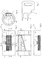
- an air duct system consists of a plurality of air outlets R 1 - R 6 , each with outlet devices 6.1 - 6.6.
- the air outlets R 1 - R 6 can have different diameters and can be round or angular in cross section. Intermediate pieces (not shown) can also be arranged between the individual air outlets R 1 - R 6 without outlet devices.
- an air outlet R has a tube 1, which has openings 2, 3 on the end face.
- this tube 1 in particular in its outer surface 4, an outlet opening 5 is provided. This is elongated and preferably in the longitudinal direction of the tube 1 from the outer surface 4 punched out.
- An outlet device is located behind this outlet opening 5 6 used.
- the outlet device 6 through the Openings 2 or 3 are pushed into tube 1 or be used through the outlet opening 5.
- the outlet device is located 6 over an arcuate edge strip 7 one Inner surface 8 of the tube 4.
- This edge strip 7 is in curved with a radius of the inner surface 8 of the tube 1, as shown in Figure 4.
- the outlet device 6 can be of a conventional type, for example. provided as a grille with lamellae 9 to keep an air flow in to direct appropriate directions.
- the slats 9 are arranged in the longitudinal direction and completely engage behind the outlet opening 5.
- the slats 9 of the outlet device 6 is a slit slide 10 to limit and / or regulate the resigned Volume flow upstream.
- Such a slider is known, for example, from EP 0 386 717 A1, to which explicit reference is made.
- Rings 11 are provided so that the outlet device 6 is fixed inside the tube 1 and is centered there.
- the outlet device 6 is inserted into the tube 1 and the rings 11.1, 11.2 are pushed through the openings 2, 3 from both sides. These press on the edge strips 7.1 and 7.2.
- clamping elements screws or similar fastening elements (not shown here) can additionally be used to secure the rings 11.1 and 11.2 and thus the outlet device 6 against twisting and slipping in the tube 1.
- fastening elements for example rivets.
- FIG. 3 it is indicated that, instead of the slats 9 or in addition to the slats 9, the outlet opening 5 can be covered by a perforated plate 12.
- FIG. 5 shows a further exemplary embodiment of an air outlet R a , in which a multiplicity of slots 13 are punched into a jacket 4.1.
- the slot slider 10 is by clip strips 16.1 and 16.2 held as indicated in Figure 4 and in the EP 0 386 717 A1 are described in more detail. These brackets 16 let the slider 10 move in the direction of the double arrow x, this shifting is easy can be done by hand when through the slats 9th is reached through.
- the amount of displacement can be based on a Scale 18 can be read.
- the outlet device 6.1 of the first air outlet R 1 is also assigned a scoop tongue 19, which projects obliquely from the rear wall 15 of the outlet device 6 into the air flow therein.
- This scoop tongue 19 ensures that only a part of the air flow is diverted to the first outlet device 6.1, so that sufficient air volume can still reach the other outlet devices 6.2-6.6.
- a measuring element 20 with which a differential pressure measurement is carried out There is in front of and behind the master grid 6.1 a measuring element 20 with which a differential pressure measurement is carried out.
- An example of a corresponding measuring element is described in DE-PS 33 36 911.9, on the is also expressly referred to, so that in in the present case a detailed description is unnecessary.
- the differential pressure is determined, the read the air volume discharged from the master grid 6.1 can be. If this air volume is too large, it must Slit slide 10 shifted slightly and thus the width a of the openings 14 can be reduced. This leads to a Throttling the air volume. The throttling happens so far until the desired amount of air emerges from the master grille 6.1.
- the width a of the openings 14 set in this way is indicated by a Setting gauge 21 (see Figure 7) scanned, the corresponding Gradations 22 has.
- this setting gauge 21 are now the openings 14 of the subsequent outlet devices 6.2 - 6.6 (slave grid) set. These thus have the same opening width a, whereby is achieved that each slave grid 6.2 - 6.6 the same amount of air flows as through the master grill 6.1. If, for example, the duct pressure changes, now only the Fan setting can be changed, the setting of the Opening widths a always remain the same, i.e. the Slotted gate valve 10 are only when installing the system adjusted, then no more.
- the following two exemplary test results testify to the extraordinarily favorable equalization of the Application of air volumes from successive Exhaust devices of an air duct system.
Abstract
Description
Die vorliegende Erfindung betrifft ein Verfahren zum Einstellen eines Luftführungssystems und insbesondere der aus Auslasseinrichtungen eines Luftführungssystems ausströmenden Luftmenge, sowie ein entsprechendes Luftführungssystem.The present invention relates to a method for adjustment of an air duct system and in particular that of Exhaust devices of an air duct system flowing out Air volume, as well as a corresponding air duct system.
Luftführungssysteme sind in vielfältiger Form und Ausführung bekannt und auf dem Markt. Es gibt eine sehr grosse Anzahl an Lüftungsgittern und Auslassen mit den verschiedensten Mengeneinstellungen. Die Mengeneinstellung wird meist bezogen auf das einzelne Lüftungsgitter vorgenommen, d.h., mit entsprechenden Messelementen findet ein Ermitteln der ausströmenden Luftmenge statt. Soll diese geändert werden, so wird die Änderung auch an jedem einzelnen Lüftungsgitter vorgenommen. Dies hat ganz erhebliche Nachteile, da jedes Gitter nach dem Einbau nachgemessen werden muss. Air guidance systems are in a variety of forms and designs known and on the market. There is a very big one Number of ventilation grilles and outlets with the most varied Quantity settings. The quantity setting is mostly based on the individual ventilation grille, i.e., it is determined with appropriate measuring elements the amount of air flowing out. Should this be changed the change will also be made to each individual ventilation grille performed. This has major drawbacks since each grid is measured after installation got to.
Hierzu wiederum sind eine erhebliche Anzahl von Messpunkten in oft nur geringem Abstand von wenigen Zentimetern erforderlich. Wenn zu einem Luftführungssystem noch eine Mehrzahl von Luftauslässen gehören, müssen diese aufeinander abgestimmt werden. Dies ist bislang eine ausserordentlich zeitaufwendige und schwierige Angelegenheit. Die Veränderung der Mengeneinstellung bei einem Gitter bewirkt gleichzeitig eine Veränderung der ausgebrachten Luftmenge bei den anderen Gittern. Wird deshalb die Luftmengeneinstellung bei einem Gitter verändert, so müssen sämtliche anderen Gitter einzeln nachreguliert werden.This in turn involves a significant number of measuring points often only a few centimeters away. If there is still a majority to an air duct system of air outlets, they must be on top of each other be coordinated. So far this has been extraordinary time-consuming and difficult matter. The change the quantity setting for a grid simultaneously a change in the amount of air discharged from the other bars. Therefore, the air volume setting at one grid changed, all other grids must individually readjusted.
Ferner ist aus der DE-AS M 14 19 V/36d, ausgelegt am
03.04.1952, eine Lüftungsanlage bekannt, bei welcher ggfs.
vorbereitete Luft durch Kanäle in einen Raum eingeführt
wird. Dabei ist dem Luftauslass ein Durchsatzmengeneinsteller
zur Regelung des Luftaustrittes vorgeschaltet.Furthermore, from DE-AS
Aus der DE-GM 18 65 251 ist eine Luftlenkjalousie zur Beund/oder Entlüftung von Räumen aufgezeigt, bei welcher rückwärtig der Luftlenkjalousie ein Schwenkdeckel bewegbar zugeordnet ist, um eine gewisse Luftaustrittsmenge zu regeln.From DE-GM 18 65 251 is an air steering blind for loading / or Ventilation of rooms shown in which A swiveling cover can be moved to the rear of the air steering blind is assigned to a certain amount of air discharge regulate.
Aus der Schweizer Zeitung ![]()
![]()
![]()
![]()
Der vorliegenden Erfindung liegt die Aufgabe zugrunde, ein Verfahren der o.g. Art zu entwickeln, mit dem die aus einer Mehrzahl von Auslasseinrichtungen ausströmende Luftmenge auf einfache Art und Weise vergleichmässigt wird. The present invention is based on the object Procedure of the above Way to develop with which from a Plurality of air flowing out of exhaust devices is evened out in a simple manner.
Zur Lösung dieser Aufgabe führt, dass eine im Luftstrom erste Auslasseinrichtung so eingestellt wird, dass eine vorbestimmte Luftmenge aus der Auslasseinrichtung ausströmt, wobei danach die Einstellung auf die nachfolgenden Auslasseinrichtungen übertragen wird.To solve this problem, one in the airflow first outlet device is set so that a predetermined amount of air from the exhaust device flows out, after which the setting on the subsequent outlet devices is transferred.
Das bedeutet, dass in einem ersten Verfahrensschritt bei einer Auslasseinrichtung die ausströmende Luftmenge auf einen gewünschten Wert eingestellt wird, wobei zum einen die Weite der Öffnung dieser Auslasseinrichtung und zum anderen die zugeführte Luftmenge durch Regulierung des Ventilators aufeinander abgestimmt werden.That means that in a first process step an outlet device, the amount of air flowing out desired value is set, on the one hand the Width of the opening of this outlet device and the other the amount of air supplied by regulating the fan be coordinated.
Es genügt dann, wenn die Weite der Öffnung einer Auslasseinrichtung zur Mengeneinstellung ermittelt und diese Weite auf die anderen Auslasseinrichtungen übertragen wird.It is sufficient if the width of the opening of an outlet device determined for quantity adjustment and this width is transferred to the other outlet devices.
Zur Ermittlung der ausströmenden Luftmenge sind vor und nach der Auslasseinrichtung Messelemente vorgesehen, die den Differenzdruck im Luftstrom ermitteln. Danach erfolgt auch eine Veränderung der Weite der Öffnung, bis der gewünschte Wert an ausströmender Luftmenge erreicht ist.To determine the amount of air flowing out, before and after the outlet device provided measuring elements that determine the differential pressure in the air flow. After that is done also change the width of the opening until the desired one Value of outflowing air volume is reached.
Vor allem hat sich herausgestellt, dass eine derartige gewünschte Vergleichmässigung dadurch erreicht wird, wenn als Referenz für alle Auslasseinrichtungen die im Luftstrom erste Einrichtung verwendet und bei dieser eine gewisse Luftmenge mittels einer Schöpfzunge abgeschöpft wird. Diese Schöpfzunge bewirkt, dass nicht mehr, wie bisher, an einer Auslasseinrichtung Mehr Luft ausströmt als an einer anderen, sondern sie führt vor allem zu der gewünschten Vergleichmässigung. Durch die Schöpfzunge wird nur ein gewünschter, ggf. vorbestimmter Anteil aus dem Luftstrom abgeschöpft und der ersten Auslasseinrichtung zugeführt. Der übrige Luftstrom kann zu den weiteren Auslasseinrichtungen weitergeleitet werden. Above all, it has been found that such a desired Uniformity is achieved if as Reference for all exhaust devices the first in the airflow Device used and with this a certain amount of air is skimmed off by means of a scoop. This Bucket causes that no longer, as before, on one Exhaust device More air flows out than at one others, but above all leads to the desired one Equalization. Through the scoop tongue only a desired, skimmed predetermined portion from the air flow if necessary and fed to the first outlet device. Of the remaining air flow can go to the other outlet devices to get redirected.
Damit ein geeignetes Abschöpfen einer bestimmten Luftmenge stattfinden kann, sollte die Schöpfzunge schräg gegen den Luftstrom angestellt sein. Ggfs. kann der Winkel der Schräg-stellung noch verändert werden. Hierdurch wird die Menge der abzuschöpfenden Luft beeinflusst.A suitable skimming of a certain amount of air can take place, the scooping tongue diagonally against the Airflow must be turned on. If necessary. can the angle of Inclination can still be changed. This will make the Affects the amount of air to be extracted.
In Versuchen hat sich herausgestellt, dass an sich die Anordnung einer Schöpfzunge an der ersten Auslasseinrichtung genügt. Jedoch ist ein ähnliches Element auch an einer der anderen Auslasseinrichtungen denkbar.Experiments have shown that the arrangement itself a scoop tongue on the first outlet device enough. However, a similar element is also on one of the other outlet devices conceivable.
In der Regel geht es nicht nur um das Einstellen von einer
Öffnung, sondern von einer Mehrzahl von Öffnungen, wobei
sich die vorliegende Erfindung vor allem auf die Auslasseinrichtungen
mit Schlitzschiebern bezieht, wie sie aus der
EP 0 386 717 bekannt sind. Durch diese Schlitzschieber
lässt sich die Luftmenge einfach und sehr genau regulieren.
Zum einen ist es möglich, die Schlitzschieber von Hand zu
verstellen, indem von vorne in die Auslasseinrichtung eingegriffen
wird und der Schlitzschieber an den Lamellen hin- und
herbewegt wird. Denkbar ist jedoch auch jede andere
mögliche Verstellung auf mechanischem, elektromotorischem,
pneumatischem oder hydraulischem Weg. Bspw. ist es auch
denkbar, dass von dem Schlitzschieber eine Zunge abragt und
aus dem Luftführungssystem herausragt und dort als Anzeige
für eine Skala dient. Eine Einstellung der Schlitzschieber
von aufeinanderfolgenden Auslasseinrichtungen erfolgt dann
anhand der gleichen Skalenwerte.Usually it's not just about hiring one
Opening, but of a plurality of openings, wherein
The present invention relates primarily to the outlet devices
with slit shutters, as they come from the
Ein derartiges erfindungsgemässes Verfahren ist vor allem
bei einem Luftführungssystem anwendbar, bei dem die Auslasseinrichtungen
nachfolgend aufeinander angeordnet sind.
Dabei spielt keine Rolle, um was für eine Auslasseinrichtung
es sich handelt und ob das Luftführungssystem einen
runden oder eckigen Querschnitt besitzt. Es hat sich herausgestellt,
dass sich bei Beaufschlagung mit unterschiedlichsten
Drücken von bspw. 10, 20 oder 30 Pa zwar die Luftmenge
verändert, die aus den Auslasseinrichtungen austritt,
jedoch verändert sich nicht die gleichmässige Austrittsmenge.
Dies ist ein ausserordentlicher Vorteil der vorliegenden
Erfindung.Such a method according to the invention is above all
applicable to an air duct system in which the exhaust devices
are arranged one after the other.
It does not matter what type of outlet device
it concerns and whether the air duct system one
has a round or angular cross-section. It turned out
that when exposed to a wide variety of
Ferner spielt keine Rolle, ob in dem Luftführungssystem Zuoder Abluft geführt wird. Es spielt auch keine Rolle, ob das Luftführungssystem einen gleichbleibenden Durchmesser oder bspw. einen gestuft abnehmenden Durchmesser aufweist. Der Erfolg der Vergleichmässigung der Luftausbringung bleibt bestehen. Furthermore, it does not matter whether Zuoder in the air duct system Exhaust air is led. It doesn't matter if the air duct system has a constant diameter or, for example, has a gradually decreasing diameter. The success of air evacuation remains.
Ein zur Durchführung des Verfahrens geeignetes
Luftführungssystem ist in Patentanspruch 5 beschrieben.
Vorteilhafte Ausgestaltungen sind in den Patentansprüche 6
bis 10 entnehmbar.A suitable one for carrying out the method
Air guidance system is described in
Ausführungsbeispiele der Erfindung sind in der Zeichnung
dargestellt und werden im folgenden näher beschrieben. Es
zeigen:
Ein erfindungsgemässes Luftführungssystem besteht gemäss Figur 1 auf einer Mehrzahl von Luftauslässen R1 - R6 mit jeweils Auslasseinrichtungen 6.1 - 6.6. Die Luftauslässe R1 - R6 können dabei unterschiedliche Durchmesser aufweisen und querschnittlich rund oder eckig sein. Zwischen den einzelnen Luftauslässen R1 - R6 können auch (nicht gezeigt) Zwischenstücke ohne Auslasseinrichtungen angeordnet sein. According to FIG. 1, an air duct system according to the invention consists of a plurality of air outlets R 1 - R 6 , each with outlet devices 6.1 - 6.6. The air outlets R 1 - R 6 can have different diameters and can be round or angular in cross section. Intermediate pieces (not shown) can also be arranged between the individual air outlets R 1 - R 6 without outlet devices.
Gemäss Figur 3 weist ein erfindungsgemässer Luftauslass R
ein Rohr 1 auf, welches stirnseitig Öffnungen 2, 3 besitzt.
In diesem Rohr 1, insbesondere in seiner Mantelfläche 4,
ist eine Auslassöffnung 5 vorgesehen. Diese ist länglich
und bevorzugt in Längsrichtung des Rohres 1 aus der Mantelfläche
4 ausgestanzt.According to FIG. 3, an air outlet R according to the invention has
a tube 1, which has
Hinter diese Auslassöffnung 5 wird eine Auslasseinrichtung
6 eingesetzt. Dabei kann die Auslasseinrichtung 6 durch die
Öffnungen 2 oder 3 in das Rohr 1 hineingeschoben werden
oder aber durch die Auslassöffnung 5 eingesetzt werden. Im
vorliegenden Ausführungsbeispiel liegt die Auslasseinrichtung
6 über einen bogenförmigen Randstreifen 7 einer
Innenfläche 8 des Rohres 4 an. Dieser Randstreifen 7 ist in
etwa mit einem Radius der Innenfläche 8 des Rohres 1 gekrümmt,
wie dies in Figur 4 dargestellt ist.An outlet device is located behind this outlet opening 5
6 used. Here, the
Die Auslasseinrichtung 6 kann herkömmlicher Art sein, bspw.
als Gitter mit Lamellen 9 versehen, um einen Luftstrom in
entsprechende Richtungen zu lenken. Im vorliegenden Ausführungsbeispiel
sind die Lamellen 9 in Längsrichtung angeordnet
und hintergreifen die Auslassöffnung 5 vollständig.
Den Lamellen 9 der Auslasseinrichtung 6 ist ein Schlitzschieber
10 zum Begrenzen und/oder Regeln des auszutretenden
Volumenstroms vorgeschaltet. Ein derartiger Schlitzschieber
ist bspw. aus der EP 0 386 717 A1 bekannt, auf die
ausdrücklich Bezug genommen wird.The
Damit die Auslasseinrichtung 6 im Inneren des Rohres 1
festliegt und dort zentriert ausgerichtet ist, sind Ringe
11 vorgesehen. Die Auslasseinrichtung 6 wird in das Rohr 1
eingeschoben und von beiden Seiten die Ringe 11.1, 11.2
durch die Öffnungen 2, 3 geschoben. Diese drücken auf die
Randstreifen 7.1 und 7.2. Zur Fixierung der Ringe 11.1,
11.2 können noch zusätzlich hier nicht gezeigte Klemmelemente,
Schrauben od. dgl. Befestigungselemente verwendet
werden, um die Ringe 11.1 und 11.2 und damit die Auslasseinrichtung
6 gegen Verdrehen und Verrutschen im Rohr 1 zu
sichern.
Ferner besteht auch die Möglichkeit, die Auslasseinrichtung
6 seitlich über Befestigungselemente, bspw. Nieten, an den
Ringen 11.1, 11.2 festzulegen.
Furthermore, there is also the possibility of fixing the
Wartung und Montage einer solchen Auslasseinrichtung 6 mit
Ringen 11 ist erheblich erleichtert. Auch können herkömmliche
Klimasysteme mit solchen Rohrabschnitten nachgerüstet
oder nachträglich mit derartigen Auslasseinrichtungen 6
versehen werden.Maintenance and assembly of such an
Gemäss Figur 3 ist angedeutet, dass anstelle der Lamellen 9
oder zusätzlich zu den Lamellen 9 die Auslassöffnung 5
durch ein Lochblech 12 abgedeckt sein kann. Ferner ist in
Figur 5 ein weiteres Ausführungsbeispiel eines Luftauslasses
Ra gezeigt, bei dem in einen Mantel 4.1 eine Vielzahl
von Schlitzen 13 eingestanzt sind. Diese Beispiele sollen
zeigen, dass für die Ausgestaltung der Auslasseinrichtung 6
eine Vielzahl von Möglichkeiten denkbar ist.According to FIG. 3, it is indicated that, instead of the
Wesentlich ist, dass eine Luftmenge, die durch die
Auslassöffnung 5 austreten soll, einstellbar ist. Dies geschieht
im vorliegenden Fall durch den Schlitzschieber 10,
wobei auch dieser andere Ausgestaltungen aufweisen kann.
Wichtig ist dabei, dass eine Weite a von Öffnungen 14 im
Schlitzschieber 10 verstellbar ist. Zu diesem Zweck sind im
vorliegenden Ausführungsbeispiel in eine Rückwand 15 der
Auslasseinrichtung 6 diese Öffnungen 14 eingeformt, während
auf der Rückwand 15 der Schlitzschieber 10 mit entsprechenden
Öffnungen aufliegt. Beim Verschieben des Schlitzschiebers
10 gelangen die jeweiligen Öffnungen von Schlitzschieber
10 und Rückwand 15 mehr oder weniger in
Übereinstimmung, so dass hierdurch die Weite a der
Öffnungen 14 verändert wird. Dabei ist es gleichgültig, von
welcher Seite der Schlitzschieber 10 der Rückwand 15
anliegt.It is essential that an amount of air through the
Der Schlitzschieber 10 wird durch Klammerstreifen 16.1 und
16.2 gehalten, wie sie in Figur 4 angedeutet und in der EP
0 386 717 A1 näher beschrieben sind. Diese Klammerstreifen
16 lassen ein Verschieben des Schlitzschiebers 10 in Richtung
des Doppelpfeiles x zu, wobei dieses Verschieben einfach
mit der Hand geschehen kann, wenn durch die Lamellen 9
hindurchgegriffen wird.The
In einem anderen Ausführungsbeispiel ist mit dem Schlitzschieber
10 eine Zunge 17 verbunden, die aus dem Rohr 1
herausragt und über die ebenfalls ein Verschieben der
Schlitzschieber 10 in Richtung des Doppelpfeiles x geschehen
kann. Dabei kann das Maß des Verschiebens anhand einer
Skala 18 abgelesen werden.In another embodiment is with the slider
10 a
Ferner ist der Auslasseinrichtung 6.1 des ersten Luftauslasses
R1 noch eine Schöpfzunge 19 zugeordnet, welche von
der Rückwand 15 der Auslasseinrichtung 6 schräg entgegen
dem Luftstrom in diesen einragt. Mit dieser Schöpfzunge 19
wird gewährleistet, dass nur ein Teil des Luftstromes zu
der ersten Auslasseinrichtung 6.1 abgeleitet wird, so dass
noch genügend Luftvolumen zu den anderen Auslasseinrichtungen
6.2 - 6.6 gelangen kann.Furthermore, the outlet device 6.1 of the first air outlet R 1 is also assigned a
Die Funktionsweise der vorliegenden Erfindung ist folgende:The operation of the present invention is as follows:
Nach dem Zusammenbau des Luftführungssystems aus den Luftauslässen
R1 - R6 werden alle Schlitzschieber 10 der einzelnen
Auslasseinrichtungen 6.1 - 6.6 so verschoben, dass
die Öffnungen 14 ihre maximale Weite a aufweisen, d.h., zu
100% geöffnet sind. Die Schöpfzunge 19 der ersten Auslasseinrichtung
6.1 (= Mastergitter) befindet sich in "Auf"-Stellung,
was bedeutet, dass sie schräg gegen den Luftstrom
in diesen einragt. After assembling the air duct system from the air outlets
R1 - R6 are all slit slides 10 of each
Exhaust devices 6.1 - 6.6 shifted so that
the
Vor und hinter dem Mastergitter 6.1 befindet sich jeweils
ein Messelement 20, mit dem eine Differenzdruckmessung
durchgeführt wird. Ein Beispiel eines entsprechenden Messelementes
ist in der DE-PS 33 36 911.9 beschrieben, auf die
ebenfalls ausdrücklich Bezug genommen wird, so dass sich im
vorliegenden Fall eine nähere Beschreibung erübrigt.There is in front of and behind the master grid 6.1
a measuring
Nunmehr wird der Druck des Luftstromes am Ventilator, der
für die Zufuhr des Luftstromes sorgt, eingestellt und am
ersten Messelement 20 vor dem Mastergitter 6.1 abgelesen.
Wird eine Änderung dieses Luftdruckes gewünscht, so muss
der Ventilator verstellt werden.Now the pressure of the air flow at the fan, the
ensures the supply of the air flow, adjusted and on
read the first measuring
Mit dem zweiten Messelement nach dem Mastergitter 6.1 wird
der Differenzdruck ermittelt, wobei aus einem Diagramm das
aus dem Mastergitter 6.1 ausgeleitete Luftvolumen abgelesen
werden kann. Ist dieses Luftvolumen zu gross, so muss der
Schlitzschieber 10 etwas verschoben und damit die Weite a
der Öffnungen 14 verringert werden. Dies führt zu einer
Drosselung der Luftmenge. Die Drosselung geschieht so weit,
bis die gewünschte Luftmenge aus dem Mastergitter 6.1 austritt.With the second measuring element after the master grid 6.1
the differential pressure is determined, the
read the air volume discharged from the master grid 6.1
can be. If this air volume is too large, it must
Slit slide 10 shifted slightly and thus the width a
of the
Die so eingestellte Weite a der Öffnungen 14 wird durch eine
Einstelllehre 21 (siehe Figur 7) abgetastet, die entsprechende
Abstufungen 22 aufweist. Mit dieser Einstelllehre
21 werden nun die Öffnungen 14 der nachfolgenden Auslasseinrichtungen
6.2 - 6.6 (Slave-Gitter) eingestellt.
Diese weisen damit die gleiche Öffnungsweite a auf, wodurch
erreicht wird, dass durch jedes Slave-Gitter 6.2 - 6.6
dieselbe Luftmenge strömt, wie durch das Mastergitter 6.1.
Ändert sich bspw. der Kanaldruck, so muss jetzt nur die
Ventilatoreinstellung verändert werden, die Einstellung der
Öffnungsweiten a bleibt immer gleich, d.h., die
Schlitzschieber 10 werden nur bei Installation der Anlage
verstellt, danach nicht mehr. Die nachfolgenden beiden
beispielhaften Versuchsergebnisse bezeugen die
ausserordentlich günstige Vergleichmässigung der
Ausbringung von Luftmengen aus aufeinander-folgenden
Auslasseinrichtungen eines Luftführungssystems.The width a of the
Claims (10)
dadurch gekennzeichnet,
dass eine im Luftstrom erste Auslasseinrichtung (6.1) so eingestellt wird, dass eine vorbestimmte Luftmenge aus der Auslasseinrichtung (6.1) ausströmt, wobei danach diese Einstellung auf die nachfolgenden Auslasseinrichtungen (6.2 - 6.6) übertragen wird.Method for setting an air duct system and in particular the amount of air flowing out of outlet devices (6.1 - 6.6) of an air duct system,
characterized,
that a first outlet device (6.1) in the air flow is set such that a predetermined amount of air flows out of the outlet device (6.1), after which this setting is transferred to the subsequent outlet devices (6.2 - 6.6).
Applications Claiming Priority (2)
| Application Number | Priority Date | Filing Date | Title |
|---|---|---|---|
| DE19710404 | 1997-03-13 | ||
| DE19710404A DE19710404C1 (en) | 1997-03-13 | 1997-03-13 | Method of adjusting air ducting system to specified outlet flow rate |
Publications (3)
| Publication Number | Publication Date |
|---|---|
| EP0864820A2 true EP0864820A2 (en) | 1998-09-16 |
| EP0864820A3 EP0864820A3 (en) | 2000-03-29 |
| EP0864820B1 EP0864820B1 (en) | 2004-01-21 |
Family
ID=7823256
Family Applications (1)
| Application Number | Title | Priority Date | Filing Date |
|---|---|---|---|
| EP98103663A Expired - Lifetime EP0864820B1 (en) | 1997-03-13 | 1998-03-03 | Method for adjusting an air circulation system |
Country Status (4)
| Country | Link |
|---|---|
| EP (1) | EP0864820B1 (en) |
| AT (1) | ATE258296T1 (en) |
| DE (2) | DE19710404C1 (en) |
| ES (1) | ES2213848T3 (en) |
Cited By (2)
| Publication number | Priority date | Publication date | Assignee | Title |
|---|---|---|---|---|
| WO2000045096A1 (en) * | 1999-01-27 | 2000-08-03 | Bo Broberg | Supply air terminal |
| CN109297091A (en) * | 2018-08-27 | 2019-02-01 | 珠海格力电器股份有限公司 | Swing flap baffle and its control method and air conditioner |
Families Citing this family (3)
| Publication number | Priority date | Publication date | Assignee | Title |
|---|---|---|---|---|
| DE202005014566U1 (en) * | 2005-09-15 | 2006-10-26 | Gurkin, Klara | Air outlet device for extension of merchantable ventilator, has air deflecting unit including curved faceplate causing air flowing out of gap to leave mutually around pipe, where faceplate is carried on recess, in which retainer is fixed |
| DE102011053300A1 (en) | 2011-09-06 | 2013-03-07 | Schako Klima Luft, Ferdinand Schad Kg | Method for controlling the ventilation of rooms |
| DE102015214410A1 (en) * | 2015-07-29 | 2017-02-02 | Bayerische Motoren Werke Aktiengesellschaft | Method for testing a ventilation system |
Citations (3)
| Publication number | Priority date | Publication date | Assignee | Title |
|---|---|---|---|---|
| DE1865251U (en) | 1962-10-31 | 1963-01-10 | Schako Metallwarenfabrik | AIR STEERING BLIND FOR VENTILATION AND / OR VENTILATION OF ROOMS WITH ADJUSTABLE SUPPLY AIR QUANTITY. |
| DE3336911A1 (en) | 1983-10-11 | 1985-04-18 | Ferdinand Schad KG, 7201 Kolbingen | DEVICE FOR MEASURING THE VOLUME FLOW OF A GAS IN A CHANNEL |
| EP0386717A2 (en) | 1989-03-09 | 1990-09-12 | Schako Metallwarenfabrik Ferdinand Schad KG | Procedure for the production of a ventilation grille |
Family Cites Families (4)
| Publication number | Priority date | Publication date | Assignee | Title |
|---|---|---|---|---|
| DE2719570A1 (en) * | 1977-05-02 | 1978-11-16 | Mabag Luft & Klimatechnik | Air conditioning system with adjustable air outlets - is readily converted for volume rate or outlet velocity regulation |
| DE2801282A1 (en) * | 1978-01-13 | 1979-07-19 | Luwa Ag | KIT FOR AIR DUCTS |
| US4258616A (en) * | 1979-10-15 | 1981-03-31 | Schako-Metallwarenfabrik, Ferdinand Schad Gmbh | Air outlet for room ventilation |
| JPS58165531U (en) * | 1982-04-28 | 1983-11-04 | 東京プレス工業株式会社 | Air conditioner with double ceiling as supply chamber |
-
1997
- 1997-03-13 DE DE19710404A patent/DE19710404C1/en not_active Expired - Fee Related
-
1998
- 1998-03-03 AT AT98103663T patent/ATE258296T1/en not_active IP Right Cessation
- 1998-03-03 ES ES98103663T patent/ES2213848T3/en not_active Expired - Lifetime
- 1998-03-03 EP EP98103663A patent/EP0864820B1/en not_active Expired - Lifetime
- 1998-03-03 DE DE59810607T patent/DE59810607D1/en not_active Expired - Fee Related
Patent Citations (3)
| Publication number | Priority date | Publication date | Assignee | Title |
|---|---|---|---|---|
| DE1865251U (en) | 1962-10-31 | 1963-01-10 | Schako Metallwarenfabrik | AIR STEERING BLIND FOR VENTILATION AND / OR VENTILATION OF ROOMS WITH ADJUSTABLE SUPPLY AIR QUANTITY. |
| DE3336911A1 (en) | 1983-10-11 | 1985-04-18 | Ferdinand Schad KG, 7201 Kolbingen | DEVICE FOR MEASURING THE VOLUME FLOW OF A GAS IN A CHANNEL |
| EP0386717A2 (en) | 1989-03-09 | 1990-09-12 | Schako Metallwarenfabrik Ferdinand Schad KG | Procedure for the production of a ventilation grille |
Non-Patent Citations (1)
| Title |
|---|
| DIE STALLATION, vol. 28, 1956, pages 150 - 154 |
Cited By (4)
| Publication number | Priority date | Publication date | Assignee | Title |
|---|---|---|---|---|
| WO2000045096A1 (en) * | 1999-01-27 | 2000-08-03 | Bo Broberg | Supply air terminal |
| US6565429B1 (en) | 1999-01-27 | 2003-05-20 | Bo Broberg | Supply air terminal |
| CN109297091A (en) * | 2018-08-27 | 2019-02-01 | 珠海格力电器股份有限公司 | Swing flap baffle and its control method and air conditioner |
| CN109297091B (en) * | 2018-08-27 | 2020-07-28 | 珠海格力电器股份有限公司 | Air sweeping baffle, control method thereof and air conditioner |
Also Published As
| Publication number | Publication date |
|---|---|
| DE59810607D1 (en) | 2004-02-26 |
| DE19710404C1 (en) | 1998-07-23 |
| EP0864820B1 (en) | 2004-01-21 |
| ES2213848T3 (en) | 2004-09-01 |
| EP0864820A3 (en) | 2000-03-29 |
| ATE258296T1 (en) | 2004-02-15 |
Similar Documents
| Publication | Publication Date | Title |
|---|---|---|
| DE602004012993T2 (en) | VENTILATION CHANNEL WITH ADJUSTABLE VENTILATION DEVICE | |
| DE2219634A1 (en) | Flow rate control and measuring device | |
| DE2108081A1 (en) | Apparatus and method for balancing flow rates in distribution systems | |
| EP0387362A1 (en) | Air conditioning system for rooms | |
| DE2708390B2 (en) | Method and device for controlling the thickness of webs | |
| DE1271951B (en) | Air diffuser | |
| EP1243450B1 (en) | Flow outlet device, especially for ventilating the vehicle interior | |
| EP0864820B1 (en) | Method for adjusting an air circulation system | |
| DE60127629T2 (en) | Air treatment and ventilation device | |
| DE2609030A1 (en) | METHOD AND DEVICE FOR GUIDING AIRSTREAMS EMITTING FROM AN AIR-PERMEABLE, IN PARTICULAR PERFORATED AREA | |
| CH628412A5 (en) | AIR DISTRIBUTION BOX FOR VENTILATION AND AIR CONDITIONING. | |
| DE2851046A1 (en) | Ventilation outlet for air conditioning system - with main and secondary air currents at reduced and increased pressure and selective direction control | |
| DE2242582C3 (en) | Air outlet device for air conditioning and ventilation systems | |
| EP2587179B1 (en) | Air passage | |
| DE2033195C3 (en) | Air outlet device for air conditioning systems | |
| DE3322075C2 (en) | Device for temperature control of the air within a room | |
| EP0816772B1 (en) | Air outlet | |
| EP0818336A2 (en) | Air nozzle for ventilation in particular for vehicle interiors | |
| EP0667496B1 (en) | Air ventilation box | |
| DE3233493C2 (en) | ||
| DE4108168C2 (en) | ||
| EP3150936B1 (en) | Air outlet and method for operating the air outlet | |
| DE2557581A1 (en) | Longitudinal ventilation supply air register - is subdivided into sections each with separate horizontally sliding control blade | |
| DE3918564A1 (en) | Air heater unit - heats air extracted from ventilator and mixes it with cooler room air | |
| DE2555885A1 (en) | CONDITIONED AIR DISPENSER IN A CENTRAL AIR CONDITIONING SYSTEM |
Legal Events
| Date | Code | Title | Description |
|---|---|---|---|
| PUAI | Public reference made under article 153(3) epc to a published international application that has entered the european phase |
Free format text: ORIGINAL CODE: 0009012 |
|
| AK | Designated contracting states |
Kind code of ref document: A2 Designated state(s): AT CH DE ES FR GB IT LI NL |
|
| AX | Request for extension of the european patent |
Free format text: AL;LT;LV;MK;RO;SI |
|
| PUAL | Search report despatched |
Free format text: ORIGINAL CODE: 0009013 |
|
| AK | Designated contracting states |
Kind code of ref document: A3 Designated state(s): AT BE CH DE DK ES FI FR GB GR IE IT LI LU MC NL PT SE |
|
| AX | Request for extension of the european patent |
Free format text: AL;LT;LV;MK;RO;SI |
|
| 17P | Request for examination filed |
Effective date: 20000414 |
|
| AKX | Designation fees paid |
Free format text: AT CH DE ES FR GB IT LI NL |
|
| 17Q | First examination report despatched |
Effective date: 20020405 |
|
| GRAP | Despatch of communication of intention to grant a patent |
Free format text: ORIGINAL CODE: EPIDOSNIGR1 |
|
| RAP1 | Party data changed (applicant data changed or rights of an application transferred) |
Owner name: SCHAKO KLIMA LUFT FERDINAND SCHAD KG |
|
| GRAS | Grant fee paid |
Free format text: ORIGINAL CODE: EPIDOSNIGR3 |
|
| GRAA | (expected) grant |
Free format text: ORIGINAL CODE: 0009210 |
|
| AK | Designated contracting states |
Kind code of ref document: B1 Designated state(s): AT CH DE ES FR GB IT LI NL |
|
| REG | Reference to a national code |
Ref country code: GB Ref legal event code: FG4D Free format text: NOT ENGLISH |
|
| REG | Reference to a national code |
Ref country code: CH Ref legal event code: NV Representative=s name: FREI PATENTANWALTSBUERO Ref country code: CH Ref legal event code: EP |
|
| GBT | Gb: translation of ep patent filed (gb section 77(6)(a)/1977) |
Effective date: 20040121 |
|
| REF | Corresponds to: |
Ref document number: 59810607 Country of ref document: DE Date of ref document: 20040226 Kind code of ref document: P |
|
| PGFP | Annual fee paid to national office [announced via postgrant information from national office to epo] |
Ref country code: NL Payment date: 20040227 Year of fee payment: 7 |
|
| PGFP | Annual fee paid to national office [announced via postgrant information from national office to epo] |
Ref country code: CH Payment date: 20040302 Year of fee payment: 7 |
|
| PGFP | Annual fee paid to national office [announced via postgrant information from national office to epo] |
Ref country code: GB Payment date: 20040303 Year of fee payment: 7 Ref country code: AT Payment date: 20040303 Year of fee payment: 7 |
|
| PGFP | Annual fee paid to national office [announced via postgrant information from national office to epo] |
Ref country code: FR Payment date: 20040310 Year of fee payment: 7 |
|
| PGFP | Annual fee paid to national office [announced via postgrant information from national office to epo] |
Ref country code: ES Payment date: 20040322 Year of fee payment: 7 |
|
| PGFP | Annual fee paid to national office [announced via postgrant information from national office to epo] |
Ref country code: DE Payment date: 20040528 Year of fee payment: 7 |
|
| ET | Fr: translation filed | ||
| REG | Reference to a national code |
Ref country code: ES Ref legal event code: FG2A Ref document number: 2213848 Country of ref document: ES Kind code of ref document: T3 |
|
| PLBE | No opposition filed within time limit |
Free format text: ORIGINAL CODE: 0009261 |
|
| STAA | Information on the status of an ep patent application or granted ep patent |
Free format text: STATUS: NO OPPOSITION FILED WITHIN TIME LIMIT |
|
| 26N | No opposition filed |
Effective date: 20041022 |
|
| PG25 | Lapsed in a contracting state [announced via postgrant information from national office to epo] |
Ref country code: IT Free format text: LAPSE BECAUSE OF NON-PAYMENT OF DUE FEES;WARNING: LAPSES OF ITALIAN PATENTS WITH EFFECTIVE DATE BEFORE 2007 MAY HAVE OCCURRED AT ANY TIME BEFORE 2007. THE CORRECT EFFECTIVE DATE MAY BE DIFFERENT FROM THE ONE RECORDED. Effective date: 20050303 Ref country code: GB Free format text: LAPSE BECAUSE OF NON-PAYMENT OF DUE FEES Effective date: 20050303 Ref country code: AT Free format text: LAPSE BECAUSE OF NON-PAYMENT OF DUE FEES Effective date: 20050303 |
|
| PG25 | Lapsed in a contracting state [announced via postgrant information from national office to epo] |
Ref country code: ES Free format text: LAPSE BECAUSE OF NON-PAYMENT OF DUE FEES Effective date: 20050304 |
|
| PG25 | Lapsed in a contracting state [announced via postgrant information from national office to epo] |
Ref country code: LI Free format text: LAPSE BECAUSE OF NON-PAYMENT OF DUE FEES Effective date: 20050331 Ref country code: CH Free format text: LAPSE BECAUSE OF NON-PAYMENT OF DUE FEES Effective date: 20050331 |
|
| PG25 | Lapsed in a contracting state [announced via postgrant information from national office to epo] |
Ref country code: NL Free format text: LAPSE BECAUSE OF NON-PAYMENT OF DUE FEES Effective date: 20051001 Ref country code: DE Free format text: LAPSE BECAUSE OF NON-PAYMENT OF DUE FEES Effective date: 20051001 |
|
| REG | Reference to a national code |
Ref country code: CH Ref legal event code: PL |
|
| GBPC | Gb: european patent ceased through non-payment of renewal fee |
Effective date: 20050303 |
|
| PG25 | Lapsed in a contracting state [announced via postgrant information from national office to epo] |
Ref country code: FR Free format text: LAPSE BECAUSE OF NON-PAYMENT OF DUE FEES Effective date: 20051130 |
|
| NLV4 | Nl: lapsed or anulled due to non-payment of the annual fee |
Effective date: 20051001 |
|
| REG | Reference to a national code |
Ref country code: FR Ref legal event code: ST Effective date: 20051130 |
|
| REG | Reference to a national code |
Ref country code: ES Ref legal event code: FD2A Effective date: 20050304 |