EP3150936B1 - Air outlet and method for operating the air outlet - Google Patents
Air outlet and method for operating the air outlet Download PDFInfo
- Publication number
- EP3150936B1 EP3150936B1 EP15187721.4A EP15187721A EP3150936B1 EP 3150936 B1 EP3150936 B1 EP 3150936B1 EP 15187721 A EP15187721 A EP 15187721A EP 3150936 B1 EP3150936 B1 EP 3150936B1
- Authority
- EP
- European Patent Office
- Prior art keywords
- air
- air outlet
- hollow body
- outlet according
- outlet openings
- Prior art date
- Legal status (The legal status is an assumption and is not a legal conclusion. Google has not performed a legal analysis and makes no representation as to the accuracy of the status listed.)
- Active
Links
- 238000000034 method Methods 0.000 title claims description 9
- 238000006073 displacement reaction Methods 0.000 claims description 27
- 238000010438 heat treatment Methods 0.000 claims description 19
- 230000001105 regulatory effect Effects 0.000 claims description 12
- 238000007906 compression Methods 0.000 claims description 8
- 230000006835 compression Effects 0.000 claims description 8
- 230000007423 decrease Effects 0.000 claims description 6
- 230000000875 corresponding effect Effects 0.000 description 23
- 230000000694 effects Effects 0.000 description 19
- 238000009423 ventilation Methods 0.000 description 17
- 238000011144 upstream manufacturing Methods 0.000 description 16
- 238000001816 cooling Methods 0.000 description 12
- 238000004146 energy storage Methods 0.000 description 10
- 230000008961 swelling Effects 0.000 description 6
- 238000010586 diagram Methods 0.000 description 3
- 239000003344 environmental pollutant Substances 0.000 description 3
- 230000006698 induction Effects 0.000 description 3
- 231100000719 pollutant Toxicity 0.000 description 3
- 238000010276 construction Methods 0.000 description 2
- 230000003068 static effect Effects 0.000 description 2
- 238000004378 air conditioning Methods 0.000 description 1
- 238000010790 dilution Methods 0.000 description 1
- 239000012895 dilution Substances 0.000 description 1
- 238000009472 formulation Methods 0.000 description 1
- 210000002837 heart atrium Anatomy 0.000 description 1
- 230000001939 inductive effect Effects 0.000 description 1
- 239000000203 mixture Substances 0.000 description 1
- 230000000717 retained effect Effects 0.000 description 1
- 230000000630 rising effect Effects 0.000 description 1
- 238000004904 shortening Methods 0.000 description 1
- 239000000243 solution Substances 0.000 description 1
Images


Classifications
-
- F—MECHANICAL ENGINEERING; LIGHTING; HEATING; WEAPONS; BLASTING
- F24—HEATING; RANGES; VENTILATING
- F24F—AIR-CONDITIONING; AIR-HUMIDIFICATION; VENTILATION; USE OF AIR CURRENTS FOR SCREENING
- F24F13/00—Details common to, or for air-conditioning, air-humidification, ventilation or use of air currents for screening
- F24F13/02—Ducting arrangements
- F24F13/06—Outlets for directing or distributing air into rooms or spaces, e.g. ceiling air diffuser
- F24F13/065—Outlets for directing or distributing air into rooms or spaces, e.g. ceiling air diffuser formed as cylindrical or spherical bodies which are rotatable
-
- F—MECHANICAL ENGINEERING; LIGHTING; HEATING; WEAPONS; BLASTING
- F24—HEATING; RANGES; VENTILATING
- F24F—AIR-CONDITIONING; AIR-HUMIDIFICATION; VENTILATION; USE OF AIR CURRENTS FOR SCREENING
- F24F11/00—Control or safety arrangements
- F24F11/70—Control systems characterised by their outputs; Constructional details thereof
- F24F11/72—Control systems characterised by their outputs; Constructional details thereof for controlling the supply of treated air, e.g. its pressure
- F24F11/74—Control systems characterised by their outputs; Constructional details thereof for controlling the supply of treated air, e.g. its pressure for controlling air flow rate or air velocity
- F24F11/745—Control systems characterised by their outputs; Constructional details thereof for controlling the supply of treated air, e.g. its pressure for controlling air flow rate or air velocity the air flow rate increasing with an increase of air-current or wind pressure
-
- F—MECHANICAL ENGINEERING; LIGHTING; HEATING; WEAPONS; BLASTING
- F24—HEATING; RANGES; VENTILATING
- F24F—AIR-CONDITIONING; AIR-HUMIDIFICATION; VENTILATION; USE OF AIR CURRENTS FOR SCREENING
- F24F13/00—Details common to, or for air-conditioning, air-humidification, ventilation or use of air currents for screening
- F24F13/02—Ducting arrangements
- F24F13/06—Outlets for directing or distributing air into rooms or spaces, e.g. ceiling air diffuser
-
- F—MECHANICAL ENGINEERING; LIGHTING; HEATING; WEAPONS; BLASTING
- F24—HEATING; RANGES; VENTILATING
- F24F—AIR-CONDITIONING; AIR-HUMIDIFICATION; VENTILATION; USE OF AIR CURRENTS FOR SCREENING
- F24F13/00—Details common to, or for air-conditioning, air-humidification, ventilation or use of air currents for screening
- F24F13/08—Air-flow control members, e.g. louvres, grilles, flaps or guide plates
- F24F13/10—Air-flow control members, e.g. louvres, grilles, flaps or guide plates movable, e.g. dampers
-
- F—MECHANICAL ENGINEERING; LIGHTING; HEATING; WEAPONS; BLASTING
- F24—HEATING; RANGES; VENTILATING
- F24F—AIR-CONDITIONING; AIR-HUMIDIFICATION; VENTILATION; USE OF AIR CURRENTS FOR SCREENING
- F24F13/00—Details common to, or for air-conditioning, air-humidification, ventilation or use of air currents for screening
- F24F13/02—Ducting arrangements
- F24F13/06—Outlets for directing or distributing air into rooms or spaces, e.g. ceiling air diffuser
- F24F2013/0608—Perforated ducts
Definitions
- the invention relates to an air outlet in the form of a hollow body, which has a jacket surface and opposing end faces, the jacket surface being provided with air outlet openings and one of the end surfaces having an air inlet, at full load the air outlet openings in an upper area of the hollow body as mixed air outlet openings and in a lower one Area of the hollow body serve as displacement air outlet openings, and the full load is defined by the size of an air volume flow of the air supplied to the air inlet.
- the known air outlets are operated with a constant air volume flow, that is, a constant volume flow of the air enters their air inlet.
- a constant air volume flow that is, a constant volume flow of the air enters their air inlet.
- different, large air outlets are available for different constant volume flows.
- five to six sizes are offered.
- an adjustment takes place, namely such that the bottom of the hollow body is opened when heated and closed when cooled.
- the warm air can get into the floor area of the room to be heated.
- cooling the cool air automatically sinks to the floor area.
- the EP 0 683 361 A2 shows such an air outlet with the features of the preamble of claim 1 and a method for operating an air outlet with the features of the preamble of claim 25.
- the invention therefore has the object of avoiding the disadvantages mentioned above.
- this object is achieved by an air outlet with the features of claim 1 and by a method for operating an air outlet with the features of claim 25.
- an adjusting device arranged inside the hollow body, which keeps the pressure of the air inside this or an upper area so high even at partial load that mixed air continues to exit from at least a portion of the air outlet openings.
- a division into a mixed air volume flow and a source volume flow should be set / regulated so that mixed air ventilation is always ensured, i.e. it works in the case of ventilation, heating and / or cooling and also in the partial load range .
- Said mixed air volume flow relates to the air that exits the air outlet openings as mixed air, so that these air outlet openings serve as mixed air outlet openings
- the said source air volume flow relates to the air that emerges as source air from the corresponding air outlet openings, so that these serve as source air outlet openings.
- the pressure inside the hollow body would also decrease in the upper area, for example to such an extent that the air emerging from the air outlet openings in this area no longer has sufficient speed to induce induction to bring about that there is no more mixed air there.
- the control device is provided in the interior of the hollow body according to the invention, which keeps the prevailing pressure of the air in the upper area of the hollow body so high, even under partial load, that mixed air continues to exit from at least a portion of the air outlet openings located there, the air distribution mentioned remains, namely the exit of mixed air from the corresponding upper area and the exit of source air from the corresponding lower area of the lateral surface of the hollow body.
- this or an upper area means that the upper area that emits mixed air at full load is the same upper, mixed air ejecting area at partial load or another upper area, for example a shortening or lengthening of the upper area, where the lower area changes accordingly.
- the adjusting device is a throttle device that is adjustable in its air passage cross section. Because the air passage cross-section can be influenced and, with the air passage cross-section appropriately closed, the pressure of the air increases in front of the throttle device (dynamic pressure), it is possible to keep the pressure of the air correspondingly high upstream of the throttle device, so that the aforementioned effect, namely the The outlet of mixed air is retained even under partial load conditions.
- the adjustment (controlled or regulated) of the air passage cross-section can take place in stages or continuously.
- the adjusting device of the invention in particular the throttle device, is always designed in all the exemplary embodiments in such a way that it does not have an absolutely closing effect even in its closed position, but rather leaves a small air passage cross-section, so that a correspondingly small proportion of the air supplied to the air inlet pass the adjusting device and in can reach the lower area of the hollow body in order to be able to exit there as swelling air.
- a closed control device / throttle device is spoken of in this application, the aforementioned state is meant.
- the adjusting device is a throttle device which can be adjusted in its position in the hollow body. Due to the throttling effect of the throttle device, there is an increase in the pressure of the air in front of it, i.e. the air pressure (dynamic pressure) rises upstream of the throttle device in the interior of the hollow cylinder, the position of the throttle device being adjusted depending on the size of the partial load. Is a partial load operation with a relatively large Volume flow before, it is sufficient to move the throttle device to a position relatively far away from the air inlet, the air pressure upstream of it still being sufficient to allow mixed air to exit from at least a portion of the air outlet openings located there. If partial load operation is set, in which a relatively small volume flow flows into the air inlet, the position of the adjustable throttle device is shifted closer to the air inlet in order to bring about the desired pressure increase for mixed air operation upstream.
- the end face opposite the air inlet is designed as a bottom, the bottom being closed or essentially closed.
- the feature of the closed bottom is intended in particular to make it clear that no adjustable bottom is absolutely necessary (although it could still be present in a special embodiment of the invention).
- the heating operation is carried out in the prior art, the floor is opened in the known air outlets. This switchover, that is to say the opening of the floor and the closing of the floor, is not required in the subject matter of the invention. Nevertheless, all modes of operation (ventilation, cooling, heating) can be carried out with the device according to the invention, both at full load and at part load, and due to the above-mentioned air distribution present in the invention is always (i.e.
- the hollow body has a longitudinal axis leading from the air inlet to the floor and that the adjustment of the Position of the throttle device takes place along the longitudinal axis of the hollow body. Since the air inlet is at one end of the hollow body and - preferably opposite - the bottom at the other end of the hollow body, the longitudinal axis runs from one end to the other end, the adjustment along the longitudinal axis will therefore lead to the Depending on the position, the throttle device is either closer to the air inlet and further away from the floor or closer to the floor and thus further away from the air inlet. Any number of intermediate positions can be approached continuously. Mixed air operation must always be implemented.
- the adjusting device is arranged between an upper and a lower zone of the hollow body.
- This statement is to be understood in such a way that the upper zone of the hollow body is formed above the actuating device, that is to say upstream of it, and the lower zone of the hollow body is formed below the actuating device, that is to say downstream of the actuating device.
- the actuating device can be displaced along the longitudinal axis of the hollow body with regard to its position, the respective zone changes with the displacement of the actuating device, for example the upper zone becomes larger and accordingly the lower zone smaller or vice versa. It is to be distinguished from these zones that the mentioned areas, i.e. the upper area and the lower area of the hollow body, mark the exit of the air type.
- section relating to the construction of the air outlet, namely in at least one Exemplary embodiment with, for example, a polygonal cylinder (upper section) and, for example, a circular cylinder (lower section).
- the adjusting device is a throttle device that can be adjusted manually, by motor and / or automatically with regard to the air passage cross section and / or the local position depending on the load condition.
- “Motorized” means that the air passage cross section and / or the spatial position is changed by means of a drive device, for example an electric drive device.
- At least one sensor is preferably provided which senses the load case, that is to say the full load or the corresponding partial load, and intervenes accordingly in a motorized manner.
- an adjustment to be made manually by the user occurs instead of the drive device.
- the adjustment with regard to the air passage cross section and / or the local position takes place without a drive device being present and without manual actuation.
- a parameter of the present load case in particular a parameter resulting from the supplied volume flow, particularly preferably the pressure inside the hollow body, is used to automatically adjust the throttle device with regard to its air passage cross-section and / or its position.
- the pressure acts on a throttle element of the throttle device and influences the setting of the air passage cross-section (in particular, for example, by acting on a throttle valve preloaded in a preferred position) and / or the pressure displaces the throttle element (in particular, for example, by relocating the throttle element preloaded in a preferred direction).
- a further development of the invention provides that the actuating device is mounted in the hollow body so that it can be displaced in position along the longitudinal axis, in particular in the direction of the floor, against the force of an energy store.
- the adjusting device is acted upon by the force of the energy accumulator and is thereby pushed into a predetermined position when there is no load, in particular an initial position provided with a stop. If the load is increased, this leads to the fact that the air pressure in the interior of the hollow body, namely on the upstream side of the actuating device, increases, with the result that as a result, the adjusting device is displaced against the force of the energy store.
- the pressure dynamic pressure
- the actuating device preferably being shifted along the longitudinal axis, specifically in the direction of the ground, i.e. downwards.
- the actuating device in accordance with the displacement of the adjusting device, at least a portion of the air outlet openings located upstream of the actuating device become mixed air outlet openings. All other air vents become displacement air vents.
- the throttle device has at least one throttle element adjustable in the air passage cross section.
- the throttle element can preferably be adjustable in the air passage cross-section manually, by motor and / or automatically, in particular against the force of an energy storage device.
- the pressure conditions are established in the hollow body, the procedure being that upstream of the throttle element, the pressure in the upper area is sufficiently high to expel mixed air from the air outlet openings located there. Due to the lower air pressure, source air is output from all other air outlet openings, in particular the air outlet openings located downstream of the throttle element.
- the pressure conditions in the hollow body can also be set in such a way that all air outlet openings located upstream of the throttle element emit mixed air, i.e. the upper area corresponds to the upper zone, and that all air outlet openings located downstream of the throttle element emit source air, that is, the lower area corresponds to the lower area Zone of the hollow body.
- the displacement with respect to the position and / or the adjustment with respect to the air passage cross section of the adjusting device, in particular the throttle element takes place by a force resulting from the dynamic pressure of the air acting on the adjusting device, in particular the throttle element, i.e. the force inside of the hollow body existing pressure conditions upstream or downstream of the actuating device.
- the throttle element is a position-displaceable plate, in particular a plate, a flap mounted pivotably on the edge, a centrally or approximately centrally mounted double flap, a diaphragm and / or a butterfly valve.
- the position-displaceable flap, in particular the plate virtually act as a baffle, with the position shifting, preferably against the force of the energy storage device, taking place due to the dynamic pressure.
- a throttling of the air flow within the hollow body is produced as a function of the flap angle. If the flap is closed, a large part of the air escapes in the upper zone of the hollow body.
- the dimensions of the flap are selected in such a way that the airway is not completely closed, but rather that air can still pass through when the flap is in the closed position.
- the procedure can also be such that the flap would completely close the airway in a closed position, but that the flap does not reach this end position, but nevertheless remains slightly open in the maximally closed position.
- the flap When the flap is fully open, it depends on the pressure profile along the longitudinal axis of the hollow body, which of the air outlet openings act as mixed air outlet openings and which act as displacement air outlet openings.
- a centrally or approximately centrally mounted double flap can be provided as a throttle element.
- a double flap is designed like a rocker.
- the mentioned screen is preferably arranged transversely to the longitudinal axis of the hollow body.
- the butterfly valve has a central or approximately central bearing point for the valve leaves.
- a tension spring, a compression spring, a torsion spring, in particular a helical spring or helical spring are used as the energy storage device and / or energy storage device.
- the compression spring can act on the position-displaceable plate.
- the compression spring is located on the downstream side of the plate.
- the above-mentioned torsion spring can act on the flap mounted pivotably on the edge or on the butterfly flap and urge the corresponding flap in the closing direction. Due to the increased pressure upstream of the respective flap, this is forced into a corresponding open position under the action of the energy storage device.
- the torsion spring can also be formed by several torsion spring elements, for example in order to act on one valve of the pair of valves.
- the energy store has a tension spring which is connected to a pliable traction means and a deflection device, in particular a deflection device deflecting by 180 °, which deflects the pliable traction means.
- the pliable traction means is attached to the upstream side of the position-displaceable plate and leads to one end of the tension spring, the other end of which is attached to the hollow body.
- a deflection by 180 ° can be provided.
- a counterweight can be attached to the traction means, which at least partially compensates for the weight of the throttle element, for example the position-shifting plate.
- the arrangement can be calibrated as a function of the balance weight.
- the hollow body - viewed along the longitudinal axis - has two sections, the upper section being formed by a polygonal cylinder, in particular an octagonal cylinder, and the lower section being formed by a circular cylinder.
- the arrangement is preferably made such that the jacket surface of the polygonal cylinder has first air outlet openings and that the circular cylinder has second air outlet openings in its jacket surface.
- the first air outlet openings differ in terms of respect to the size of the second air outlet openings.
- the arrangement is such that the second air outlet openings located in the circular cylinder decrease in size along the longitudinal axis from top to bottom, that is to say in the direction of the floor.
- the first air outlet openings which are located on the lateral surface of the polygonal cylinder, all have the same diameter.
- the diameter of the first air outlet openings is smaller than the diameter of the smallest second air outlet openings.
- the operational management always proceeds in such a way that the pressure conditions inside the hollow body are set by means of the actuating device in such a way that mixed air emerges from the air outlet openings of the polygonal cylinder and displacement air from the air outlet openings of the circular cylinder.
- an inner cylinder is arranged in the lower section, which has air passage openings.
- the air located there in the inner cylinder will therefore first pass through the air passage openings of the inner cylinder, then reach the air outlet openings of the lower section of the hollow body and exit there, namely as displacement air.
- the inner cylinder is at a radial distance from the circular cylinder.
- the inner cylinder with its Air passage openings are used in particular to smooth out the flow and in particular also to ensure that the air speed is reduced.
- the free cross-sections of the air outlet openings of at least part of the hollow body and / or the free cross-sections of the passage openings of the inner cylinder - seen in the direction of the longitudinal axis to the air inlet to the floor - decrease. This ensures that only the respective flow form (mixed air or displacement air) emerges in the upper and lower area.
- the above explanation of the effects of the free cross-sections of the air outlet openings or passage openings are also implemented by selecting a correspondingly large number of air outlet openings located in a certain area.
- an aperture ring or several aperture rings spaced apart in the direction of the longitudinal axis is / are arranged between the hollow body and the inner cylinder.
- the diaphragm rings which are perpendicular, in particular at right angles to the longitudinal axis of the hollow cylinder, prevent the air in this part from being blown out of the air outlet openings obliquely downwards. They therefore have an air guiding function in such a way that it is blown out preferably in the horizontal direction or in an approximately horizontal direction, that is to say as far as possible at right angles to the longitudinal axis or approximately at right angles to the longitudinal axis.
- the air inlet is formed on a connecting piece.
- the air outlet can be very easily connected to a pipe system of an air distribution network via the connecting piece.
- a further development of the invention provides that the throttle device, in particular at least in no-load operation, is located between the upper and lower sections of the hollow body. This has already been discussed above.
- the no-load operation characterizes the situation that no air is supplied to the air outlet.
- the throttle element designed as a plate has a circumferential edge which is at a distance from the inside of the hollow body and / or from the inside of the inner cylinder. This distance represents a constriction, i.e. a corresponding throttle point.
- the plate in particular the plate, runs transversely, in particular at right angles, to the longitudinal axis of the hollow body. This has already been discussed.
- the actuating device carries out an actuating operation or a regulating operation.
- a specification is made which, however, is not compensated for, for example in the event of pressure fluctuations in the air supplied to the air inlet.
- the actuating device is always adapted with regard to its position and / or its air passage cross-section in accordance with the current situation.
- the invention also relates to a method for operating an air outlet designed in the form of a hollow body, in particular as described above according to the various variants, wherein air supplied to an upper end of the hollow body emerges from or essentially from air outlet openings on a lateral surface of the hollow body, provided is that, depending on the size of the volume flow of the supplied air, the air pressure inside the hollow body is controlled or regulated in such a way that mixed air always emerges from the air outlet openings located in an upper area of the hollow body and preferably from the air outlet openings located in a lower area of the hollow body Air outlet openings always escape air.
- the air pressure in the hollow body is controlled or controlled by setting an air passage cross section of an adjusting device arranged inside the hollow body and / or by means of a local position setting of an adjusting device arranged displaceably inside the hollow body is regulated.
- a throttle device is preferably used as the adjusting device.
- the air outlet blows the mixed air out above the source air in such a way that the mixed air is pushed over the source air.
- This principle means that the source air is held in the floor area of the room in which the air outlet is located and thus develops its effect there, in particular the heating effect.
- the particularly warm source air can therefore not quickly rise again due to the mixed air above it, i.e. reach the ceiling of the room.
- the Figure 1 shows an area of a room 1 of a building, preferably an industrial hall.
- at least one air outlet 2 is arranged in room 1, which is arranged standing on a floor 3 of room 1.
- the air outlet 2 is supplied with air via an air line 4.
- the air line 4 is preferably installed under a ceiling 5 of the room 1 and leads from above to the air outlet 2, as from FIG Figure 1 evident.
- the air supplied to the air outlet 2 via the air line 4 is preferably processed centrally, in particular treated by, for example, having a sufficient proportion of fresh air, being cooled, heated and / or humidified.
- a similar arrangement is shown, but the air outlet 2 is not set up on the floor 3 of the room 1, but is arranged hanging in the room 1.
- the hanging device is in the Figure 2 not shown.
- the air outlet 2 is preferably located with its underside approximately two to three meters above the floor 3.
- the room air of the room 1 in the vicinity of the air outlet 2 is to be treated air-technically, so in particular ventilation and / or air-conditioning should take place, whereby preferably also a pollutant dilution takes place, i.e. the room air contaminated with pollutants Supply air to the air outlet is reduced in the pollutant content.
- a corresponding effect must always be achieved in a common zone of room 1, that is, fresh air should be provided where, for example, people are in room 1 and / or machines are set up, for example / treated air are discharged by means of the air outlet 2, with a heating effect or a cooling effect optionally being able to be implemented, that is, the air emerging from the air outlet 2 is cooler than the room air or warmer than the room air.
- the air emerging from the air outlet 2 has approximately the temperature of the room air.
- cooling it must be ensured that in the area of the floor 3, in particular in the occupied zone, temperatures that are not too low, which are perceived as unpleasant by people staying there, do not arise.
- the air outlet 2 is usually also referred to as an industrial air outlet.
- the Figure 3 illustrates the air outlet 2, which has a hollow body 6.
- the hollow body 6 has a jacket surface 7 and two opposite end faces 8 and 9.
- an air inlet 10 is formed, in particular implemented by means of a connection piece 11, which is in the Figure 3 is not shown in detail.
- the air line 4 is on the air connection piece 11 according to Figures 1 or 2 connected.
- the end face 9 forms a base 12 of the hollow body 6, the base 12 being firmly closed; the hollow body 6 accordingly has no opening at the lower end 40, i.e. in the area of the base 12, and cannot be opened there.
- the hollow body 6 has a longitudinal extent which is characterized by a longitudinal axis 13.
- the longitudinal axis 13 runs from the end face 8 to the end face 9 and represents a central axis of the hollow body 6.
- the hollow body 6 is preferably cylindrical around the longitudinal axis 13.
- the hollow body 6 has two sections 14 and 15, seen along the longitudinal axis 13, the upper section 14 being designed as a polygonal cylinder 16, in particular an octagonal cylinder 17, and the lower section 15 as a circular cylinder 18.
- the air connection piece 11 at the upper end 19 of the hollow body 6 preferably has a circular cross section.
- the various cross-sectional designs are the Figure 4 clearly visible, which shows a plan view of the end face 8 of the air outlet 2.
- the jacket wall in this section 14 of the hollow body 6 is formed by a plurality of flat wall parts 20 which are arranged at an angle to one another.
- the lower section 15 of the hollow body due to the design as a circular cylinder 18, there is a circumferential jacket wall with a corresponding radius.
- a large number of air outlet openings 21 are provided, which penetrate the jacket surface 22 of the entire air outlet 2, i.e. the entire hollow body 6, and accordingly penetrate the individual wall parts 20 in the upper section 14 and the circular cylinder 18 in the lower section 15. From the Figure 3 the air outlet openings 21 in the upper section 14 can be clearly seen.
- the air outlet openings 21 in the lower section 15 are in the Figure 3 indicated by a corresponding dashed line.
- the air outlet openings 21 in the upper section 14 all have the same cross section.
- the air outlet openings 21 in the lower section 15 are designed such that the diameter of the air outlet openings 21 located there decreases downwards, that is to say in the direction of the floor 12.
- the diameter of the air outlet openings 21 in the upper section 14 are smaller than the smallest diameter of the air outlet openings 21 in the lower section 15.
- air nozzles can also be provided instead of the air outlet openings 21, which then with regard to their Outlet cross-sections are designed according to the diameter of the air outlet openings 21 explained above. If in the course of this application a diameter of an air outlet opening 21 is mentioned, this does not mean that it has to be a circular opening, but other hole shapes can also be present which develop a corresponding effect in relation to the free cross section. If the sum of the free cross-sections of the air outlet openings 21 in the upper section is considered, then it is preferably provided that this sum is smaller than the sum of the free cross-sections in the lower section.
- an optional inner cylinder 23 which is preferably also designed as a circular cylinder and has a smaller diameter than the circular cylinder 18.
- the outer surface of the inner cylinder 23 is provided with air passage openings 24.
- the free cross-sections of the air passage openings 24 decrease in size when viewed from top to bottom, i.e. in the direction of the base 12, in particular corresponding to the air outlet openings 21 of the circular cylinder 18.
- the arrangement of diaphragm rings is also optional 55 between the circular cylinder 18 and the inner cylinder 23 ( Figure 3 ).
- an adjusting device 26 is arranged in the interior of the hollow body 6, which in the Figure 3 is only shown schematically.
- the adjusting device 26 is designed in particular as a throttle device 27, that is, it has a throttling effect on an air flow that is present in the interior of the hollow body 6 in that a volume flow of the air is supplied to the air inlet 10, which comes from the lateral surface 22, i.e. from the multitude of the air outlet openings 21 of the air outlet 2 located there and enters the room 1 in order to implement ventilation, heating and / or cooling there.
- a corresponding air pressure ratio is set upstream and downstream of the adjusting device 26, i.e. above the adjusting device 26, namely in the interior of the upper section 14, or downstream of the adjusting device 26, i.e. in the Inside the lower section 15 of the Hollow body 6.
- the mixed air 29 indicated by an arrow produces an induction effect, since it has a correspondingly high speed, that is, room air is mixed with the air emerging from these air outlet openings 21. This is where the name mixed air comes from.
- the source air 31, which is represented by a dashed arrow, is air at low speed, that is, there is no induction with the room air, but rather it forms on the side or below the air outlet 2 in room 1 corresponding spring air lake. It follows from the foregoing that the mixed air 29 emerges from the air outlet openings 21 of the polygonal cylinder 16 and that the source air 31 emerges from the air outlet openings 21 of the circular cylinder 18.
- the air outlet 2 performs a heating mode or a cooling mode as a function of the temperature of the air introduced into the air inlet 10. If there is no temperature treatment of the air supplied, ventilation takes place. It is also important how large the volume flow of the air supplied to the air inlet 10 is. If there is full load, the size of the volume flow supplied to the air inlet has a maximum value for the size of the air outlet 2. If a smaller volume flow is supplied to the air inlet 10, the air outlet 2 works in partial load operation. Partial load operation includes a large number of operating states, for example graduated possible sizes of the volume flows. However, a continuously adjustable size of the volume flow is also conceivable.
- the invention enables mixed air to be blown out in the upper region 28 of the hollow body 6 and swelling air in the lower region 32.
- the exemplary embodiment of FIG Figure 3 in the polygonal cylinder 16 and the lower region 32 lies in the embodiment of FIG Figure 3 in the case of the circular cylinder 18.
- These different types of air outflow namely on the one hand as mixed air 29 and on the other hand as source air 31, causes the mixed air 29 to push itself over the source air 31, so that the source air 31 is in the area of the floor 3 of the room 1, which is particularly important when heating is.
- the mixed air 29 prevents the source air 31 from rising, since the mixed air 29 covers the source air 31, warm air remains "trapped" in the area of the floor 3 when heated, creating a good heating effect and a pleasant indoor climate in room 1.
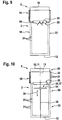
- the Figure 13 the air outlet 2 in full load operation
- the Figure 14 shows the air outlet 2 in partial load operation.
- the actuating device 26 is therefore active in that it is adjustable.
- the adjusting device 26 is adjustable with regard to its air passage cross-section and / or with regard to its local position within the hollow body 6 in order to implement the above-mentioned principle of air distribution in every operating case, i.e. under full load and also under any partial load case to maintain.
- the Figures 5 to 7 illustrate an embodiment of the air outlet 2, which corresponds to the design of the air outlet 2 of Figure 3 corresponds, the adjusting device 26 acting as a throttle device 27 being designed in this embodiment as an air flap (throttle element 54), namely a centrally mounted double flap 33.
- the double flap 33 can be adjusted manually or by means of a drive.
- the device for manual adjustment or the motorized adjustment device is not shown in detail, but can be implemented by the average person skilled in the art.
- the Figure 5 shows the double flap 33 in a fully open state. In the Figure 6 the double flap 33 is partially closed and in the Figure 7 completely closed.
- the Figure 5 illustrates the full load case, so that mixed air exits from the upper section 14 and source air exits from the lower section 15.
- the double flap 33 is closed so far, depending on the size of the partial load case, that mixed air and exiting from the lower section 15 displacement air. If there is only a very low partial load case, ie if only a very small volume flow is fed to the air outlet 2, the situation according to FIG Figure 7 occur, that is, the double flap 33 is closed and has a strong throttling effect, so that mainly air escapes from the upper section 14.
- the Figures 8 to 10 show different configurations of the actuating device 26 with a corresponding throttle element 54, namely in the case of Figure 8 as aperture 34, im Case of Figure 9 as butterfly valve 35 and in the case of Figure 10 as plate 36, in particular plate 37.
- the diaphragm 34 and the butterfly valve 35 are each arranged in a stationary manner within the volume of the hollow body 6, that is, their position cannot be changed, but depending on the load case they can bring about the throttling effect by adjusting the air passage cross-section accordingly.
- the plate 36 is mounted displaceably within the hollow body 6, so it can change its position.
- a guide rod 38 can be arranged within the hollow body 6, preferably along the longitudinal axis 13, on which the plate 36, which extends transversely, in particular at right angles, to the longitudinal axis 13, is mounted so that it is displaced in the direction of the double arrow 39 can.
- the plate 36 which extends transversely, in particular at right angles, to the longitudinal axis 13, is mounted so that it is displaced in the direction of the double arrow 39 can.
- the air pressure flow is supplied from above, a higher air pressure will set in the hollow body 6 at the top than in the hollow body 6 below, with a corresponding shift depending on the pressure, i.e. depending on the volume flow supplied and thus depending on the load case at hand the plate 36 is effected.
- it is crucial that there is a restoring force for the plate 36 as can be seen from FIG Figure 11 results.
- Figure 11 has the adjusting device 26 according to Figure 10 the displaceable plate 36, which is designed in particular as a plate 37 and can be displaced on the guide rod 38 in the direction of the double arrow 39.
- the plate 36 On the downstream side, the plate 36 has a compression spring 43 serving as an energy storage device 42, which is designed as a helical compression spring 44 and which wraps around the guide rod 38.
- One end 45 of the helical compression spring 44 is supported on the plate 36 and the other end 46 on the base 12, preferably within a receiving sleeve 47 arranged there.
- a volume flow of supplied air is fed into the upper end 19 of the hollow body 6.
- the plate 36 Due to the air pressure prevailing upstream of the plate 36, the plate 36 is directed against the force of the energy store 42 in the direction of the ground 12 moves.
- the arrangement is such that mixed air 29 emerges from the air outlet openings 21 located in the polygonal cylinder 16 and that swelling air 31 emerges from the air outlet openings 21 located in the circular cylinder 18.
- the construction can also be designed differently, for example in such a way that the helical compression spring 44 is supported on a transverse element of the guide rod 38, that is to say does not extend to the floor 12.
- FIG. 13 shows a further embodiment which corresponds to the embodiment of FIG Figure 11 corresponds and differs only in that a tension spring 49, which is designed as a helical tension spring 50, is used as the force storage device 42.
- the coil tension spring 50 is attached at one end to the housing of the air outlet 2, for example to the hollow body 6 or - if present - to the inner cylinder 23.
- the other end is connected to a counterweight 51 to which a pliable traction means 52 is attached, which leads to an upper inner area of the air outlet 2, is deflected there by 180 ° by means of a deflection device 53 and is attached to the plate 36.
- the balance weight 51 at least partially compensating for the weight of the plate 36, whereby an optimal calibration of the device can take place.
- very large rooms such as industrial halls, atriums, concert halls and so on, can be optimally ventilated or tempered, whereby operation can take place with constant volume flow or with variable volume flow and is possible under full load and / or under partial load.
- An optimal ventilation result can be achieved in all load cases with very high thermal comfort even at a short distance from the air outlet 2.
- the invention enables mixed ventilation combined with displacement ventilation in all load cases.
- the mixed ventilation preferably has inductive individual jets which emerge from the air outlet openings 21.
- an adjustable throttle element is arranged upstream in front of the air outlet 2, which throttle element can be adjusted according to the desired requirements.
- the air outlet according to the invention there are, as it were, two air outlets connected in series for ventilation, heating and / or Cooling with an interposed throttle element before, namely one air outlet for mixed air and the other air outlet for swelling air, with no complex measures for switching a flow profile or the like being necessary. Due to the invention, it is sufficient to cover the applications occurring in practice to offer only about three sizes of the air outlet.
- the hollow body is formed by two specific components, namely the polygonal cylinder 16 and the circular cylinder 18, with mixed air always exiting from the polygonal cylinder 16 and source air from the circular cylinder 18 due to the invention.
- the polygonal cylinder 16 can therefore also be referred to as a mixing head.
- the hollow body 7 does not have such a structural subdivision into two special types of cylinders, but that due to the actuating device 26 the pressure inside the hollow body 6 is controlled / regulated in such a way that mixed air in an upper part and mixed air in a lower part Part of the displacement air escapes, and this in every load case, i.e. at full load and also in any partial load case.
- the function of the air outlet openings can vary depending on the load case (once as mixed air outlet openings, another time as displacement air outlet openings).
- the Figure 15 shows a diagram.
- the volume flow V of the air supplied to the air inlet 10 is shown on the abscissa and a pressure difference ⁇ p is shown on the ordinate, the pressure difference being the pressure of the air inside the polygonal cylinder 16 (e.g. Figure 3 ) relates to the external pressure, that is to say the air pressure outside the air outlet 2.
- Two characteristic curves are shown, namely characteristic curve A, which relates to the mixed air when the actuating device 26 is closed (closed means the minimum air passage opening as well as the starting position or, for example, the starting position (if a movable actuating device 26 is present)).
- the characteristic curve B relates to the mixed air and the displacement air with the actuating device 26 open to the maximum or the actuating device 26 displaced to the maximum.
- the actuating device 26 opens further and / or it is relocated locally, so that the air quantity, which has increased beyond the previous operating point, mainly reaches the room to be ventilated via the circular cylinder 18 as displacement air.
- the proportion of air emerging from the polygonal cylinder 16 remains essentially constant.
- the area between the two characteristic curves A and B represents the control range of the arrangement.
- an air outlet in the form of a hollow body, the outer surface of which is provided with an air outlet opening, the bottom of which is closed or at least partially closed and which is provided with an air inlet opposite the bottom, with the air outlet openings in one at maximum volume flow (full load)
- the upper area of the hollow body, in which there is a static pressure p M serve as mixing outlet openings and in a lower area of the hollow body (in which there is a static pressure p Q ) as displacement air outlet openings, an adjusting device arranged inside the hollow body being provided which at reduced volume flow (partial load) keeps the pressure p M of the air inside the upper area so high (where p M is greater than p Q ) that mixed air escapes.
- a mixed ventilation form is preferably present, consisting of the output of mixed air and the output of swelling air.
- the free cross section of the sum of the air outlet openings in the upper section of the hollow body is at most half as large as the free cross section of the sum of the air outlet openings in the lower section of the hollow body.
- the adjustment range / control range of the volume flows of the air outlet relates to the ratio of the volume flows of the two types of flow (Mixed air as well as displacement air, whereby the volume flow of the mixed air is designated with V M and the volume flow of the displacement air with V Q.
- V M. / V Q 1 / 10 to 1 / 4th .
Landscapes
- Engineering & Computer Science (AREA)
- Chemical & Material Sciences (AREA)
- Combustion & Propulsion (AREA)
- Mechanical Engineering (AREA)
- General Engineering & Computer Science (AREA)
- Physics & Mathematics (AREA)
- Fluid Mechanics (AREA)
- Duct Arrangements (AREA)
Description
Die Erfindung betrifft einen Luftauslass in Form eines Hohlkörpers, der eine Mantelfläche und einander gegenüberliegende Stirnflächen aufweist, wobei die Mantelfläche mit Luftauslassöffnungen versehen ist und eine der Stirnflächen einen Lufteinlass aufweist, bei Volllast die Luftauslassöffnungen in einem oberen Bereich des Hohlkörpers als Mischluftauslassöffnungen und in einem unteren Bereich des Hohlkörpers als Quellluftauslassöffnungen dienen, und die Volllast durch die Größe eines dem Lufteinlass zugeführten Luftvolumenstroms der Luft definiert ist.The invention relates to an air outlet in the form of a hollow body, which has a jacket surface and opposing end faces, the jacket surface being provided with air outlet openings and one of the end surfaces having an air inlet, at full load the air outlet openings in an upper area of the hollow body as mixed air outlet openings and in a lower one Area of the hollow body serve as displacement air outlet openings, and the full load is defined by the size of an air volume flow of the air supplied to the air inlet.
Derartige Luftauslässe sind bekannt, sie dienen insbesondere dem Lüften, Heizen und/oder Kühlen von industriell genutzten Räumen, beispielsweise Hallen. Insbesondere gelten die vorstehenden Ausführungen auch für den Gegenstand der Erfindung.Such air outlets are known; they are used in particular for ventilation, heating and / or cooling of industrially used rooms, for example halls. In particular, the above statements also apply to the subject matter of the invention.
Die bekannten Luftauslässe werden mit konstantem Luftvolumenstrom betrieben, das heißt, in ihren Lufteinlass tritt jeweils ein konstanter Volumenstrom der Luft ein. In Abhängigkeit des Einsatzfalls stehen unterschiedliche groß ausgelegte Luftauslässe für unterschiedliche Konstant-Volumenströme zur Verfügung. Üblich sind fünf bis sechs Baugrößen, die angeboten werden. In Abhängigkeit des jeweiligen Betriebsfalls, also Lüften, Heizen oder Kühlen erfolgt eine Verstellung, nämlich derart, dass im Heizfall der Boden des Hohlkörpers geöffnet und im Kühlfall geschlossen wird. Durch das Öffnen des Bodens kann die warme Luft in den Bodenbereich des zu heizenden Raumes gelangen. Im Kühlfall sinkt die kühle Luft selbsttätig bis in den Bodenbereich.The known air outlets are operated with a constant air volume flow, that is, a constant volume flow of the air enters their air inlet. Depending on the application, different, large air outlets are available for different constant volume flows. Usually five to six sizes are offered. Depending on the particular operating mode, that is to say ventilation, heating or cooling, an adjustment takes place, namely such that the bottom of the hollow body is opened when heated and closed when cooled. By opening the floor, the warm air can get into the floor area of the room to be heated. When cooling, the cool air automatically sinks to the floor area.
Die
Bei der bekannten Lösung ist ein Antrieb zum Öffnen und Schließen des Bodens erforderlich. Ferner ist die Luftverteilung in dem zu lüftenden, zu kühlenden und/oder zu heizenden Raum verbesserungswürdig.In the known solution, a drive for opening and closing the floor is required. Furthermore, the air distribution in the room to be ventilated, cooled and / or heated is in need of improvement.
Die Erfindung hat daher die Aufgabe, die vorstehend genannten Nachteile zu vermeiden.The invention therefore has the object of avoiding the disadvantages mentioned above.
Diese Aufgabe wird erfindungsgemäß durch einen Luftauslass mit den Merkmalen von Anspruch 1 als auch durch ein Verfahren zum Betrieb eines Luftauslasses mit den Merkmalen von Anspruch 25 gelöst. Dazu ist vorgesehen, dass eine im Innern des Hohlkörpers angeordnete Stelleinrichtung, die auch bei Teillast den im Innern dieses oder eines oberen Bereichs herrschenden Druck der Luft derart groß hält, dass weiterhin Mischluft aus zumindest einem Anteil der Luftauslassöffnungen austritt. Bei der Erfindung soll auch bei einem variablen, dem Lufteinlass zugeführten Volumenstrom eine Aufteilung in einem Mischluftvolumenstrom und einem Quellvolumenstrom so eingestellt/geregelt werden, dass eine Mischluft-Lüftung immer sichergestellt ist, also im Lüftungsfall, Heizfall und/oder Kühlfall und auch im Teillastbereich funktioniert. Der genannte Mischluftvolumenstrom betrifft die Luft, die als Mischluft aus den Luftauslassöffnungen austritt, sodass diese Luftauslassöffnungen als Mischluftauslassöffnungen dienen und der genannte Quellluftvolumenstrom betrifft die Luft, die als Quellluft aus den entsprechenden Luftauslassöffnungen austreten, sodass diese als Quellluftauslassöffnungen dienen. Durch die Zuführung der Luft in den Lufteinlass ergibt sich im Innern des Hohlkörpers ein bestimmter Druck der Luft, der im Falle einer Volllast dazu führt, dass die Luft im oberen Bereich des Hohlkörpers mit hoher Geschwindigkeit aus den Luftauslassöffnungen als Luftstrahlen austritt, die Raumluft induzieren, wodurch sich eine Luftvermischung in dem zu belüftenden Raum einstellt. Hieraus resultiert die Bezeichnung "Mischluft". Nach unten hin, also weiter entfernt vom Lufteinlass des Hohlkörpers, stellt sich ein entsprechend geringerer Druck im Innern des Hohlkörpers ein, derart, dass die dort vorhandene Luft mit geringerer Geschwindigkeit aus den dort liegenden Luftauslassöffnungen austritt, nämlich induktionsfrei, sodass hier die Quellluft vorliegt. Wenn nun der Luftauslass mit einem geringerem Volumenstrom als bei Volllast gespeist wird, so würde der Druck im Innern des Hohlkörpers auch im oberen Bereich zurückgehen, beispielsweise derart weit, dass die aus den Luftauslassöffnungen dieses Bereichs austretende Luft keine hinreichende Geschwindigkeit mehr aufweist, um eine Induktion herbeizuführen, dass also dort keine Mischluft mehr vorliegt. Um dieses zu verhindern, ist erfindungsgemäß im Innern des Hohlkörpers die Stelleinrichtung vorgesehen, die den herrschenden Druck der Luft auch bei Teillast im oberen Bereich des Hohlkörpers derart groß hält, dass weiterhin Mischluft aus zumindest einem Anteil der dort gelegenen Luftauslassöffnungen austritt, es also bei der erwähnten Luftverteilung bleibt, nämlich Austritt von Mischluft aus dem entsprechenden oberen Bereich und Austritt von Quellluft aus dem entsprechenden unteren Bereich der Mantelfläche des Hohlkörpers. Die Formulierung "dieses oder eines oberen Bereichs" bedeutet, dass der obere Bereich, der bei Volllast Mischluft ausstößt, bei Teillast derselbe obere, Mischluft ausstoßende Bereich ist oder ein anderer oberer Bereich, also zum Beispiel eine Verkürzung oder Verlängerung des oberen Bereichs stattfindet, wobei sich dementsprechend der untere Bereich verändert.According to the invention, this object is achieved by an air outlet with the features of
Nach einer Weiterbildung der Erfindung ist vorgesehen, dass die Stelleinrichtung ein in ihrem Luftdurchlassquerschnitt verstellbare Drosseleinrichtung ist. Dadurch, dass der Luftdurchlassquerschnitt beeinflusst werden kann und bei entsprechend weit geschlossenem Luftdurchlassquerschnitt somit vor der Drosseleinrichtung der Druck der Luft ansteigt (Staudruck) ist es möglich, stromaufseitig der Drosseleinrichtung den Druck der Luft entsprechend groß zu halten, sodass die vorstehend genannte Wirkung, nämlich der Austritt von Mischluft auch bei Teillastzuständen erhalten bleibt. Die Verstellung (gesteuert oder geregelt) des Luftdurchlassquerschnitts kann stufenweise oder kontinuierlich erfolgen.According to a further development of the invention, it is provided that the adjusting device is a throttle device that is adjustable in its air passage cross section. Because the air passage cross-section can be influenced and, with the air passage cross-section appropriately closed, the pressure of the air increases in front of the throttle device (dynamic pressure), it is possible to keep the pressure of the air correspondingly high upstream of the throttle device, so that the aforementioned effect, namely the The outlet of mixed air is retained even under partial load conditions. The adjustment (controlled or regulated) of the air passage cross-section can take place in stages or continuously.
Die Stelleinrichtung der Erfindung, insbesondere die Drosseleinrichtung, ist bei sämtlichen Ausführungsbeispielen stets derart ausgebildet, dass sie auch in ihrer geschlossenen Stellung nicht absolut verschließend wirkt, sondern einen kleinen Luftdurchlassquerschnitt belässt, sodass ein entsprechend kleiner Anteil der dem Lufteinlass zugeführten Luft die Stelleinrichtung passieren und in den unteren Bereich des Hohlkörpers gelangen kann, um dort als Quellluft austreten zu können. Wenn also in dieser Anmeldung von einer geschlossenen Stelleinrichtung/Drosseleinrichtung gesprochen wird, so ist der vorstehend genannte Zustand gemeint.The adjusting device of the invention, in particular the throttle device, is always designed in all the exemplary embodiments in such a way that it does not have an absolutely closing effect even in its closed position, but rather leaves a small air passage cross-section, so that a correspondingly small proportion of the air supplied to the air inlet pass the adjusting device and in can reach the lower area of the hollow body in order to be able to exit there as swelling air. Thus, when a closed control device / throttle device is spoken of in this application, the aforementioned state is meant.
Vorzugsweise ist vorgesehen, dass die Stelleinrichtung eine in ihrer im Hohlkörper vorliegenden Position verstellbare Drosseleinrichtung ist. Aufgrund der Drosselwirkung der Drosseleinrichtung ergibt sich vor ihr eine Erhöhung des Drucks der Luft, also stromaufwärts der Drosseleinrichtung steigt im Innern des Hohlzylinders der Luftdruck (Staudruck), wobei in Abhängigkeit der Größe der Teillast die Position der Drosseleinrichtung verstellt wird. Liegt ein Teillastbetrieb mit relativ großem Volumenstrom vor, so reicht es aus, die Drosseleinrichtung in eine relativ weit entfernte Position zum Lufteinlass zu verlagern, wobei stromaufwärts von ihr dennoch der Luftdruck ausreicht, um Mischluft aus zumindest einem Anteil der dort liegenden Luftauslassöffnungen austreten zu lassen. Ist ein Teillastbetrieb eingestellt, bei dem ein relativ kleiner Volumenstrom in den Lufteinlass einströmt, so wird die Position der verstellbaren Drosseleinrichtung näher zum Lufteinlass hin verlagert, um stromaufwärts die gewünschte Druckerhöhung für einen Mischluftbetrieb herbeizuführen.It is preferably provided that the adjusting device is a throttle device which can be adjusted in its position in the hollow body. Due to the throttling effect of the throttle device, there is an increase in the pressure of the air in front of it, i.e. the air pressure (dynamic pressure) rises upstream of the throttle device in the interior of the hollow cylinder, the position of the throttle device being adjusted depending on the size of the partial load. Is a partial load operation with a relatively large Volume flow before, it is sufficient to move the throttle device to a position relatively far away from the air inlet, the air pressure upstream of it still being sufficient to allow mixed air to exit from at least a portion of the air outlet openings located there. If partial load operation is set, in which a relatively small volume flow flows into the air inlet, the position of the adjustable throttle device is shifted closer to the air inlet in order to bring about the desired pressure increase for mixed air operation upstream.
Selbstverständlich ist es auch möglich, eine Stelleinrichtung einzusetzen, die sowohl eine Verstellung im Luftdurchlassquerschnitt ermöglicht, als auch in der Position innerhalb des Hohlkörpers verlagerbar ist.Of course, it is also possible to use an adjusting device which enables both an adjustment in the air passage cross-section and which can be displaced in the position within the hollow body.
Nach einer Weiterbildung der Erfindung ist vorgesehen, dass die dem Lufteinlass gegenüberliegende Stirnfläche als Boden ausgebildet ist, wobei der Boden geschlossen oder im Wesentlichen geschlossen ist. Das Merkmal des geschlossenen Bodens soll insbesondere verdeutlichen, dass zwingend kein verstellbarer Boden erforderlich ist (allerdings bei einem speziellen Ausführungsbeispiel der Erfindung dennoch vorhanden sein könnte). Wird im Stand der Technik der Heizbetrieb durchgeführt, so wird bei den bekannten Luftauslässen der Boden geöffnet. Diese Umschaltung, also die Öffnung des Bodens und das Schließen des Bodens ist beim Gegenstand der Erfindung nicht erforderlich. Dennoch lassen sich alle Betriebsarten (Lüften, Kühlen, Heizen) mit der erfindungsgemäßen Vorrichtung durchführen, sowohl bei Volllast als auch bei Teillast, und aufgrund der vorstehend erwähnten, bei der Erfindung vorliegenden Luftverteilung ist stets (also in den genannten drei Betriebsarten und sowohl bei Volllast als auch bei Teillast) ein angenehmes Raumklima bewirkt. Die vorstehend erwähnte Formulierung des "im Wesentlichen geschlossenen" Bodens soll verdeutlichen, dass auch dann, wenn im Boden mindestens eine Luftaustrittsöffnung vorhanden ist, gleichwohl der erfindungsgemäße Erfolg erzielt wird und dass ein gewisser Luftaustritt im Bereich des Bodens gleichwohl zum erfindungsgemäßen Ergebnis führt. Besonders bevorzugt ist bei der Erfindung die Ausführungsform, dass der Boden komplett geschlossen ist.According to a further development of the invention it is provided that the end face opposite the air inlet is designed as a bottom, the bottom being closed or essentially closed. The feature of the closed bottom is intended in particular to make it clear that no adjustable bottom is absolutely necessary (although it could still be present in a special embodiment of the invention). If the heating operation is carried out in the prior art, the floor is opened in the known air outlets. This switchover, that is to say the opening of the floor and the closing of the floor, is not required in the subject matter of the invention. Nevertheless, all modes of operation (ventilation, cooling, heating) can be carried out with the device according to the invention, both at full load and at part load, and due to the above-mentioned air distribution present in the invention is always (i.e. in the three operating modes mentioned and both at full load as well as at part load) creates a pleasant room climate. The above-mentioned formulation of the "essentially closed" floor is intended to make it clear that even if there is at least one air outlet opening in the floor, the success according to the invention is nevertheless achieved and that a certain air outlet in the area of the floor nevertheless leads to the result according to the invention. Particularly preferred in the invention is the embodiment that the bottom is completely closed.
Nach einer Weiterbildung der Erfindung ist vorgesehen, dass der Hohlkörper eine von dem Lufteinlass zum Boden führende Längsachse aufweist und dass die Verstellung der Position der Drosseleinrichtung entlang der Längsachse des Hohlkörpers erfolgt. Da sich der Lufteinlass an dem einen Ende des Hohlkörpers befindet und - vorzugsweise gegenüberliegend - der Boden an dem anderen Ende des Hohlkörpers, die Längsachse von dem einen Ende zu dem anderen Ende verläuft, wird die Verstellung entlang der Längsachse also dazu führen, dass sich die Drosseleinrichtung stellungsabhängig entweder näher zum Lufteinlass und weiter entfernt zum Boden beziehungsweise näher zum Boden und damit weiter entfernt zum Lufteinlass befindet. Es sind beliebig viele Zwischenpositionen kontinuierlich anfahrbar. Stets ist dabei der Mischluftbetrieb zu realisieren.According to a further development of the invention it is provided that the hollow body has a longitudinal axis leading from the air inlet to the floor and that the adjustment of the Position of the throttle device takes place along the longitudinal axis of the hollow body. Since the air inlet is at one end of the hollow body and - preferably opposite - the bottom at the other end of the hollow body, the longitudinal axis runs from one end to the other end, the adjustment along the longitudinal axis will therefore lead to the Depending on the position, the throttle device is either closer to the air inlet and further away from the floor or closer to the floor and thus further away from the air inlet. Any number of intermediate positions can be approached continuously. Mixed air operation must always be implemented.
Es ist vorteilhaft, wenn die Stelleinrichtung zwischen einer oberen und einer unteren Zone des Hohlkörpers angeordnet ist. Diese Aussage ist derart zu verstehen, dass oberhalb der Stelleinrichtung, also stromaufwärts von dieser die obere Zone des Hohlkörpers ausgebildet wird und unterhalb der Stelleinrichtung, also stromabwärts der Stelleinrichtung, der untere Zone des Hohlkörpers. Ist die Stelleinrichtung im Hinblick auf ihre Ortsposition entlang der Längsachse des Hohlkörpers verlagerbar, so verändert sich mit der Verlagerung der Stelleinrichtung die jeweilige Zone, zum Beispiel wird die obere Zone dadurch größer und dementsprechend die untere Zone kleiner beziehungsweise umgekehrt. Von diesen Zonen ist zu unterscheiden, dass die erwähnten Bereiche, also der obere Bereich und der untere Bereich des Hohlkörpers den Austritt der Luftart kennzeichnet. Im oberen Bereich des Hohlkörpers tritt Mischluft aus und im unteren Bereich Quellluft. Wenn die Druckverhältnisse im Innern des Hohlkörpers derart gestaltet sind, dass oberhalb, also stromaufwärts der Stelleinrichtung der Druck in der oberen Zone nicht ausreicht, um dort überall Mischluft austreten zu lassen, so kann die obere Zone unterteilt sein in einen oberen Bereich, aus dem Mischluft austritt, und in einen darunter liegenden Teil, das zum unteren Bereich gehört, aus dem Quellluft austritt. Unterhalb der Stelleinrichtung tritt dann ebenfalls Quellluft aus. Demzufolge ändert sich die Funktion entsprechender Luftauslassöffnungen, indem sie entweder als Mischluftauslassöffnungen oder als Quellluftauslassöffnungen dienen. Von den erläuterten Begriffen "Zone" und "Bereich" ist ferner der Begriff "Abschnitt" zu unterscheiden. Wie nachstehend noch erläutert wird, ist ein oberer Abschnitt und ein unterer Abschnitt des Hohlkörpers vorhanden, wobei die Bezeichnung "Abschnitt" die Bauausführung des Luftauslasses betrifft, nämlich in mindestens einem Ausführungsbeispiel mit zum Beispiel polygonem Zylinder (oberer Abschnitt) und zum Beispiel Kreis-Zylinder (unterer Abschnitt).It is advantageous if the adjusting device is arranged between an upper and a lower zone of the hollow body. This statement is to be understood in such a way that the upper zone of the hollow body is formed above the actuating device, that is to say upstream of it, and the lower zone of the hollow body is formed below the actuating device, that is to say downstream of the actuating device. If the actuating device can be displaced along the longitudinal axis of the hollow body with regard to its position, the respective zone changes with the displacement of the actuating device, for example the upper zone becomes larger and accordingly the lower zone smaller or vice versa. It is to be distinguished from these zones that the mentioned areas, i.e. the upper area and the lower area of the hollow body, mark the exit of the air type. Mixed air exits in the upper area of the hollow body and displacement air in the lower area. If the pressure conditions inside the hollow body are such that above, i.e. upstream of the actuating device, the pressure in the upper zone is not sufficient to allow mixed air to escape everywhere, the upper zone can be divided into an upper area from which mixed air exits, and into a part below, which belongs to the lower area, from which the displacement air exits. Displacement air then also emerges below the actuating device. As a result, the function of corresponding air outlet openings changes in that they either serve as mixed air outlet openings or as displacement air outlet openings. The term “section” must also be distinguished from the terms “zone” and “area” explained. As will be explained below, there is an upper section and a lower section of the hollow body, the term "section" relating to the construction of the air outlet, namely in at least one Exemplary embodiment with, for example, a polygonal cylinder (upper section) and, for example, a circular cylinder (lower section).
Nach einer Weiterbildung der Erfindung ist vorgesehen, dass die Stelleinrichtung eine abhängig vom Lastzustand manuell, motorisch und/oder selbsttätig im Hinblick auf den Luftdurchlassquerschnitt und/oder die örtliche Position verstellbare Drosseleinrichtung ist. "Motorisch" bedeutet, dass der Luftdurchlassquerschnitt und/oder die Ortsposition mittels einer Antriebseinrichtung, beispielsweise einer elektrischen Antriebseinrichtung, verändert wird. Vorzugsweise ist mindestens ein Sensor vorgesehen, der den Lastfall, also die Volllast oder die entsprechende Teillast sensiert und dementsprechend motorisch eingreift. Im Falle einer manuellen Verstellung der Drosseleinrichtung tritt anstelle der Antriebseinrichtung eine vom Anwender manuell aufzubringende Verstellung. Im Falle der sich selbsttätig verstellbaren Drosseleinrichtung, wobei dieser Fall besonders bevorzugt ist, erfolgt die Verstellung im Hinblick auf den Luftdurchlassquerschnitt und/oder die Ortsposition ohne dass eine Antriebseinrichtung vorliegt und ohne eine manuelle Betätigung. Vielmehr wird ein Parameter des vorliegenden Lastfalls, insbesondere ein aus dem zugeführten Volumenstrom resultierender Parameter, besonders bevorzugt der sich einstellende Druck im Inneren des Hohlkörpers, verwendet, um die Verstellung der Drosseleinrichtung hinsichtlich ihres Luftdurchlassquerschnitts und/oder ihrer Ortsposition selbsttätig vorzunehmen. Hierzu wirkt der Druck auf ein Drosselelement der Drosseleinrichtung und beeinflusst die Einstellung des Luftdurchlassquerschnitts (insbesondere zum Beispiel durch Beaufschlagung einer in eine Vorzugsposition vorgespannten Drosselklappe) und/oder der Druck verlagert das Drosselelement (insbesondere zum Beispiel durch Ortsverlagerung des in eine Vorzugsrichtung vorgespannten Drosselelements).According to a further development of the invention, it is provided that the adjusting device is a throttle device that can be adjusted manually, by motor and / or automatically with regard to the air passage cross section and / or the local position depending on the load condition. “Motorized” means that the air passage cross section and / or the spatial position is changed by means of a drive device, for example an electric drive device. At least one sensor is preferably provided which senses the load case, that is to say the full load or the corresponding partial load, and intervenes accordingly in a motorized manner. In the case of manual adjustment of the throttle device, an adjustment to be made manually by the user occurs instead of the drive device. In the case of the automatically adjustable throttle device, this case being particularly preferred, the adjustment with regard to the air passage cross section and / or the local position takes place without a drive device being present and without manual actuation. Rather, a parameter of the present load case, in particular a parameter resulting from the supplied volume flow, particularly preferably the pressure inside the hollow body, is used to automatically adjust the throttle device with regard to its air passage cross-section and / or its position. For this purpose, the pressure acts on a throttle element of the throttle device and influences the setting of the air passage cross-section (in particular, for example, by acting on a throttle valve preloaded in a preferred position) and / or the pressure displaces the throttle element (in particular, for example, by relocating the throttle element preloaded in a preferred direction).
Eine Weiterbildung der Erfindung sieht vor, dass die Stelleinrichtung entgegen der Kraft eines Kraftspeichers positionsverschieblich entlang der Längsachse, insbesondere in Richtung auf den Boden, im Hohlkörper gelagert ist. Die Stelleinrichtung wird von der Kraft des Kraftspeichers beaufschlagt und dadurch bei Nulllast in eine vorgegebene Position gedrängt, insbesondere eine mit Anschlag versehene Ausgangsposition. Wird die Last erhöht, so führt dies dazu, dass der Luftdruck im Innern des Hohlkörpers, und zwar auf der stromaufwärts liegenden Seite der Stelleinrichtung ansteigt, mit der Folge, dass hierdurch die Stelleinrichtung entgegen der Kraft des Kraftspeichers verlagert wird. In Abhängigkeit des Drucks (Staudruck) wird sich somit selbsttätig eine entsprechende Position der Stelleinrichtung ergeben. Je höher der Lastfall, umso weiter verändert sich die Position von der Ausgangsposition des Nulllastfalls, wobei vorzugsweise eine Verschiebung der Stelleinrichtung entlang der Längsachse, und zwar in Richtung auf den Boden, also nach unten, erfolgt. Damit werden entsprechend der Verschiebung der Verstelleinrichtung zumindest ein Anteil der stromaufwärts zur Stelleinrichtung liegenden Luftauslassöffnungen zu Mischluftauslassöffnungen. Alle anderen Luftauslassöffnungen werden Quellluftauslassöffnungen.A further development of the invention provides that the actuating device is mounted in the hollow body so that it can be displaced in position along the longitudinal axis, in particular in the direction of the floor, against the force of an energy store. The adjusting device is acted upon by the force of the energy accumulator and is thereby pushed into a predetermined position when there is no load, in particular an initial position provided with a stop. If the load is increased, this leads to the fact that the air pressure in the interior of the hollow body, namely on the upstream side of the actuating device, increases, with the result that as a result, the adjusting device is displaced against the force of the energy store. Depending on the pressure (dynamic pressure), a corresponding position of the actuating device will thus result automatically. The higher the load case, the further the position changes from the starting position of the no-load case, with the actuating device preferably being shifted along the longitudinal axis, specifically in the direction of the ground, i.e. downwards. In this way, in accordance with the displacement of the adjusting device, at least a portion of the air outlet openings located upstream of the actuating device become mixed air outlet openings. All other air vents become displacement air vents.
Nach einer Weiterbildung der Erfindung ist vorgesehen, dass die Drosseleinrichtung mindestens ein im Luftdurchlassquerschnitt verstellbares Drosselelement aufweist. Vorzugsweise kann das Drosselelement manuell, motorisch und/oder selbsttätig, insbesondere entgegen der Kraft einer Kraftspeichervorrichtung, im Luftdurchlassquerschnitt verstellbar sein. In Abhängigkeit von der Einstellung des Luftdurchlassquerschnitts stellen sich die Druckverhältnisse im Hohlkörper ein, wobei derart vorgegangen wird, dass stromaufwärts des Drosselelements der Druck in dem oberen Bereich hinreichend groß ist, um Mischluft aus den dort liegenden Luftauslassöffnungen auszubringen. Aus allen anderen Luftauslassöffnungen, insbesondere den stromabwärts des Drosselelements gelegenen Luftauslassöffnungen wird aufgrund des niedrigeren Luftdrucks Quellluft ausgegeben. Für die Begriffe "manuell, motorisch und selbsttätig" gelten die bereits vorstehend erläuterten Definitionen. Die Druckverhältnisse im Hohlkörper können sich auch derart einstellen, dass alle stromaufwärts des Drosselelements liegenden Luftauslassöffnungen Mischluft ausstoßen, das heißt der obere Bereich entspricht der oberen Zone, und dass alle stromabwärts des Drosselelements liegenden Luftauslassöffnungen Quellluft ausgeben, das heißt, der untere Bereich entspricht der unteren Zone des Hohlkörpers.According to a further development of the invention it is provided that the throttle device has at least one throttle element adjustable in the air passage cross section. The throttle element can preferably be adjustable in the air passage cross-section manually, by motor and / or automatically, in particular against the force of an energy storage device. Depending on the setting of the air passage cross-section, the pressure conditions are established in the hollow body, the procedure being that upstream of the throttle element, the pressure in the upper area is sufficiently high to expel mixed air from the air outlet openings located there. Due to the lower air pressure, source air is output from all other air outlet openings, in particular the air outlet openings located downstream of the throttle element. The definitions already explained above apply to the terms “manual, motorized and automatic”. The pressure conditions in the hollow body can also be set in such a way that all air outlet openings located upstream of the throttle element emit mixed air, i.e. the upper area corresponds to the upper zone, and that all air outlet openings located downstream of the throttle element emit source air, that is, the lower area corresponds to the lower area Zone of the hollow body.
Wie bereits erläutert, erfolgt die Verschiebung bezüglich der Position und/oder die Verstellung bezüglich des Luftdurchlassquerschnitts der Stelleinrichtung, insbesondere des Drosselelements, durch eine aus dem auf die Stelleinrichtung, insbesondere das Drosselelement, wirkenden Staudruck der Luft resultierenden Kraft, also den im Inneren des Hohlkörpers vorliegenden Druckverhältnissen stromaufwärts beziehungsweise stromabwärts der Stelleinrichtung.As already explained, the displacement with respect to the position and / or the adjustment with respect to the air passage cross section of the adjusting device, in particular the throttle element, takes place by a force resulting from the dynamic pressure of the air acting on the adjusting device, in particular the throttle element, i.e. the force inside of the hollow body existing pressure conditions upstream or downstream of the actuating device.
Bevorzugt kann vorgesehen sein, dass das Drosselelement eine positionsverschiebliche Platte, insbesondere ein Teller, eine randseitig verschwenkbar gelagerte Klappe, eine mittig oder etwa mittig gelagerte Doppelklappe, eine Blende und/oder eine Schmetterlingsklappe ist. Die positionsverschiebliche Klappe, insbesondere der Teller, wirken quasi als Staukörper, wobei durch den Staudruck die Positionsverlagerung, vorzugsweise entgegen der Kraft des Kraftspeichers erfolgt. Bei der erwähnten randseitig verschwenkbar gelagerten Klappe wird eine Drosselung des Luftstroms innerhalb des Hohlkörpers in Abhängigkeit von dem Klappenwinkel erzeugt. Ist die Klappe geschlossen, so tritt ein Großteil der Luft in der oberen Zone des Hohlkörpers aus. Ein verbleibender, kleiner Teil der Luft tritt stromabwärts der Klappe, also in der unteren Zone aus. Die Abmessungen der Klappe sind derart gewählt, dass kein vollständiger Verschluss des Luftweges erfolgt, sondern in der geschlossenen Stellung der Klappe noch ein Luftdurchtritt stattfinden kann. Alternativ kann auch derart vorgegangen sein, dass die Klappe in einer Schließstellung zwar den Luftweg vollständig schließen würde, dass die Klappe jedoch diese Endstellung nicht erreicht, sondern in der maximal geschlossenen Stellung dennoch leicht geöffnet bleibt. Bei vollständig geöffneter Klappe kommt es auf den Druckverlauf entlang der Längsachse des Hohlkörpers an, welche der Luftauslassöffnungen als Mischluftauslassöffnungen und welche als Quellluftauslassöffnungen wirken.It can preferably be provided that the throttle element is a position-displaceable plate, in particular a plate, a flap mounted pivotably on the edge, a centrally or approximately centrally mounted double flap, a diaphragm and / or a butterfly valve. The position-displaceable flap, in particular the plate, virtually act as a baffle, with the position shifting, preferably against the force of the energy storage device, taking place due to the dynamic pressure. In the case of the above-mentioned flap pivotably mounted on the edge, a throttling of the air flow within the hollow body is produced as a function of the flap angle. If the flap is closed, a large part of the air escapes in the upper zone of the hollow body. A remaining, small part of the air escapes downstream of the flap, i.e. in the lower zone. The dimensions of the flap are selected in such a way that the airway is not completely closed, but rather that air can still pass through when the flap is in the closed position. Alternatively, the procedure can also be such that the flap would completely close the airway in a closed position, but that the flap does not reach this end position, but nevertheless remains slightly open in the maximally closed position. When the flap is fully open, it depends on the pressure profile along the longitudinal axis of the hollow body, which of the air outlet openings act as mixed air outlet openings and which act as displacement air outlet openings.
Es kann eine mittig oder etwa mittig gelagerte Doppelklappe als Drosselelement vorgesehen sein. Eine derartige Doppelklappe ist wippenartig gestaltet. Die erwähnte Blende ist vorzugsweise quer zur Längsachse des Hohlkörpers angeordnet. Die Schmetterlingsklappe weist eine mittige oder etwa mittige Lagerstelle für die Klappenblätter auf. Hinsichtlich der positionsverschieblichen Platte, insbesondere dem Teller, der randseitig verschwenkbar gelagerten Klappe und der Schmetterlingsklappe ist es denkbar, jeweils ein Kraftspeicher/eine Kraftspeichervorrichtung einzusetzen, das heißt, nur entgegen der Kraft des Kraftspeichers/der Kraftspeichervorrichtung erfolgt eine entsprechend weite Ortsverlagerung und/oder öffnet sich entsprechend weit der Luftdurchlassquerschnitt des Drosselelements.A centrally or approximately centrally mounted double flap can be provided as a throttle element. Such a double flap is designed like a rocker. The mentioned screen is preferably arranged transversely to the longitudinal axis of the hollow body. The butterfly valve has a central or approximately central bearing point for the valve leaves. With regard to the positionally displaceable plate, in particular the plate, the flap pivotably mounted on the edge and the butterfly flap, it is conceivable to use an energy storage device / energy storage device, that is, a correspondingly wide displacement and / or opening occurs only against the force of the energy storage device / energy storage device The air passage cross-section of the throttle element increases accordingly.
Insbesondere kommen als Kraftspeicher und/oder Kraftspeichervorrichtung eine Zugfeder, eine Druckfeder, eine Drehfeder, insbesondere Wendelfeder oder Schneckenfeder, zum Einsatz. So kann beispielsweise die Druckfeder die positionsverschiebliche Platte beaufschlagen. Hierbei befindet sich die Druckfeder auf der stromabwärts liegenden Seite der Platte. Die erwähnte Drehfeder kann auf die randseitig verschwenkbar gelagerte Klappe oder auf die Schmetterlingsklappe wirken und die entsprechende Klappe jeweils in Schließrichtung drängen. Durch den erhöhten Druck stromaufwärts der jeweiligen Klappe wird diese in eine entsprechende Offenstellung unter Beaufschlagung der Kraftspeichervorrichtung gedrängt. Bei der Schmetterlingsklappe kann die Drehfeder auch von mehreren Drehfederelementen gebildet sein, beispielsweise um jeweils eine Klappe des Klappenpaars zu beaufschlagen.In particular, a tension spring, a compression spring, a torsion spring, in particular a helical spring or helical spring, are used as the energy storage device and / or energy storage device. For example, the compression spring can act on the position-displaceable plate. The compression spring is located on the downstream side of the plate. The above-mentioned torsion spring can act on the flap mounted pivotably on the edge or on the butterfly flap and urge the corresponding flap in the closing direction. Due to the increased pressure upstream of the respective flap, this is forced into a corresponding open position under the action of the energy storage device. In the case of the butterfly valve, the torsion spring can also be formed by several torsion spring elements, for example in order to act on one valve of the pair of valves.
Bevorzugt ist vorgesehen, dass der Kraftspeicher eine Zugfeder aufweist, die mit einem biegeschlaffen Zugmittel und eine das biegeschlaffe Zugmittel umlenkende Umlenkvorrichtung, insbesondere um 180° umlenkende Umlenkvorrichtung, verbunden ist. Das biegeschlaffe Zugmittel ist auf der stromaufseitigen Seite der positionsverschieblichen Platte befestigt und führt zu einem Ende der Zugfeder, deren anderes Ende am Hohlkörper befestigt ist. Dabei kann eine Umlenkung um 180° vorgesehen sein. Insbesondere dann, wenn diese Umlenkung, vorzugsweise um 180°, vorgesehen ist, kann ein Ausgleichsgewicht am Zugmittel befestigt sein, das zumindest teilweise ein Ausgleich des Gewichts des Drosselelements, also beispielsweise der positionsverschieblichen Platte, vornimmt. In Abhängigkeit des Ausgleichgewichts lässt sich eine Kalibrierung der Anordnung durchführen.It is preferably provided that the energy store has a tension spring which is connected to a pliable traction means and a deflection device, in particular a deflection device deflecting by 180 °, which deflects the pliable traction means. The pliable traction means is attached to the upstream side of the position-displaceable plate and leads to one end of the tension spring, the other end of which is attached to the hollow body. A deflection by 180 ° can be provided. In particular when this deflection is provided, preferably by 180 °, a counterweight can be attached to the traction means, which at least partially compensates for the weight of the throttle element, for example the position-shifting plate. The arrangement can be calibrated as a function of the balance weight.
Nach einer Weiterbildung der Erfindung ist vorgesehen, dass der Hohlkörper - entlang der Längsachse gesehen - zwei Abschnitte aufweist, wobei der obere Abschnitt von einem polygonen Zylinder, insbesondere Acht-Eck-Zylinder, und der untere Abschnitt von einem Kreis-Zylinder gebildet ist. Die Anordnung ist dabei vorzugsweise derart getroffen, dass die Mantelfläche des polygonen Zylinders erste Luftauslassöffnungen aufweist und dass der Kreis-Zylinder zweite Luftauslassöffnungen in seiner Mantelfläche aufweist. Die ersten Luftauslassöffnungen unterscheiden sich im Hinblick auf die Größe von den zweiten Luftauslassöffnungen. Dabei ist die Anordnung derart getroffen, dass sich die im Kreis-Zylinder liegenden zweiten Luftauslassöffnungen entlang der Längsachse von oben nach unten hin, also in Richtung auf den Boden, verkleinern. Die ersten Luftauslassöffnungen, die an der Mantelfläche des polygonen Zylinders liegen, weisen alle denselben Durchmesser auf. Insbesondere ist vorgesehen, dass der Durchmesser der ersten Luftauslassöffnungen kleiner ist als der Durchmesser der kleinsten zweiten Luftauslassöffnungen. Alternativ oder zusätzlich kann die vorstehende Erläuterung zu den Wirkungen der Größen der Luftauslassöffnungen auch dadurch realisiert werden, dass die Anzahl der in einem bestimmten Flächeninhalt liegenden Luftauslassöffnungen entsprechend groß gewählt ist.According to a further development of the invention it is provided that the hollow body - viewed along the longitudinal axis - has two sections, the upper section being formed by a polygonal cylinder, in particular an octagonal cylinder, and the lower section being formed by a circular cylinder. The arrangement is preferably made such that the jacket surface of the polygonal cylinder has first air outlet openings and that the circular cylinder has second air outlet openings in its jacket surface. The first air outlet openings differ in terms of respect to the size of the second air outlet openings. The arrangement is such that the second air outlet openings located in the circular cylinder decrease in size along the longitudinal axis from top to bottom, that is to say in the direction of the floor. The first air outlet openings, which are located on the lateral surface of the polygonal cylinder, all have the same diameter. In particular, it is provided that the diameter of the first air outlet openings is smaller than the diameter of the smallest second air outlet openings. As an alternative or in addition, the above explanation of the effects of the sizes of the air outlet openings can also be implemented by selecting a correspondingly large number of air outlet openings located in a certain surface area.
Im Hinblick auf die erwähnten Luftauslassöffnungen ist anzumerken, dass bei jedem der erwähnten Ausführungsbeispiele vorgesehen sein kann, dass anstelle von Öffnungen Düsen vorgesehen sind, wobei auch bei den Düsen entsprechende Öffnungsquerschnitte vorliegen.With regard to the air outlet openings mentioned, it should be noted that in each of the exemplary embodiments mentioned it can be provided that nozzles are provided instead of openings, with corresponding opening cross-sections also being present in the nozzles.
Bezüglich der Ausführungsform mit polygonem Zylinder, insbesondere Acht-Eck-Zylinder, und Kreis-Zylinder, wird bei der Betriebsführung stets derart vorgegangen, dass mittels der Stelleinrichtung die Druckverhältnisse derart im Innern des Hohlkörpers eingestellt werden, dass aus den Luftauslassöffnungen des polygonen Zylinders Mischluft austritt und aus den Luftauslassöffnungen des Kreis-Zylinders Quellluft. Dies gilt bei Stelleinrichtungen, die im Luftdurchlassquerschnitt verstellbar sind und/oder dann, wenn die Stelleinrichtung verschieblich im Hohlkörper angeordnet ist. Ihre Stellung wird dann dementsprechend insbesondere selbsttätig eingenommen, um die genannten Luftarten aus den jeweiligen Abschnitten, also polygoner Zylinder und Kreis-Zylinder, austreten zu lassen.With regard to the embodiment with a polygonal cylinder, in particular an octagonal cylinder and a circular cylinder, the operational management always proceeds in such a way that the pressure conditions inside the hollow body are set by means of the actuating device in such a way that mixed air emerges from the air outlet openings of the polygonal cylinder and displacement air from the air outlet openings of the circular cylinder. This applies to actuating devices whose air passage cross-section is adjustable and / or when the actuating device is arranged displaceably in the hollow body. Their position is then accordingly assumed, in particular automatically, in order to allow the air types mentioned to escape from the respective sections, that is to say polygonal cylinders and circular cylinders.
Nach einer Weiterbildung der Erfindung ist vorgesehen, dass im unteren Abschnitt ein Innenzylinder angeordnet ist, der Luftdurchlassöffnungen aufweist. Die dort im Innenzylinder befindliche Luft wird also zunächst die Luftdurchlassöffnungen des Innenzylinders passieren, dann zu den Luftauslassöffnungen des unteren Abschnitts des Hohlkörpers gelangen und dort austreten, nämlich als Quellluft. Der Innenzylinder weist zum Kreis-Zylinder einen radialen Abstand auf. Der Innenzylinder mit seinen Luftdurchlassöffnungen dient insbesondere zur Strömungsvergleichsmäßigung und insbesondere auch dazu, dass ein Geschwindigkeitsabbau der Luft erfolgt.According to a further development of the invention it is provided that an inner cylinder is arranged in the lower section, which has air passage openings. The air located there in the inner cylinder will therefore first pass through the air passage openings of the inner cylinder, then reach the air outlet openings of the lower section of the hollow body and exit there, namely as displacement air. The inner cylinder is at a radial distance from the circular cylinder. The inner cylinder with its Air passage openings are used in particular to smooth out the flow and in particular also to ensure that the air speed is reduced.
Nach einer Weiterbildung der Erfindung ist vorgesehen, dass sich die freien Querschnitte der Luftauslassöffnungen von zumindest einem Teil des Hohlkörpers und/oder die freien Querschnitte der Durchlassöffnungen des Innenzylinders - in Richtung der Längsachse zum Lufteinlass zum Boden gesehen - verkleinern. Damit wird sichergestellt, dass in dem oberen und unteren Bereich nur die jeweilige Strömungsform (Mischluft oder Quellluft) austritt. Alternativ oder zusätzlich kann vorgesehen sein, dass die vorstehende Erläuterung zu den Wirkungen der freien Querschnitte der Luftauslassöffnungen beziehungsweise Durchlassöffnungen auch dadurch realisiert werden, dass die Anzahl der in einem bestimmten Flächeninhalt liegenden Luftauslassöffnungen entsprechend groß gewählt ist.According to a development of the invention it is provided that the free cross-sections of the air outlet openings of at least part of the hollow body and / or the free cross-sections of the passage openings of the inner cylinder - seen in the direction of the longitudinal axis to the air inlet to the floor - decrease. This ensures that only the respective flow form (mixed air or displacement air) emerges in the upper and lower area. As an alternative or in addition, it can be provided that the above explanation of the effects of the free cross-sections of the air outlet openings or passage openings are also implemented by selecting a correspondingly large number of air outlet openings located in a certain area.
Bevorzugt ist vorgesehen, dass zumindest in einem oberen Teil des unteren Abschnitts des Hohlkörpers ein Blendenring oder mehrere, in Richtung der Längsachse voneinander beabstandete Blendenringe zwischen dem Hohlkörper und dem Innenzylinder angeordnet ist/sind. Die Blendenringe, die quer, insbesondere rechtwinklig zur Längsachse des Hohlzylinders stehen, verhindern, dass die Luft in diesem Teil aus den Luftauslassöffnungen schräg nach unten ausgeblasen wird. Sie haben also Luftleitfunktion, derart, dass bevorzugt in horizontaler Richtung ausgeblasen wird oder in etwa horizontaler Richtung, also möglichst rechtwinklig zur Längsachse oder etwa rechtwinklig zur Längsachse.It is preferably provided that at least in an upper part of the lower section of the hollow body an aperture ring or several aperture rings spaced apart in the direction of the longitudinal axis is / are arranged between the hollow body and the inner cylinder. The diaphragm rings, which are perpendicular, in particular at right angles to the longitudinal axis of the hollow cylinder, prevent the air in this part from being blown out of the air outlet openings obliquely downwards. They therefore have an air guiding function in such a way that it is blown out preferably in the horizontal direction or in an approximately horizontal direction, that is to say as far as possible at right angles to the longitudinal axis or approximately at right angles to the longitudinal axis.
Vorzugsweise ist vorgesehen, dass der Lufteinlass an einem Anschlussstutzen gebildet ist. Über den Anschlussstutzen lässt sich der Luftauslass sehr einfach an ein Rohrsystem eines Luftverteilungsnetzes anschließen.It is preferably provided that the air inlet is formed on a connecting piece. The air outlet can be very easily connected to a pipe system of an air distribution network via the connecting piece.
Eine Weiterbildung der Erfindung sieht vor, dass sich die Drosseleinrichtung, insbesondere zumindest im Nulllastbetrieb, zwischen dem oberen und dem unteren Abschnitt des Hohlkörpers befindet. Hierauf wurde vorstehend schon eingegangen. Der Nulllastbetrieb kennzeichnet die Situation, dass dem Luftauslass keine Luft zugeführt wird.A further development of the invention provides that the throttle device, in particular at least in no-load operation, is located between the upper and lower sections of the hollow body. This has already been discussed above. The no-load operation characterizes the situation that no air is supplied to the air outlet.
Es ist vorteilhaft, wenn das als Platte, insbesondere Teller, ausgebildete Drosselelement einen Umfangsrand aufweist, der mit Abstand zur Innenseite des Hohlkörpers und/oder zur Innenseite des Innenzylinders liegt. Dieser Abstand stellt eine Verengung dar, also eine entsprechende Drosselstelle.It is advantageous if the throttle element designed as a plate, in particular a plate, has a circumferential edge which is at a distance from the inside of the hollow body and / or from the inside of the inner cylinder. This distance represents a constriction, i.e. a corresponding throttle point.
Vorzugsweise ist vorgesehen, dass die Platte, insbesondere der Teller, quer, insbesondere rechtwinklig, zur Längsachse des Hohlkörpers verläuft. Hierauf wurde schon eingegangen.It is preferably provided that the plate, in particular the plate, runs transversely, in particular at right angles, to the longitudinal axis of the hollow body. This has already been discussed.
Ferner ist es vorteilhaft, wenn die Stelleinrichtung einen Stellbetrieb oder einen Regelbetrieb durchführt. Beim Stellbetrieb erfolgt eine Vorgabe, die jedoch - beispielsweise bei Druckschwankungen der dem Lufteinlass zugeführten Luft - nicht ausgeglichen werden. Im Regelbetrieb wird die Stelleinrichtung im Hinblick auf ihre Ortsposition und/oder ihren Luftdurchlassquerschnitt entsprechend der aktuellen Situation stets angepasst.It is also advantageous if the actuating device carries out an actuating operation or a regulating operation. In the setting mode, a specification is made which, however, is not compensated for, for example in the event of pressure fluctuations in the air supplied to the air inlet. In normal operation, the actuating device is always adapted with regard to its position and / or its air passage cross-section in accordance with the current situation.
Die Erfindung betrifft ferner ein Verfahren zum Betreiben eines in Form eines Hohlkörpers ausgebildeten Luftauslasses, insbesondere wie es vorstehend nach den verschiedenen Varianten beschrieben ist, wobei einem oberen Ende des Hohlkörpers zugeführte Luft aus oder im Wesentlichen aus Luftauslassöffnungen an einer Mantelfläche des Hohlkörpers austritt, wobei vorgesehen ist, dass in Abhängigkeit der Größe des Volumenstroms der zugeführten Luft der Luftdruck im Innern des Hohlkörpers derart gesteuert oder geregelt wird, dass aus den in einem oberen Bereich des Hohlkörpers gelegenen Luftauslassöffnungen stets Mischluft austritt und vorzugsweise dass aus den in einem unteren Bereich des Hohlkörpers gelegene Luftauslassöffnungen stets Quellluft austritt.The invention also relates to a method for operating an air outlet designed in the form of a hollow body, in particular as described above according to the various variants, wherein air supplied to an upper end of the hollow body emerges from or essentially from air outlet openings on a lateral surface of the hollow body, provided is that, depending on the size of the volume flow of the supplied air, the air pressure inside the hollow body is controlled or regulated in such a way that mixed air always emerges from the air outlet openings located in an upper area of the hollow body and preferably from the air outlet openings located in a lower area of the hollow body Air outlet openings always escape air.
Ferner kann vorgesehen sein, dass der Luftdruck im Hohlkörper mittels Einstellung eines Luftdurchlassquerschnitts einer/der im Innern des Hohlkörpers angeordneten Stelleinrichtung und/oder mittels einer örtlichen Positionseinstellung einer/der im Innern des Hohlkörpers verlagerbar angeordneten Stelleinrichtung gesteuert oder geregelt wird. Als Stelleinrichtung wird vorzugsweise eine Drosseleinrichtung eingesetzt.Furthermore, it can be provided that the air pressure in the hollow body is controlled or controlled by setting an air passage cross section of an adjusting device arranged inside the hollow body and / or by means of a local position setting of an adjusting device arranged displaceably inside the hollow body is regulated. A throttle device is preferably used as the adjusting device.
Bevorzugt kann vorgesehen sein, dass in Abhängigkeit der Größe des Volumenstroms der zugeführten Luft insbesondere in einem Heizbetrieb der Luftauslass die Mischluft derart oberhalb der Quellluft ausbläst, dass sich die Mischluft über die Quellluft schiebt. Dieses Prinzip führt dazu, dass die Quellluft im Bodenbereich des Raumes, in dem sich der Luftauslass befindet, gehalten wird und somit dort ihre Wirkung, insbesondere die Heizwirkung, entfaltet. Die insbesondere warme Quellluft kann daher aufgrund der sich darüber befindenden Mischluft nicht schnell wieder aufsteigen, also an die Decke des Raumes gelangen.It can preferably be provided that, depending on the size of the volume flow of the supplied air, in particular in a heating mode, the air outlet blows the mixed air out above the source air in such a way that the mixed air is pushed over the source air. This principle means that the source air is held in the floor area of the room in which the air outlet is located and thus develops its effect there, in particular the heating effect. The particularly warm source air can therefore not quickly rise again due to the mixed air above it, i.e. reach the ceiling of the room.
Die Zeichnungen veranschaulichen die Erfindung anhand von Ausführungsbeispielen und zwar zeigt:
Figur 1- einen Bereich eines Raumes, insbesondere einer Industriehalle, in der sich ein Luftauslass, insbesondere Industrieluftauslass, befindet, wobei der Luftauslass auf den Boden des Raumes aufgestellt angeordnet ist,
Figur 2- eine der
Figur 1 entsprechende Anordnung, wobei der Luftauslass jedoch aufgehängt ist, also einen Abstand zum Boden des Raumes aufweist, Figur 3- eine Seitenansicht, teilweise geschnitten, des Luftauslasses,
Figur 4- eine Draufsicht auf eine Anschlussseite des Luftauslasses der
Figur 3 , Figuren 5bis 7- ein Längsschnitt durch den
Luftauslass gemäß Figur 3 , mit einer Stelleinrichtung nach einem ersten Ausführungsbeispiel, Figuren 8bis 10- unterschiedliche Ausführungsbeispiele des Luftauslasses gemäß
Figur 5 , wobei jedoch verschiedenartig gestaltete Stelleinrichtungen zum Einsatz gelangen, Figur 11- der Luftauslass gemäß
Figur 10 in unterschiedlichen Betriebsstellungen, Figur 12- eine Variante zum Ausführungsbeispiel der
Figur 11 , Figuren 13 und 14- den Raum gemäß
Figur 2 Figur 15- ein Diagramm betreffend das Betriebsverhalten des Luftauslasses in Abhängigkeit des zugeführten Volumenstroms der Luft.
- Figure 1
- an area of a room, in particular an industrial hall, in which an air outlet, in particular an industrial air outlet, is located, the air outlet being arranged on the floor of the room,
- Figure 2
- one of the
Figure 1 corresponding arrangement, with the air outlet being suspended, i.e. at a distance from the floor of the room, - Figure 3
- a side view, partly in section, of the air outlet,
- Figure 4
- a plan view of a connection side of the air outlet of
Figure 3 , - Figures 5 to 7
- a longitudinal section through the air outlet according to
Figure 3 , with an adjusting device according to a first embodiment, - Figures 8 to 10
- different embodiments of the air outlet according to
Figure 5 , but differently designed control devices are used, - Figure 11
- the air outlet according to
Figure 10 in different operating positions, - Figure 12
- a variant of the embodiment of
Figure 11 , - Figures 13 and 14
- the room according to
Figure 2 with air outlet in operation and indicated flow pattern at full load and at part load, and - Figure 15
- a diagram relating to the operating behavior of the air outlet as a function of the supplied volume flow of air.
Die
Die
Der Hohlkörper 6 besitzt eine Längserstreckung, die gekennzeichnet ist durch eine Längsachse 13. Die Längsachse 13 verläuft von der Stirnfläche 8 zur Stirnfläche 9 und stellt eine Mittelachse des Hohlkörpers 6 dar. Bevorzugt ist der Hohlkörper 6 um die Längsachse 13 herum zylindrisch ausgebildet. Im Ausführungsbeispiel der
Aufgrund des polygonen Zylinders 16 wird die Mantelwand in diesem Abschnitt 14 des Hohlkörpers 6 von einer Vielzahl von ebenen Wandteilen 20 gebildet, die winklig zueinander angeordnet sind. In dem unteren Abschnitt 15 des Hohlkörpers liegt aufgrund der Ausbildung als Kreis-Zylinder 18 eine mit einem entsprechenden Radius umlaufende Mantelwand vor. Es sind eine Vielzahl von Luftauslassöffnungen 21 vorgesehen, die die Mantelfläche 22 des gesamten Luftauslasses 2, also des gesamten Hohlkörpers 6, durchsetzen, demgemäß im oberen Abschnitt 14 die einzelnen Wandteile 20 und im unteren Abschnitt 15 den Kreis-Zylinder 18 durchsetzen. Aus der
Im unteren Abschnitt 15 des Hohlkörpers 6 kann sich ein optionaler Innenzylinder 23 befinden, der vorzugsweise ebenfalls als Kreis-Zylinder ausgebildet ist und einen kleineren Durchmesser aufweist als der Kreis-Zylinder 18. Die Mantelfläche des Innenzylinders 23 ist mit Luftdurchlassöffnungen 24 versehen. Optional ist auch die Möglichkeit, dass sich die freien Querschnitte der Luftdurchlassöffnungen 24 von oben nach unten gesehen, also in Richtung zum Boden 12 hin, verkleinern, insbesondere entsprechend wie bei den Luftauslassöffnungen 21 des Kreis-Zylinders 18. Optional ist auch die Anordnung von Blendenringen 55 zwischen dem Kreis-Zylinder 18 und dem Innenzylinder 23 (
In einer Zwischenzone 25, die sich zwischen dem oberen Abschnitt 14 und dem unteren Abschnitt 15 des Luftauslasses 2 befindet, ist im Innern des Hohlkörpers 6 eine Stelleinrichtung 26 angeordnet, die in der
Von besonderer Bedeutung ist, dass der Luftauslass 2 in Abhängigkeit der Temperatur der in den Lufteinlass 10 eingebrachten Luft einen Heizbetrieb oder einen Kühlbetrieb durchführt. Liegt keine Temperaturbehandlung der zugeführten Luft vor, so findet eine Lüftung statt. Ferner ist von Bedeutung, wie groß der Volumenstrom der dem Lufteinlass 10 zugeführten Luft ist. Liegt Volllast vor, so weist die Größe des dem Lufteinlass zugeführten Volumenstroms einen für die Größe des Luftauslasses 2 maximalen Wert auf. Wird ein kleinerer Volumenstrom dem Lufteinlass 10 zugeführt, so arbeitet der Luftauslass 2 im Teillast-Betrieb. Der Teillast-Betrieb beinhaltet eine Vielzahl von Betriebszuständen, beispielsweise gestufte mögliche Größen der Volumenströme. Denkbar ist jedoch auch eine kontinuierlich einstellbare Größe des Volumenstroms.It is of particular importance that the
Die Erfindung ermöglicht es, im oberen Bereich 28 des Hohlkörpers 6 Mischluft auszublasen und im unteren Bereich 32 Quellluft. Der obere Bereich 28 liegt im Ausführungsbeispiel der
Bei Volllast, also bei maximalem, dem Lufteinlass 2 zugeführten, insbesondere mittels der Luftleitung 4 zugeführten Volumenstrom der Luft tritt dieser in das Innere des Luftauslasses 2 ein und - gemäß
Die
Die
Beim Ausführungsbeispiel der
Die
Aufgrund der Erfindung lassen sich sehr große Räume, wie Industriehallen, Atrien, Konzertsäle und so weiter optimal belüften beziehungsweise temperieren, wobei der Betrieb mit konstantem Volumenstrom oder auch mit variablem Volumenstrom erfolgen kann und dabei unter Volllast und/oder unter Teillast möglich ist. Es lässt sich ein optimales Lüftungsergebnis in allen Lastfällen bei sehr hohem thermischem Komfort auch in geringem Abstand vom Luftauslass 2 erzielen. Die Erfindung ermöglicht in allen Lastfällen eine Mischlüftung kombiniert mit einer Quelllüftung. Die Mischlüftung weist vorzugsweise induktive Einzelstrahlen auf, die aus den Luftauslassöffnungen 21 austreten. Um den erwähnten Volllastfall oder Teillastfall einstellen zu können, ist es denkbar, dass stromaufwärts vor dem Luftauslass 2 ein verstellbares Drosselelement angeordnet ist, das entsprechend der gewünschten Anforderungen verstellt werden kann. Bei dem erfindungsgemäßen Luftauslass liegen quasi zwei lufttechnisch in Reihe geschaltete Luftauslässe zum Lüften, Heizen und/oder Kühlen mit zwischengeschaltetem Drosselelement vor, nämlich der eine Luftauslass für Mischluft und der andere Luftauslass für Quellluft, wobei keine aufwendigen Maßnahmen zur Umschaltung eines Strömungsprofils oder dergleichen notwendig sind. Aufgrund der Erfindung reicht es zur Abdeckung der in Praxis vorkommenden Einsatzfälle aus, nur etwa drei Baugrößen des Luftauslasses anzubieten.Due to the invention, very large rooms, such as industrial halls, atriums, concert halls and so on, can be optimally ventilated or tempered, whereby operation can take place with constant volume flow or with variable volume flow and is possible under full load and / or under partial load. An optimal ventilation result can be achieved in all load cases with very high thermal comfort even at a short distance from the
Im Hinblick auf das Ausführungsbeispiel der
Alternativ kann jedoch auch vorgesehen sein, dass der Hohlkörper 7 keine derartige konstruktive Unterteilung in zwei spezielle Zylinderarten besitzt, sondern dass aufgrund der Stelleinrichtung 26 der Druck im Innern des Hohlkörpers 6 derart gesteuert/geregelt wird, dass in einem oberen Teil Mischluft und in einem unteren Teil Quellluft austritt, und dies in jedem Lastfall, also bei Volllast und auch in jedem beliebigen Teillastfall. Dabei kann in Abhängigkeit des Lastfalls die Funktion der Luftauslassöffnungen variieren (einmal als Mischluftauslassöffnungen, ein anderes Mal als Quellluftauslassöffnungen).Alternatively, however, it can also be provided that the
Die
Aufgrund der Erfindung ergibt sich ein Luftauslass in Form eines Hohlkörpers, dessen Mantelfläche mit Luftauslassöffnung versehen ist, wobei dessen Boden geschlossen oder zumindest teilweise geschlossen ist und der mit einem dem Boden gegenüberliegenden Lufteinlass versehen ist, wobei bei maximalen Volumenstrom (Volllast) die Luftauslassöffnungen in einem oberen Bereich des Hohlkörpers, in dem ein statischer Druck pM vorliegt, als Mischauslassöffnungen und in einem unteren Bereich des Hohlkörpers (in dem ein statischer Druck pQ vorliegt) als Quellluftauslassöffnungen dienen, wobei eine im Innern des Hohlkörpers angeordnete Stelleinrichtung vorgesehen ist, die bei reduziertem Volumenstrom (Teillast) den im Innern des oberen Bereichs herrschenden Druck pM der Luft derart groß hält (wobei pM größer pQ ist), dass Mischluft austritt. Bevorzugt liegt eine Mischlüftungsform vor, bestehend aus dem Ausstoß von Mischluft und aus dem Ausstoß von Quellluft.Due to the invention, there is an air outlet in the form of a hollow body, the outer surface of which is provided with an air outlet opening, the bottom of which is closed or at least partially closed and which is provided with an air inlet opposite the bottom, with the air outlet openings in one at maximum volume flow (full load) The upper area of the hollow body, in which there is a static pressure p M , serve as mixing outlet openings and in a lower area of the hollow body (in which there is a static pressure p Q ) as displacement air outlet openings, an adjusting device arranged inside the hollow body being provided which at reduced volume flow (partial load) keeps the pressure p M of the air inside the upper area so high (where p M is greater than p Q ) that mixed air escapes. A mixed ventilation form is preferably present, consisting of the output of mixed air and the output of swelling air.
Bevorzugt ist vorgesehen, dass der freie Querschnitt der Summe der Luftauslassöffnungen im oberen Abschnitt des Hohlkörpers maximal halb so groß ist wie der freie Querschnitt der Summe der Luftauslassöffnungen im unteren Abschnitt des Hohlkörpers.It is preferably provided that the free cross section of the sum of the air outlet openings in the upper section of the hollow body is at most half as large as the free cross section of the sum of the air outlet openings in the lower section of the hollow body.
Ferner ist vorgesehen, dass der Stellbereich/Regelbereich der Volumenströme des Luftauslasses das Verhältnis der Volumenströme beider Strömungsformen betrifft (Mischluft sowie Quellluft, wobei der Volumenstrom der Mischluft mit VM bezeichnet ist und der Volumenstrom der Quellluft mit VQ. Es gilt die Beziehung: ![]()
![]()
Claims (27)
- An air outlet in the form of a hollow body, which has a jacket surface and front faces located opposite one another, wherein the jacket surface is provided with air outlet openings and one of the front faces has an air inlet, with the air outlet openings in an upper region of the hollow body serving as mixed air outlet openings and as source air outlet openings in a lower region of the hollow body at full load, and the full load is defined by the size of a volumetric flow rate of the air supplied to the air inlet, characterised by a control device (26), which is arranged in the interior of the hollow body (6) and which, even in the case of partial load, keeps the pressure of the air prevailing in the interior of this or of an upper region (28) so large that mixed air (29) still escapes from at least a portion of the air outlet openings (21).
- The air outlet according to claim 1, characterised in that the control device (26) is a throttle device (27), which is adjustable in its air passage cross-section.
- The air outlet according to any one of the preceding claims, characterised in that the control device (26) is a throttle device (27), which can be adjusted in its position, which is present in the hollow body (6).
- The air outlet according to any one of the preceding claims, characterised in that the front face (9) located opposite the air inlet (10) is formed as bottom (12), wherein the bottom (12) is closed or essentially closed.
- The air outlet according to any one of the preceding claims, characterised in that the hollow body (6) has a longitudinal axis (13) leading from the air inlet (10) to the bottom (12), and that the adjustment of the position of the throttle device (27) takes place along the longitudinal axis (13) of the hollow body (6).
- The air outlet according to any one of the preceding claims, characterised in that the control device (26) is arranged between an upper zone (58) and a lower zone (59) of the hollow body (6).
- The air outlet according to any one of the preceding claims, characterised in that the control device (26) is a throttle device (27), which, depending on the load stat, can be adjusted manually, by motor and/or automatically with regard to the air passage cross section and/or the local position.
- The air outlet according to any one of the preceding claims, characterised in that the control device (26) is supported in the hollow body (6) against the force of a force storage (42) in a position-displaceable manner along the longitudinal axis (13), in particular in the direction of the bottom (12).
- The air outlet according to any one of the preceding claims, characterised in that the throttle device (27) has at least one throttle element (54), which is adjustable in the air passage cross-section.
- The air outlet according to any one of the preceding claims, characterised in that the throttle element (54) can be adjusted manually, by motor and/or automatically in the air passage cross-section, in particular against the force of a force storage device.
- The air outlet according to any one of the preceding claims, characterised in that the displacement with respect to the position and/or the adjustment with respect to the air passage cross-section of the throttle element (54) takes place by means of a force resulting from the dynamic pressure of the air acting on the throttle element (54).
- The air outlet according to any one of the preceding claims, characterised in that the throttle element (54) is a position-displaceable plate (36), in particular a disk (37), a flap supported so as to be pivotable on the edge-side, a double flap (33) supported centrally or approximately centrally, an aperture (34) and/or a butterfly flap (35).
- The air outlet according to any one of the preceding claims, characterised in that the force storage (42) and/or the force storage device has a tension spring (49), a compression spring (43), a torsion spring, in particular helical spring or coil spring.
- The air outlet according to any one of the preceding claims, characterised in that the force storage (42) has a tension spring (49), which is connected to a flexible tension means (52) and a deflection device (53) deflecting the flexible tension means (52), in particular a deflection device (53) deflecting by 180°.
- The air outlet according to any one of the preceding claims, characterised in that the tension means (52) is connected to a balance weight (51), in particular for at least partially balancing the weight of the throttle element (54).
- The air outlet according to any one of the preceding claims, characterised in that the hollow body (6) - viewed along the longitudinal axis (13) - has two sections (14, 15), wherein the upper section (14) has a polygonal cylinder (16), in particular octagonal cylinder (17), and the lower section (15) has a circular cylinder (18).
- The air outlet according to any one of the preceding claims, characterised in that an inner cylinder (23), which has air passage openings (24), is arranged in the lower section (15).
- The air outlet according to any one of the preceding claims, characterised in that the free cross-sections of the air outlet openings (21) of at least a portion of the hollow body (6) and/or the free cross-sections of the air passage openings (24) of the inner cylinder (23) decrease - viewed in the direction of the longitudinal axis (13) from the air inlet (10) to the bottom (12).
- The air outlet according to any one of the preceding claims, characterised in that an aperture ring (55) or several aperture rings (55), which are spaced apart from one another in the direction of the longitudinal axis (13), is/are arranged between the hollow body (6) and the inner cylinder (23) at least in an upper portion of the lower section (15) of the hollow body (6).
- The air outlet according to any one of the preceding claims, characterised in that the air inlet (10) is formed on a connecting piece (11).
- The air outlet according to any one of the preceding claims, characterised in that the throttle device (27) is located between the upper (14) and the lower section (15) of the hollow body (6), in particular at least in the zero-load operation.
- The air outlet according to any one of the preceding claims, characterised in that the throttle element (54), which is formed as plate (36), in particular disk (37), has a circumferential edge, which lies at a distance from the inner side of the hollow body (6) and/or inner cylinder (23).
- The air outlet according to any one of the preceding claims, characterised in that the plate (36), in particular the disk (37), runs transversely, in particular at right angles, to the longitudinal axis (13) of the hollow body (6).
- The air outlet according to any one of the preceding claims, characterised in that the control device (26) performs a control operation or a regulating operation.
- A method for operating an air outlet formed in the shape of a hollow body, in particular according to any one or several of the preceding claims, wherein air supplied to an upper end of the hollow body escapes from or essentially from air outlet openings on a jacket surface of the hollow body, characterised in that the air pressure in the interior of the hollow body (6) is controlled or regulated in such a way as a function of the size of the volumetric flow rate of the supplied air that mixed air (29) always escapes from the air outlet openings (21) located in an upper region (28) of the hollow body (6), and preferably that source air (31) always escapes from the air outlet openings (21) located in a lower region (32) of the hollow body (6).
- The method according to claim 25, characterised in that the air pressure in the hollow body (6) is controlled or regulated by means of the setting of an air passage cross-section of a/the control device (26) arranged in the interior of the hollow body and/or by means of a local position setting of a/the control device (26) displaceably arranged in the interior of the hollow body (6).
- The method according to any one of the preceding claims, characterised in that the mixed air (29) is blown out above the source air (31) in such a way as a function of the size of the volumetric flow rate of the supplied air, in particular in a heating operation of the air outlet (2), that the mixed air (29) pushes over the source air (31).
Priority Applications (1)
| Application Number | Priority Date | Filing Date | Title |
|---|---|---|---|
| EP15187721.4A EP3150936B1 (en) | 2015-09-30 | 2015-09-30 | Air outlet and method for operating the air outlet |
Applications Claiming Priority (1)
| Application Number | Priority Date | Filing Date | Title |
|---|---|---|---|
| EP15187721.4A EP3150936B1 (en) | 2015-09-30 | 2015-09-30 | Air outlet and method for operating the air outlet |
Publications (2)
| Publication Number | Publication Date |
|---|---|
| EP3150936A1 EP3150936A1 (en) | 2017-04-05 |
| EP3150936B1 true EP3150936B1 (en) | 2020-09-02 |
Family
ID=54260623
Family Applications (1)
| Application Number | Title | Priority Date | Filing Date |
|---|---|---|---|
| EP15187721.4A Active EP3150936B1 (en) | 2015-09-30 | 2015-09-30 | Air outlet and method for operating the air outlet |
Country Status (1)
| Country | Link |
|---|---|
| EP (1) | EP3150936B1 (en) |
Families Citing this family (1)
| Publication number | Priority date | Publication date | Assignee | Title |
|---|---|---|---|---|
| CN112432337B (en) * | 2020-11-27 | 2021-11-16 | 珠海格力电器股份有限公司 | Air port position regulating method and device, air conditioner and storage medium |
Family Cites Families (3)
| Publication number | Priority date | Publication date | Assignee | Title |
|---|---|---|---|---|
| US5360373A (en) * | 1993-01-08 | 1994-11-01 | H. Krantz-Tkt Gmbh | Upwelling-air distributor for air-conditioning systems |
| DE4417715C1 (en) * | 1994-05-20 | 1995-12-07 | Bree Hartmut | Air outlet |
| DE29502396U1 (en) * | 1995-02-15 | 1995-04-20 | Trox Gmbh Geb | Displacement air passage |
-
2015
- 2015-09-30 EP EP15187721.4A patent/EP3150936B1/en active Active
Non-Patent Citations (1)
| Title |
|---|
| None * |
Also Published As
| Publication number | Publication date |
|---|---|
| EP3150936A1 (en) | 2017-04-05 |
Similar Documents
| Publication | Publication Date | Title |
|---|---|---|
| DE602005001059T2 (en) | Device for controlling the air flow of a ventilation system | |
| DE3918218C2 (en) | Air outlet | |
| DE10157406B4 (en) | incoming air | |
| EP2858804B1 (en) | Device for cooling a film, comprising a lever system | |
| DD141562A5 (en) | AIR OUTLET | |
| EP3150936B1 (en) | Air outlet and method for operating the air outlet | |
| DE19543018A1 (en) | Regulator for gas burner and its nozzle | |
| DE202006007846U1 (en) | Air outlet, especially ceiling air outlet, has housing walls extending at acute angle of between 3 and 25 degrees to perforated plate, and preferably between 7 and 15 degrees | |
| DE60117162T2 (en) | VALVE FOR VARIABLE FLOWS, FIRE FLAP AND COMBINED FIRE FLAP AND VALVE FOR VARIABLE FLOWS | |
| DE3410078A1 (en) | Ceiling air outlet for high rooms | |
| EP2587179B1 (en) | Air passage | |
| EP3596403A1 (en) | Displaced air outlet | |
| EP2498016B1 (en) | Air conditioning device for venting, heating or cooling a room in a building | |
| DE202015105168U1 (en) | air outlet | |
| DE1915434A1 (en) | Flow media mixing device | |
| EP2860467A1 (en) | Air outlet | |
| EP1167893A2 (en) | Apparatus for heating or cooling of a liquid medium, more particularly solar collector , and valve for use in such an apparatus | |
| EP0864820B1 (en) | Method for adjusting an air circulation system | |
| EP3730906A1 (en) | Volume flow regulator and method for controlling a volume flow | |
| DE10230343A1 (en) | radiator valve | |
| DE102010024342B4 (en) | Control valve for a steam turbine | |
| DE3233493C2 (en) | ||
| DE1803360C3 (en) | Arrangement for pressure control of flowing media | |
| DE4443352A1 (en) | Device for controlling a flow, in particular a valve | |
| EP3246483A2 (en) | Valve for a building envelope element and building envelope element comprising a valve |
Legal Events
| Date | Code | Title | Description |
|---|---|---|---|
| PUAI | Public reference made under article 153(3) epc to a published international application that has entered the european phase |
Free format text: ORIGINAL CODE: 0009012 |
|
| STAA | Information on the status of an ep patent application or granted ep patent |
Free format text: STATUS: THE APPLICATION HAS BEEN PUBLISHED |
|
| AK | Designated contracting states |
Kind code of ref document: A1 Designated state(s): AL AT BE BG CH CY CZ DE DK EE ES FI FR GB GR HR HU IE IS IT LI LT LU LV MC MK MT NL NO PL PT RO RS SE SI SK SM TR |
|
| AX | Request for extension of the european patent |
Extension state: BA ME |
|
| STAA | Information on the status of an ep patent application or granted ep patent |
Free format text: STATUS: REQUEST FOR EXAMINATION WAS MADE |
|
| 17P | Request for examination filed |
Effective date: 20171005 |
|
| RBV | Designated contracting states (corrected) |
Designated state(s): AL AT BE BG CH CY CZ DE DK EE ES FI FR GB GR HR HU IE IS IT LI LT LU LV MC MK MT NL NO PL PT RO RS SE SI SK SM TR |
|
| REG | Reference to a national code |
Ref country code: DE Ref legal event code: R079 Ref document number: 502015013368 Country of ref document: DE Free format text: PREVIOUS MAIN CLASS: F24F0011020000 Ipc: F24F0013060000 |
|
| GRAP | Despatch of communication of intention to grant a patent |
Free format text: ORIGINAL CODE: EPIDOSNIGR1 |
|
| STAA | Information on the status of an ep patent application or granted ep patent |
Free format text: STATUS: GRANT OF PATENT IS INTENDED |
|
| RIC1 | Information provided on ipc code assigned before grant |
Ipc: F24F 11/72 20180101ALI20200110BHEP Ipc: F24F 13/06 20060101AFI20200110BHEP Ipc: F24F 13/10 20060101ALI20200110BHEP Ipc: F24F 13/065 20060101ALI20200110BHEP Ipc: F24F 11/74 20180101ALI20200110BHEP |
|
| INTG | Intention to grant announced |
Effective date: 20200213 |
|
| GRAJ | Information related to disapproval of communication of intention to grant by the applicant or resumption of examination proceedings by the epo deleted |
Free format text: ORIGINAL CODE: EPIDOSDIGR1 |
|
| STAA | Information on the status of an ep patent application or granted ep patent |
Free format text: STATUS: REQUEST FOR EXAMINATION WAS MADE |
|
| GRAR | Information related to intention to grant a patent recorded |
Free format text: ORIGINAL CODE: EPIDOSNIGR71 |
|
| GRAS | Grant fee paid |
Free format text: ORIGINAL CODE: EPIDOSNIGR3 |
|
| STAA | Information on the status of an ep patent application or granted ep patent |
Free format text: STATUS: GRANT OF PATENT IS INTENDED |
|
| INTC | Intention to grant announced (deleted) | ||
| GRAA | (expected) grant |
Free format text: ORIGINAL CODE: 0009210 |
|
| STAA | Information on the status of an ep patent application or granted ep patent |
Free format text: STATUS: THE PATENT HAS BEEN GRANTED |
|
| INTG | Intention to grant announced |
Effective date: 20200722 |
|
| AK | Designated contracting states |
Kind code of ref document: B1 Designated state(s): AL AT BE BG CH CY CZ DE DK EE ES FI FR GB GR HR HU IE IS IT LI LT LU LV MC MK MT NL NO PL PT RO RS SE SI SK SM TR |
|
| REG | Reference to a national code |
Ref country code: GB Ref legal event code: FG4D Free format text: NOT ENGLISH |
|
| REG | Reference to a national code |
Ref country code: AT Ref legal event code: REF Ref document number: 1309290 Country of ref document: AT Kind code of ref document: T Effective date: 20200915 Ref country code: CH Ref legal event code: EP |
|
| REG | Reference to a national code |
Ref country code: DE Ref legal event code: R096 Ref document number: 502015013368 Country of ref document: DE |
|
| REG | Reference to a national code |
Ref country code: IE Ref legal event code: FG4D Free format text: LANGUAGE OF EP DOCUMENT: GERMAN |
|
| REG | Reference to a national code |
Ref country code: CH Ref legal event code: NV Representative=s name: OFFICE ERNEST T. FREYLINGER S.A., CH |
|
| REG | Reference to a national code |
Ref country code: LT Ref legal event code: MG4D |
|
| PG25 | Lapsed in a contracting state [announced via postgrant information from national office to epo] |
Ref country code: NO Free format text: LAPSE BECAUSE OF FAILURE TO SUBMIT A TRANSLATION OF THE DESCRIPTION OR TO PAY THE FEE WITHIN THE PRESCRIBED TIME-LIMIT Effective date: 20201202 Ref country code: SE Free format text: LAPSE BECAUSE OF FAILURE TO SUBMIT A TRANSLATION OF THE DESCRIPTION OR TO PAY THE FEE WITHIN THE PRESCRIBED TIME-LIMIT Effective date: 20200902 Ref country code: GR Free format text: LAPSE BECAUSE OF FAILURE TO SUBMIT A TRANSLATION OF THE DESCRIPTION OR TO PAY THE FEE WITHIN THE PRESCRIBED TIME-LIMIT Effective date: 20201203 Ref country code: FI Free format text: LAPSE BECAUSE OF FAILURE TO SUBMIT A TRANSLATION OF THE DESCRIPTION OR TO PAY THE FEE WITHIN THE PRESCRIBED TIME-LIMIT Effective date: 20200902 Ref country code: HR Free format text: LAPSE BECAUSE OF FAILURE TO SUBMIT A TRANSLATION OF THE DESCRIPTION OR TO PAY THE FEE WITHIN THE PRESCRIBED TIME-LIMIT Effective date: 20200902 Ref country code: BG Free format text: LAPSE BECAUSE OF FAILURE TO SUBMIT A TRANSLATION OF THE DESCRIPTION OR TO PAY THE FEE WITHIN THE PRESCRIBED TIME-LIMIT Effective date: 20201202 Ref country code: LT Free format text: LAPSE BECAUSE OF FAILURE TO SUBMIT A TRANSLATION OF THE DESCRIPTION OR TO PAY THE FEE WITHIN THE PRESCRIBED TIME-LIMIT Effective date: 20200902 |
|
| REG | Reference to a national code |
Ref country code: NL Ref legal event code: MP Effective date: 20200902 |
|
| PG25 | Lapsed in a contracting state [announced via postgrant information from national office to epo] |
Ref country code: PL Free format text: LAPSE BECAUSE OF FAILURE TO SUBMIT A TRANSLATION OF THE DESCRIPTION OR TO PAY THE FEE WITHIN THE PRESCRIBED TIME-LIMIT Effective date: 20200902 Ref country code: LV Free format text: LAPSE BECAUSE OF FAILURE TO SUBMIT A TRANSLATION OF THE DESCRIPTION OR TO PAY THE FEE WITHIN THE PRESCRIBED TIME-LIMIT Effective date: 20200902 Ref country code: RS Free format text: LAPSE BECAUSE OF FAILURE TO SUBMIT A TRANSLATION OF THE DESCRIPTION OR TO PAY THE FEE WITHIN THE PRESCRIBED TIME-LIMIT Effective date: 20200902 |
|
| PG25 | Lapsed in a contracting state [announced via postgrant information from national office to epo] |
Ref country code: CZ Free format text: LAPSE BECAUSE OF FAILURE TO SUBMIT A TRANSLATION OF THE DESCRIPTION OR TO PAY THE FEE WITHIN THE PRESCRIBED TIME-LIMIT Effective date: 20200902 Ref country code: RO Free format text: LAPSE BECAUSE OF FAILURE TO SUBMIT A TRANSLATION OF THE DESCRIPTION OR TO PAY THE FEE WITHIN THE PRESCRIBED TIME-LIMIT Effective date: 20200902 Ref country code: SM Free format text: LAPSE BECAUSE OF FAILURE TO SUBMIT A TRANSLATION OF THE DESCRIPTION OR TO PAY THE FEE WITHIN THE PRESCRIBED TIME-LIMIT Effective date: 20200902 Ref country code: EE Free format text: LAPSE BECAUSE OF FAILURE TO SUBMIT A TRANSLATION OF THE DESCRIPTION OR TO PAY THE FEE WITHIN THE PRESCRIBED TIME-LIMIT Effective date: 20200902 Ref country code: PT Free format text: LAPSE BECAUSE OF FAILURE TO SUBMIT A TRANSLATION OF THE DESCRIPTION OR TO PAY THE FEE WITHIN THE PRESCRIBED TIME-LIMIT Effective date: 20210104 Ref country code: NL Free format text: LAPSE BECAUSE OF FAILURE TO SUBMIT A TRANSLATION OF THE DESCRIPTION OR TO PAY THE FEE WITHIN THE PRESCRIBED TIME-LIMIT Effective date: 20200902 |
|
| PG25 | Lapsed in a contracting state [announced via postgrant information from national office to epo] |
Ref country code: ES Free format text: LAPSE BECAUSE OF FAILURE TO SUBMIT A TRANSLATION OF THE DESCRIPTION OR TO PAY THE FEE WITHIN THE PRESCRIBED TIME-LIMIT Effective date: 20200902 Ref country code: AL Free format text: LAPSE BECAUSE OF FAILURE TO SUBMIT A TRANSLATION OF THE DESCRIPTION OR TO PAY THE FEE WITHIN THE PRESCRIBED TIME-LIMIT Effective date: 20200902 Ref country code: IS Free format text: LAPSE BECAUSE OF FAILURE TO SUBMIT A TRANSLATION OF THE DESCRIPTION OR TO PAY THE FEE WITHIN THE PRESCRIBED TIME-LIMIT Effective date: 20210102 |
|
| REG | Reference to a national code |
Ref country code: DE Ref legal event code: R097 Ref document number: 502015013368 Country of ref document: DE |
|
| REG | Reference to a national code |
Ref country code: BE Ref legal event code: MM Effective date: 20200930 |
|
| PG25 | Lapsed in a contracting state [announced via postgrant information from national office to epo] |
Ref country code: MC Free format text: LAPSE BECAUSE OF FAILURE TO SUBMIT A TRANSLATION OF THE DESCRIPTION OR TO PAY THE FEE WITHIN THE PRESCRIBED TIME-LIMIT Effective date: 20200902 Ref country code: SK Free format text: LAPSE BECAUSE OF FAILURE TO SUBMIT A TRANSLATION OF THE DESCRIPTION OR TO PAY THE FEE WITHIN THE PRESCRIBED TIME-LIMIT Effective date: 20200902 Ref country code: LU Free format text: LAPSE BECAUSE OF NON-PAYMENT OF DUE FEES Effective date: 20200930 |
|
| PLBE | No opposition filed within time limit |
Free format text: ORIGINAL CODE: 0009261 |
|
| STAA | Information on the status of an ep patent application or granted ep patent |
Free format text: STATUS: NO OPPOSITION FILED WITHIN TIME LIMIT |
|
| 26N | No opposition filed |
Effective date: 20210603 |
|
| PG25 | Lapsed in a contracting state [announced via postgrant information from national office to epo] |
Ref country code: IE Free format text: LAPSE BECAUSE OF NON-PAYMENT OF DUE FEES Effective date: 20200930 Ref country code: SI Free format text: LAPSE BECAUSE OF FAILURE TO SUBMIT A TRANSLATION OF THE DESCRIPTION OR TO PAY THE FEE WITHIN THE PRESCRIBED TIME-LIMIT Effective date: 20200902 Ref country code: DK Free format text: LAPSE BECAUSE OF FAILURE TO SUBMIT A TRANSLATION OF THE DESCRIPTION OR TO PAY THE FEE WITHIN THE PRESCRIBED TIME-LIMIT Effective date: 20200902 Ref country code: BE Free format text: LAPSE BECAUSE OF NON-PAYMENT OF DUE FEES Effective date: 20200930 |
|
| PG25 | Lapsed in a contracting state [announced via postgrant information from national office to epo] |
Ref country code: IT Free format text: LAPSE BECAUSE OF FAILURE TO SUBMIT A TRANSLATION OF THE DESCRIPTION OR TO PAY THE FEE WITHIN THE PRESCRIBED TIME-LIMIT Effective date: 20200902 |
|
| PG25 | Lapsed in a contracting state [announced via postgrant information from national office to epo] |
Ref country code: TR Free format text: LAPSE BECAUSE OF FAILURE TO SUBMIT A TRANSLATION OF THE DESCRIPTION OR TO PAY THE FEE WITHIN THE PRESCRIBED TIME-LIMIT Effective date: 20200902 Ref country code: MT Free format text: LAPSE BECAUSE OF FAILURE TO SUBMIT A TRANSLATION OF THE DESCRIPTION OR TO PAY THE FEE WITHIN THE PRESCRIBED TIME-LIMIT Effective date: 20200902 Ref country code: CY Free format text: LAPSE BECAUSE OF FAILURE TO SUBMIT A TRANSLATION OF THE DESCRIPTION OR TO PAY THE FEE WITHIN THE PRESCRIBED TIME-LIMIT Effective date: 20200902 |
|
| PG25 | Lapsed in a contracting state [announced via postgrant information from national office to epo] |
Ref country code: MK Free format text: LAPSE BECAUSE OF FAILURE TO SUBMIT A TRANSLATION OF THE DESCRIPTION OR TO PAY THE FEE WITHIN THE PRESCRIBED TIME-LIMIT Effective date: 20200902 |
|
| PGFP | Annual fee paid to national office [announced via postgrant information from national office to epo] |
Ref country code: GB Payment date: 20230920 Year of fee payment: 9 Ref country code: AT Payment date: 20230921 Year of fee payment: 9 |
|
| PGFP | Annual fee paid to national office [announced via postgrant information from national office to epo] |
Ref country code: FR Payment date: 20230928 Year of fee payment: 9 Ref country code: DE Payment date: 20230921 Year of fee payment: 9 |
|
| PGFP | Annual fee paid to national office [announced via postgrant information from national office to epo] |
Ref country code: CH Payment date: 20231001 Year of fee payment: 9 |