EP2858804B1 - Device for cooling a film, comprising a lever system - Google Patents
Device for cooling a film, comprising a lever system Download PDFInfo
- Publication number
- EP2858804B1 EP2858804B1 EP13726775.3A EP13726775A EP2858804B1 EP 2858804 B1 EP2858804 B1 EP 2858804B1 EP 13726775 A EP13726775 A EP 13726775A EP 2858804 B1 EP2858804 B1 EP 2858804B1
- Authority
- EP
- European Patent Office
- Prior art keywords
- valve element
- actuator
- cooling gas
- valve
- flow
- Prior art date
- Legal status (The legal status is an assumption and is not a legal conclusion. Google has not performed a legal analysis and makes no representation as to the accuracy of the status listed.)
- Active
Links
Images
Classifications
-
- F—MECHANICAL ENGINEERING; LIGHTING; HEATING; WEAPONS; BLASTING
- F28—HEAT EXCHANGE IN GENERAL
- F28F—DETAILS OF HEAT-EXCHANGE AND HEAT-TRANSFER APPARATUS, OF GENERAL APPLICATION
- F28F13/00—Arrangements for modifying heat-transfer, e.g. increasing, decreasing
- F28F13/06—Arrangements for modifying heat-transfer, e.g. increasing, decreasing by affecting the pattern of flow of the heat-exchange media
- F28F13/08—Arrangements for modifying heat-transfer, e.g. increasing, decreasing by affecting the pattern of flow of the heat-exchange media by varying the cross-section of the flow channels
-
- B—PERFORMING OPERATIONS; TRANSPORTING
- B29—WORKING OF PLASTICS; WORKING OF SUBSTANCES IN A PLASTIC STATE IN GENERAL
- B29C—SHAPING OR JOINING OF PLASTICS; SHAPING OF MATERIAL IN A PLASTIC STATE, NOT OTHERWISE PROVIDED FOR; AFTER-TREATMENT OF THE SHAPED PRODUCTS, e.g. REPAIRING
- B29C48/00—Extrusion moulding, i.e. expressing the moulding material through a die or nozzle which imparts the desired form; Apparatus therefor
- B29C48/03—Extrusion moulding, i.e. expressing the moulding material through a die or nozzle which imparts the desired form; Apparatus therefor characterised by the shape of the extruded material at extrusion
- B29C48/09—Articles with cross-sections having partially or fully enclosed cavities, e.g. pipes or channels
- B29C48/10—Articles with cross-sections having partially or fully enclosed cavities, e.g. pipes or channels flexible, e.g. blown foils
-
- B—PERFORMING OPERATIONS; TRANSPORTING
- B29—WORKING OF PLASTICS; WORKING OF SUBSTANCES IN A PLASTIC STATE IN GENERAL
- B29C—SHAPING OR JOINING OF PLASTICS; SHAPING OF MATERIAL IN A PLASTIC STATE, NOT OTHERWISE PROVIDED FOR; AFTER-TREATMENT OF THE SHAPED PRODUCTS, e.g. REPAIRING
- B29C48/00—Extrusion moulding, i.e. expressing the moulding material through a die or nozzle which imparts the desired form; Apparatus therefor
- B29C48/25—Component parts, details or accessories; Auxiliary operations
- B29C48/88—Thermal treatment of the stream of extruded material, e.g. cooling
- B29C48/911—Cooling
- B29C48/9135—Cooling of flat articles, e.g. using specially adapted supporting means
-
- B—PERFORMING OPERATIONS; TRANSPORTING
- B29—WORKING OF PLASTICS; WORKING OF SUBSTANCES IN A PLASTIC STATE IN GENERAL
- B29C—SHAPING OR JOINING OF PLASTICS; SHAPING OF MATERIAL IN A PLASTIC STATE, NOT OTHERWISE PROVIDED FOR; AFTER-TREATMENT OF THE SHAPED PRODUCTS, e.g. REPAIRING
- B29C48/00—Extrusion moulding, i.e. expressing the moulding material through a die or nozzle which imparts the desired form; Apparatus therefor
- B29C48/25—Component parts, details or accessories; Auxiliary operations
- B29C48/92—Measuring, controlling or regulating
-
- F—MECHANICAL ENGINEERING; LIGHTING; HEATING; WEAPONS; BLASTING
- F28—HEAT EXCHANGE IN GENERAL
- F28C—HEAT-EXCHANGE APPARATUS, NOT PROVIDED FOR IN ANOTHER SUBCLASS, IN WHICH THE HEAT-EXCHANGE MEDIA COME INTO DIRECT CONTACT WITHOUT CHEMICAL INTERACTION
- F28C3/00—Other direct-contact heat-exchange apparatus
-
- H—ELECTRICITY
- H01—ELECTRIC ELEMENTS
- H01H—ELECTRIC SWITCHES; RELAYS; SELECTORS; EMERGENCY PROTECTIVE DEVICES
- H01H37/00—Thermally-actuated switches
- H01H37/02—Details
- H01H37/32—Thermally-sensitive members
- H01H37/52—Thermally-sensitive members actuated due to deflection of bimetallic element
-
- B—PERFORMING OPERATIONS; TRANSPORTING
- B29—WORKING OF PLASTICS; WORKING OF SUBSTANCES IN A PLASTIC STATE IN GENERAL
- B29C—SHAPING OR JOINING OF PLASTICS; SHAPING OF MATERIAL IN A PLASTIC STATE, NOT OTHERWISE PROVIDED FOR; AFTER-TREATMENT OF THE SHAPED PRODUCTS, e.g. REPAIRING
- B29C2948/00—Indexing scheme relating to extrusion moulding
- B29C2948/92—Measuring, controlling or regulating
- B29C2948/92009—Measured parameter
- B29C2948/92114—Dimensions
- B29C2948/92152—Thickness
-
- B—PERFORMING OPERATIONS; TRANSPORTING
- B29—WORKING OF PLASTICS; WORKING OF SUBSTANCES IN A PLASTIC STATE IN GENERAL
- B29C—SHAPING OR JOINING OF PLASTICS; SHAPING OF MATERIAL IN A PLASTIC STATE, NOT OTHERWISE PROVIDED FOR; AFTER-TREATMENT OF THE SHAPED PRODUCTS, e.g. REPAIRING
- B29C2948/00—Indexing scheme relating to extrusion moulding
- B29C2948/92—Measuring, controlling or regulating
- B29C2948/92009—Measured parameter
- B29C2948/92114—Dimensions
- B29C2948/92161—Volume or quantity
-
- B—PERFORMING OPERATIONS; TRANSPORTING
- B29—WORKING OF PLASTICS; WORKING OF SUBSTANCES IN A PLASTIC STATE IN GENERAL
- B29C—SHAPING OR JOINING OF PLASTICS; SHAPING OF MATERIAL IN A PLASTIC STATE, NOT OTHERWISE PROVIDED FOR; AFTER-TREATMENT OF THE SHAPED PRODUCTS, e.g. REPAIRING
- B29C2948/00—Indexing scheme relating to extrusion moulding
- B29C2948/92—Measuring, controlling or regulating
- B29C2948/92009—Measured parameter
- B29C2948/92209—Temperature
-
- B—PERFORMING OPERATIONS; TRANSPORTING
- B29—WORKING OF PLASTICS; WORKING OF SUBSTANCES IN A PLASTIC STATE IN GENERAL
- B29C—SHAPING OR JOINING OF PLASTICS; SHAPING OF MATERIAL IN A PLASTIC STATE, NOT OTHERWISE PROVIDED FOR; AFTER-TREATMENT OF THE SHAPED PRODUCTS, e.g. REPAIRING
- B29C2948/00—Indexing scheme relating to extrusion moulding
- B29C2948/92—Measuring, controlling or regulating
- B29C2948/92504—Controlled parameter
- B29C2948/9258—Velocity
- B29C2948/926—Flow or feed rate
-
- B—PERFORMING OPERATIONS; TRANSPORTING
- B29—WORKING OF PLASTICS; WORKING OF SUBSTANCES IN A PLASTIC STATE IN GENERAL
- B29C—SHAPING OR JOINING OF PLASTICS; SHAPING OF MATERIAL IN A PLASTIC STATE, NOT OTHERWISE PROVIDED FOR; AFTER-TREATMENT OF THE SHAPED PRODUCTS, e.g. REPAIRING
- B29C2948/00—Indexing scheme relating to extrusion moulding
- B29C2948/92—Measuring, controlling or regulating
- B29C2948/92504—Controlled parameter
- B29C2948/92609—Dimensions
- B29C2948/92647—Thickness
-
- B—PERFORMING OPERATIONS; TRANSPORTING
- B29—WORKING OF PLASTICS; WORKING OF SUBSTANCES IN A PLASTIC STATE IN GENERAL
- B29C—SHAPING OR JOINING OF PLASTICS; SHAPING OF MATERIAL IN A PLASTIC STATE, NOT OTHERWISE PROVIDED FOR; AFTER-TREATMENT OF THE SHAPED PRODUCTS, e.g. REPAIRING
- B29C2948/00—Indexing scheme relating to extrusion moulding
- B29C2948/92—Measuring, controlling or regulating
- B29C2948/92819—Location or phase of control
- B29C2948/92971—Fluids, e.g. for temperature control or of environment
-
- B—PERFORMING OPERATIONS; TRANSPORTING
- B29—WORKING OF PLASTICS; WORKING OF SUBSTANCES IN A PLASTIC STATE IN GENERAL
- B29C—SHAPING OR JOINING OF PLASTICS; SHAPING OF MATERIAL IN A PLASTIC STATE, NOT OTHERWISE PROVIDED FOR; AFTER-TREATMENT OF THE SHAPED PRODUCTS, e.g. REPAIRING
- B29C48/00—Extrusion moulding, i.e. expressing the moulding material through a die or nozzle which imparts the desired form; Apparatus therefor
- B29C48/25—Component parts, details or accessories; Auxiliary operations
- B29C48/88—Thermal treatment of the stream of extruded material, e.g. cooling
- B29C48/911—Cooling
- B29C48/9115—Cooling of hollow articles
- B29C48/912—Cooling of hollow articles of tubular films
- B29C48/913—Cooling of hollow articles of tubular films externally
-
- F—MECHANICAL ENGINEERING; LIGHTING; HEATING; WEAPONS; BLASTING
- F28—HEAT EXCHANGE IN GENERAL
- F28F—DETAILS OF HEAT-EXCHANGE AND HEAT-TRANSFER APPARATUS, OF GENERAL APPLICATION
- F28F2255/00—Heat exchanger elements made of materials having special features or resulting from particular manufacturing processes
- F28F2255/04—Heat exchanger elements made of materials having special features or resulting from particular manufacturing processes comprising shape memory alloys or bimetallic elements
Definitions
- the invention relates to a device for cooling a film, which can be produced in particular in a film extrusion plant, comprising a housing having at least one channel and at least one inlet opening and at least one outlet opening, through which a cooling gas can flow, and an actuating arrangement with which can be adjusted through the outlet opening flowable volume flow of the cooling gas and the temperature of the ausströmbaren through the outlet cooling gas.
- the device has a valve element which can assume different positions within the housing, whereby the volume flow of the cooling gas, which is used for the flow to the film, can be adjusted.
- a temperature influencing of the Cooling gas via the heating element disposed within the housing, a temperature influencing of the Cooling gas.
- Object of the present invention is to provide a device for cooling a film in the film production in such a way that on the one hand in a simple way films are produced with the smallest possible film thickness difference and on the other hand, the functionality and efficiency of the necessary adjustment arrangement even further improved and optimized becomes.
- the actuating arrangement comprises a lever system which has a movable actuator and a movable valve element, wherein the actuator acts on the valve element such that an actuating action of the valve element is reinforced.
- the valve element to be adjusted via the actuator can be brought into the respective position more effectively.
- the actuator ensures that a high actuating effect of the volume flow of the cooling gas regulating valve element is achieved, in which the actuator engages at a defined location on the valve element. A small deflection of the actuator according to the invention with the result that the valve element undergoes a greater travel or a larger change in position, whereby the increased actuating action can be realized.
- the invention comprises that the valve element faces the flow of the cooling gas and the actuator faces away from the flow of the cooling gas.
- the valve element according to the invention determines the cross section of the channel through which the cooling gas can flow in the direction of the outlet opening.
- the flow rate of the cooling gas and the temperature of the cooling gas can be adjusted simultaneously to a profile thickness optimization of the film to be able to realize.
- the z. B. escapes from a blowing head of a film extrusion plant, heated and / or cooled differently over the device according to the invention, whereby the thickness profile of the film is adjustable or can be influenced.
- the effect is exploited that in the formation of the film from the film extrusion line, the warmer area stronger and the cooler areas are less pronounced. This means that a higher temperature cooling gas causes a thinner extraction of the film.
- the invention comprises the technical advantage that in addition to the adjustment of the temperature of the cooling gas at the same time the volume flow of the cooling gas can be intelligently varied, depending on the temperature of the cooling gas. This means that at a lower flow rate of the cooling gas, the film is further extended or diluted, whereby an adjustment of both parameters, ie cooling gas volume flow and cooling gas temperature can be increased by a multiple. Consequently, the adjusting arrangement according to the invention is able to adjust the thickness profile of the film in a very short time.
- the adjusting arrangement according to the invention ensures that the cooling gas volume flow is controlled and / or regulated as a function of the cooling gas temperature or vice versa, which means that the volume flow of the cooling gas can be changed simultaneously and in parallel when the temperature of the cooling gas changes.
- the device according to the invention may, for example, function in such a way that, in addition to an increase in the cooling gas temperature, the volume flow of the cooling gas is simultaneously reduced with respect to the respective section of the film.
- the valve element determines the cross section of the channel.
- the actuator is in operative connection with the valve element, wherein the valve element correspondingly changes its position via a deflection of the actuator, whereby the volume flow of the cooling gas is effectively adjustable.
- the invention comprises an actuating arrangement with at least one heating element, whereby the temperature of the cooling gas is adjustable.
- the volume flow of the cooling gas and the temperature of the cooling gas can hereby simultaneously controlled and / or regulated become.
- the positioning arrangement thus ensures that the cooling gas volume flow and the cooling gas temperature are adjusted simultaneously according to defined specifications.
- the cooling gas flowing through the housing as well as through the channel is appropriately tempered via the heating element.
- the volume flow of the cooling gas can be correspondingly adjusted via the lever system so that a targeted volume flow with a defined temperature leaves the housing and strikes a defined area of the film in order to adjust the thickness of the film accordingly.
- the actuator assembly may comprise a drive which is operatively connected to the actuator.
- the drive can be an electric drive or a pneumatic drive or a hydraulic drive.
- the heating element is the drive for the actuator and / or the valve element.
- the position of the valve element can be changed by changing the position of the actuator. It may be advantageous that the valve element is mounted within the housing pivotable about an axis.
- the axis faces the inlet opening.
- the actuator and / or the valve element is a bimetallic element.
- the actuator is a bendable bimetallic element, by changing the temperature of the cooling gas in addition, the volume flow of the cooling gas by a reduction or increase in the cross section of the channel through which the cooling gas flow is controllable, is variable.
- the bimetallic element may in this case be coupled to the heating element in such a way that via the change in the cooling gas temperature the cooling gas volume flow flowing around the bimetal element (actuator) simultaneously ensures that the actuator bends and / or adjusts accordingly, whereby the valve element is simultaneously changed in its position , As a result, the volume flow of the cooling gas can be varied within the channel.
- the cross section of the outlet opening is variable by a change in position of the valve element, in particular in a zero position of the valve element, the outlet opening is open and in a possible operating position of the valve element, the cross section of the outlet opening up to 60% - 85% of the zero position is reducible. This can be achieved by a small change in position of the actuator, a large change in position of the valve element, whereby different operating positions of the valve element can be realized.
- the lever system has at least one lever unit which has a plurality of movable valve elements, which are connected to one another via a web, wherein in particular the web and the valve elements form a monolithic component.
- the valve elements are each arranged to be movable in a channel, the housing comprising the individual channels with the lever system and the at least one lever unit.
- the number of actuators may be less than the number of valve elements. It may be sufficient that one or a small number of actuators each acts on a valve element. By means of a movement of the actuator, a deflection of the valve element operatively connected to the respective actuator takes place. Since all valve elements are connected via the common web, there is also a co-movement of the remaining valve elements in the respective channels.
- the monolithic component which is composed of the web and the associated valve elements, be a metallic stamped part.
- the monolithic component may have a comb-like geometry.
- the actuating arrangement has at least one main body within the housing, which is formed with a plurality of channels for the cooling gas, wherein a valve element is arranged in each channel.
- the invention may include that the base body has a bottom which receives the heating element and / or on which the valve element and / or the actuator and / or the lever unit rests.
- the housing may be formed like a ring, in which a plurality of actuators and valve elements are arranged, wherein the flow direction of the cooling gas extends radially to the annular housing or that the housing is rod-shaped, in which a plurality of actuators and valve elements are arranged, which are arranged side by side.
- the number of valve elements may be greater than the number of actuators.
- the actuating action of the actuating arrangement can be reinforced by the fact that the valve element has a free end which faces the outlet opening and the actuator has a free end that faces the inlet opening, wherein in particular the distance between the free end of the actuator and the axis of the Valve element is less than the distance between the free end of the valve element and the free end of the actuator.
- the actuating arrangement has a plurality of heating elements, each heating element being associated with a channel.
- the heating element may be formed, for example, as a heating cartridge.
- the lever system with the increased actuating action has shown that less heating energy is required for the heating element or for the heating elements in order to achieve the same setting effect.
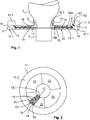
- FIG. 1 is shown purely schematically a device for cooling a film 1, which can be produced in a not explicitly shown film extrusion line.
- it is a blown film extrusion plant, which causes a discharge of the film 1 via a blowing head 3.
- the exemplary embodiments shown can likewise be applied to various extrusion systems, in particular to a flat film extrusion line, which likewise works with a blow head, from which the film emerges.
- a housing 11 of the cooling device according to the invention is provided in order to cool the film 1 emerging from the blow head 3.
- the cooling device substantially corresponds to the described cooling unit of the PCT / EP2011 / 072648 ,
- the film 1 is cooled by a cooling gas 2 at defined locations, wherein an actuating arrangement 10 ensures how high the volume flow of the cooling gas 2, which strikes the film 1, and how high the temperature of this cooling gas 1 is.
- a plurality of channels 12 are provided, each channel having an inlet opening 13 and an outlet opening 14 for the cooling gas 2.
- the actuating arrangement 10 has a lever system, wherein the lever system is designed in each channel 12 with a movable valve element 16.
- the actuator 15 At the valve element 16 according to FIG. 1 acts a movable actuator 15. In FIG. 1 the zero position of the actuator 15 is not shown. In the zero position, the actuator 15 is in the horizontal position, wherein the valve element 16 is located directly on the actuator 15.
- the actuator 15 is in direct contact with the valve member 16. If a movement of the actuator 15 from the zero position to the operating position shown, the valve member 16 pivots about its axis 18, whereby the cross section of the channel 12 is changed and thus the Volume flow of the cooling gas 2 is affected.
- the actuator 15 is a bimetallic element.
- the adjusting arrangement 10 has a heating element 17, which can bring about a defined introduction of a temperature, the actuator 15 from its zero position in an operating position.
- the heating element 17 acts as a drive for the movement of the actuator 15 to pivot the valve member 16 in the desired position.
- the drive for the actuator 15 is realized by an electric drive or by a pneumatic drive or by a hydraulic drive.
- the heating element 17 also has the function of influencing or varying the temperature of the cooling gas 2 flowing through the housing 11.
- valve element 16 has a free end 16.1, which faces the outlet opening 14.
- the actuator 15, however, has a free end 15.1, which faces the inlet opening 13. Since the free end 15.1 of the actuator 15 acts relatively centrally on the valve element 16, a good and effective adjustment of the valve element 16 can be achieved. The further the free end 15.1 acts on the underside 16b of the valve element 16 towards the axis 18, the higher an actuating action of the valve element 16 can be achieved.
- the upper side 16 a of the valve element 16 faces the flow of the cooling gas 2.
- the actuator 15 acts with its free end 15.1.
- the actuator 15 is remote from the flow of the cooling gas. 2
- the housing 11 has an inlet opening 11.1.
- the cooling gas 2 passes through a reservoir 11.2 in the channel 12, wherein at the same time depending on the requirements regarding.
- the thickness of the film 1, the actuator assembly 10 can vary the flow rate of the cooling gas 2 and the temperature of the cooling gas 2. This is done by a corresponding change in position of the valve element 16 and a corresponding heat input by the heating element 17 in the cooling gas. 2
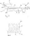
- FIG. 2 schematically a plan view of the cooling device according to the invention with the actuator assembly 10 is shown.
- the actuating arrangement has a plurality of valve elements 16 and a plurality of actuators are provided to the To move valve elements 16 accordingly in an operating position.
- the illustrated lever system of the actuator assembly 10 includes a plurality of lever units 20 that are configured of a plurality of movable valve members 16. According to FIG. 3 this is also referred to.
- the valve elements 16 are connected to each other via a web 21, which in FIG. 3 and FIG. 4 is shown.
- the web 21 and the valve elements 16 of each lever unit 20 form a monolithic component.
- this monolithic component is a metallic stamped part, in particular a sheet metal part.
- the monolithic component is according to FIG. 2 to FIG. 4 formed like a comb.
- an actuator 15 acts only on a valve element 16. If now the actuator 15 is pivoted, there is simultaneously a movement of the actuator 15 in contact valve element 16, which pivots about the axis 18. At the same time, the valve elements 16 connected to the common web 21 pivot, whereby each valve element 16 reaches its respective operating position within its channel. As a result, cross-sectional changes in each channel 12 can be achieved.
- a possible lever unit 20 is also in FIG. 4 shown.
- the adjusting arrangement 10 has a main body 30 with a bottom 31.
- the main body 30 forms a plurality of channels 12, in which the valve elements 16 are arranged to be movable.
- the lever unit 20 is inserted in a receptacle 33 of the main body 30, wherein the web 21 is reliably held in said receptacle 33. In addition, it is ensured that the lever unit 20 can be pivoted about the axis 18.
- the bottom 31 has a receptacle 32 in which the heating element 17 can be introduced.
- Each channel 12 is bounded by channel walls 19.
- a plurality of base bodies 30 can be arranged, which can be inserted in the housing 11.
- the housing may be composed of several sectors 22 contract, in each of which one or more base body 30 can be used. By way of example, however, only a portion of a sector 22 is shown, in which a base body 30 is positioned with the adjusting arrangement 10.
- the actual embodiment provides that the housing 11 is completely filled by one or more adjusting arrangements 10, in particular valve elements 16, actuators 15, etc.
- FIG. 2 is this Housing 11 ring-like formed by a plurality of actuators 15 and valve elements 16 are positioned, wherein the flow direction of the cooling gas 2 extends radially to the annular housing 11.
- the housing 11 is rod-shaped, in which a plurality of actuators 15 and valve elements 16 are arranged, which are arranged side by side.
- a plurality of actuators 15 and valve elements 16 are arranged, which are arranged side by side.
- This is on the PCT / EP2011 / 072648 Reference is made, which has such a linear arrangement of the valve elements in Figure 7.
- the use of basic bodies 30 is according to FIG. 3 conceivable.
Description
Die Erfindung betrifft eine Vorrichtung zum Kühlen einer Folie, die insbesondere in einer Folienextrusionsanlage erzeugbar ist, mit einem Gehäuse, das zumindest einen Kanal sowie zumindest eine Eintrittsöffnung und zumindest eine Austrittsöffnung aufweist, durch die ein Kühlgas strömbar ist, und einer Stellanordnung, mit der der durch die Austrittsöffnung ausströmbare Volumenstrom des Kühlgases und die Temperatur des durch die Austrittsöffnung auströmbaren Kühlgases einstellbar ist.The invention relates to a device for cooling a film, which can be produced in particular in a film extrusion plant, comprising a housing having at least one channel and at least one inlet opening and at least one outlet opening, through which a cooling gas can flow, and an actuating arrangement with which can be adjusted through the outlet opening flowable volume flow of the cooling gas and the temperature of the ausströmbaren through the outlet cooling gas.
In der
Aufgabe der vorliegenden Erfindung ist es, eine Vorrichtung zum Kühlen einer Folie bei der Folienherstellung derart weiterzubilden, dass zum Einen auf einfache Weise Folien mit einem möglichst geringen Foliendickenunterschied hergestellt werden und zum Anderen die Funktionalität und die Effizienz der dafür notwendigen Stellanordnung noch weiter verbessert und optimiert wird.Object of the present invention is to provide a device for cooling a film in the film production in such a way that on the one hand in a simple way films are produced with the smallest possible film thickness difference and on the other hand, the functionality and efficiency of the necessary adjustment arrangement even further improved and optimized becomes.
Die oben genannte Aufgabe wird durch sämtliche Merkmale des Patentanspruches 1 gelöst. In den abhängigen Ansprüchen sind vorteilhafte Weiterbildungen ausgeführt.The above object is solved by all features of claim 1. In the dependent claims advantageous developments are carried out.
Erfindungsgemäß ist vorgesehen, dass die Stellanordnung ein Hebelsystem umfasst, das ein bewegbares Stellglied und ein bewegbares Ventilelement aufweist, wobei das Stellglied derart auf das Ventilelement wirkt, dass eine Stellwirkung des Ventilelementes verstärkt ist. Eine Besonderheit der vorliegenden Erfindung ist, dass das zu verstellende Ventilelement über das Stellglied effektiver in die jeweilige Position gebracht werden kann. Zudem sorgt das Stellglied dafür, dass eine hohe Stellwirkung des den Volumenstrom des Kühlgases regulierenden Ventilelementes erzielt wird, in dem das Stellglied an einer definierten Stelle am Ventilelement angreift. Eine geringe Auslenkung des Stellgliedes hat erfindungsgemäß zur Folge, dass das Ventilelement einen größeren Stellweg bzw. eine größere Positionsveränderung erfährt, wodurch sich die erhöhte Stellwirkung realisieren lässt.According to the invention, it is provided that the actuating arrangement comprises a lever system which has a movable actuator and a movable valve element, wherein the actuator acts on the valve element such that an actuating action of the valve element is reinforced. A special feature of the present invention is that the valve element to be adjusted via the actuator can be brought into the respective position more effectively. In addition, the actuator ensures that a high actuating effect of the volume flow of the cooling gas regulating valve element is achieved, in which the actuator engages at a defined location on the valve element. A small deflection of the actuator according to the invention with the result that the valve element undergoes a greater travel or a larger change in position, whereby the increased actuating action can be realized.
Erfindungsgemäß umfasst die Erfindung, dass das Ventilelement der Strömung des Kühlgases zugewandt ist und das Stellglied der Strömung des Kühlgases abgewandt ist. Das Ventilelement bestimmt erfindungsgemäß den Querschnitt des Kanals, durch den das Kühlgas in Richtung Austrittsöffnung strömen kann.According to the invention, the invention comprises that the valve element faces the flow of the cooling gas and the actuator faces away from the flow of the cooling gas. The valve element according to the invention determines the cross section of the channel through which the cooling gas can flow in the direction of the outlet opening.
Über die Stellanordnung kann der Volumenstrom des Kühlgases und die Temperatur des Kühlgases gleichzeitig eingestellt werden, um eine Profildickenoptimierung der Folie realisieren zu können. Um die Dicke der Folie, insbesondere eines Folienschlauches regeln zu können, wird eine extrudierte Kunststoffschmelze, die z. B. aus einem Blaskopf einer Folienextrusionsanlage entweicht, unterschiedlich über die erfindungsgemäße Vorrichtung erwärmt und/oder gekühlt, wodurch das Dickenprofil der Folie einstellbar ist bzw. beeinflussbar ist. Hierbei wird die Wirkung ausgenutzt, dass bei der Bildung der Folie aus der Folienextrusionsanlage die wärmeren Bereich stärker und die kühleren Bereiche weniger stark ausgereckt werden. Das bedeutet, dass ein höher temperiertes Kühlgas ein dünneres Ausziehen der Folie bewirkt. Parallel umfasst die Erfindung den technischen Vorteil, dass neben der Einstellung der Temperatur des Kühlgases gleichzeitig der Volumenstrom des Kühlgases intelligent variiert werden kann, und zwar in Abhängigkeit von der Temperatur des Kühlgases. Das bedeutet, dass bei einem geringeren Volumenstrom des Kühlgases die Folie noch weiter ausgezogen bzw. verdünnt wird, wodurch eine Stellwirkung beider Parameter, d. h. Kühlgasvolumenstrom und Kühlgastemperatur um ein Vielfaches erhöht werden kann. Folglich ist die erfindungsgemäße Stellanordnung in der Lage, das Dickenprofil der Folie in kürzester Zeit einzustellen.About the actuator assembly, the flow rate of the cooling gas and the temperature of the cooling gas can be adjusted simultaneously to a profile thickness optimization of the film to be able to realize. In order to control the thickness of the film, in particular a film tube, an extruded plastic melt, the z. B. escapes from a blowing head of a film extrusion plant, heated and / or cooled differently over the device according to the invention, whereby the thickness profile of the film is adjustable or can be influenced. Here, the effect is exploited that in the formation of the film from the film extrusion line, the warmer area stronger and the cooler areas are less pronounced. This means that a higher temperature cooling gas causes a thinner extraction of the film. In parallel, the invention comprises the technical advantage that in addition to the adjustment of the temperature of the cooling gas at the same time the volume flow of the cooling gas can be intelligently varied, depending on the temperature of the cooling gas. This means that at a lower flow rate of the cooling gas, the film is further extended or diluted, whereby an adjustment of both parameters, ie cooling gas volume flow and cooling gas temperature can be increased by a multiple. Consequently, the adjusting arrangement according to the invention is able to adjust the thickness profile of the film in a very short time.
Ebenfalls ist es denkbar, dass die erfindungsgemäße Stellanordnung dafür sorgt, dass der Kühlgasvolumenstrom in Abhängigkeit von der Kühlgastemperatur oder umgekehrt gesteuert und/oder geregelt wird, dass bedeutet, dass bei einer Änderung der Temperatur des Kühlgases gleichzeitig und parallel der Volumenstrom des Kühlgases veränderbar ist. Um eine Verdünnung der Folie an einer definierten Stelle zu erzielen, kann beispielsweise die erfindungsgemäße Vorrichtung derart funktionieren, dass neben einer Erhöhung der Kühlgastemperatur gleichzeitig der Volumenstrom des Kühlgases bezogen auf den jeweiligen Abschnitt der Folie verringert wird.It is also conceivable that the adjusting arrangement according to the invention ensures that the cooling gas volume flow is controlled and / or regulated as a function of the cooling gas temperature or vice versa, which means that the volume flow of the cooling gas can be changed simultaneously and in parallel when the temperature of the cooling gas changes. In order to achieve a dilution of the film at a defined location, the device according to the invention may, for example, function in such a way that, in addition to an increase in the cooling gas temperature, the volume flow of the cooling gas is simultaneously reduced with respect to the respective section of the film.
Vorteilhafterweise ist vorgesehen, dass das Ventilelement den Querschnitt des Kanals bestimmt. Hierbei steht das Stellglied in Wirkverbindung zum Ventilelement, wobei über eine Auslenkung des Stellgliedes das Ventilelement entsprechend seine Position ändert, wodurch wirkungsvoll der Volumenstrom des Kühlgases einstellbar ist.Advantageously, it is provided that the valve element determines the cross section of the channel. In this case, the actuator is in operative connection with the valve element, wherein the valve element correspondingly changes its position via a deflection of the actuator, whereby the volume flow of the cooling gas is effectively adjustable.
Ferner umfasst die Erfindung eine Stellanordnung mit zumindest einem Heizelement, wodurch die Temperatur des Kühlgases einstellbar ist. Der Volumenstrom des Kühlgases sowie die Temperatur des Kühlgases können hiermit gleichzeitig gesteuert und/oder geregelt werden. Die Stellanordnung sorgt somit dafür, dass der Kühlgasvolumenstrom sowie die Kühlgastemperatur gleichzeitig nach definierten Vorgaben eingestellt werden. Das durch das Gehäuse sowie durch den Kanal strömende Kühlgas wird über das Heizelement entsprechend temperiert. Zusätzlich lässt sich über das Hebelsystem der Volumenstrom des Kühlgases entsprechend einstellen, sodass ein gezielter Volumenstrom mit einer definierten Temperatur das Gehäuse verlässt und auf einen definierten Bereich der Folie trifft, um die Dicke der Folie entsprechend einzustellen.Furthermore, the invention comprises an actuating arrangement with at least one heating element, whereby the temperature of the cooling gas is adjustable. The volume flow of the cooling gas and the temperature of the cooling gas can hereby simultaneously controlled and / or regulated become. The positioning arrangement thus ensures that the cooling gas volume flow and the cooling gas temperature are adjusted simultaneously according to defined specifications. The cooling gas flowing through the housing as well as through the channel is appropriately tempered via the heating element. In addition, the volume flow of the cooling gas can be correspondingly adjusted via the lever system so that a targeted volume flow with a defined temperature leaves the housing and strikes a defined area of the film in order to adjust the thickness of the film accordingly.
Vorteilhafterweise kann die Stellanordnung einen Antrieb aufweisen, der in Wirkverbindung zum Stellglied steht. Hierbei kann der Antrieb ein elektrischer Antrieb oder ein pneumatischer Antrieb oder ein hydraulischer Antrieb sein. Erfindungsgemäß ist das Heizelement der Antrieb für das Stellglied und/oder das Ventilelement.Advantageously, the actuator assembly may comprise a drive which is operatively connected to the actuator. Here, the drive can be an electric drive or a pneumatic drive or a hydraulic drive. According to the invention, the heating element is the drive for the actuator and / or the valve element.
In einer weiteren die Erfindung verbessernden Maßnahme kann über eine Veränderung der Position des Stellgliedes die Position des Ventilelementes veränderbar sein. Hierbei kann es von Vorteil sein, dass das Ventilelement innerhalb des Gehäuses schwenkbar um eine Achse gelagert ist. Vorteilhafterweise ist die Achse der Eintrittsöffnung zugewandt.In a further measure improving the invention, the position of the valve element can be changed by changing the position of the actuator. It may be advantageous that the valve element is mounted within the housing pivotable about an axis. Advantageously, the axis faces the inlet opening.
Erfindungsgemäß ist das Stellglied und/oder das Ventilelement ein Bimetallelement. Vorteilhafterweise ist das Stellglied ein verbiegbares Bimetallelement, durch das mit Änderung der Temperatur des Kühlgases zusätzlich der Volumenstrom des Kühlgases durch eine Verringerung oder eine Vergrößerung des Querschnittes des Kanals, durch den der Kühlgasvolumenstrom leitbar ist, veränderbar ist. Das Bimetallelement kann hierbei mit dem Heizelement derart gekoppelt sein, dass über die Änderung der Kühlgastemperatur der um das Bimetallelement (Stellglied) strömende Kühlgasvolumenstrom gleichzeitig dafür sorgt, dass das Stellglied sich entsprechend verbiegt und/oder einstellt, wodurch gleichzeitig das Ventilelement in seiner Position verändert wird. Hierdurch lässt sich der Volumenstrom des Kühlgases innerhalb des Kanals variieren.According to the invention, the actuator and / or the valve element is a bimetallic element. Advantageously, the actuator is a bendable bimetallic element, by changing the temperature of the cooling gas in addition, the volume flow of the cooling gas by a reduction or increase in the cross section of the channel through which the cooling gas flow is controllable, is variable. The bimetallic element may in this case be coupled to the heating element in such a way that via the change in the cooling gas temperature the cooling gas volume flow flowing around the bimetal element (actuator) simultaneously ensures that the actuator bends and / or adjusts accordingly, whereby the valve element is simultaneously changed in its position , As a result, the volume flow of the cooling gas can be varied within the channel.
Zudem ist es denkbar, dass der Querschnitt der Auslassöffnung durch eine Positionsänderung des Ventilelementes veränderbar ist, insbesondere in einer Nulllage des Ventilelementes die Auslassöffnung geöffnet ist und in einer möglichen Betriebslage des Ventilelementes der Querschnitt der Auslassöffnung bis zu 60% - 85% der Nulllage reduzierbar ist. Hierbei lässt sich über eine geringe Positionsänderung des Stellgliedes eine große Positionsänderung des Ventilelementes erreichen, wodurch unterschiedliche Betriebslagen des Ventilelementes realisierbar sind.In addition, it is conceivable that the cross section of the outlet opening is variable by a change in position of the valve element, in particular in a zero position of the valve element, the outlet opening is open and in a possible operating position of the valve element, the cross section of the outlet opening up to 60% - 85% of the zero position is reducible. This can be achieved by a small change in position of the actuator, a large change in position of the valve element, whereby different operating positions of the valve element can be realized.
In der Erfindung ist mit umfasst, dass das Hebelsystem zumindest eine Hebeleinheit aufweist, die eine Vielzahl an beweglichen Ventilelementen aufweist, die über einen Steg miteinander verbunden sind, wobei insbesondere der Steg und die Ventilelemente ein monolithisches Bauteil bilden. Die Ventilelemente sind jeweils in einem Kanal beweglich angeordnet, wobei das Gehäuse die einzelnen Kanäle mit dem Hebelsystem sowie der zumindest einen Hebeleinheit umfasst. Vorteilhafterweise kann die Anzahl der Stellglieder geringer sein als die Anzahl der Ventilelemente. Hierbei kann es ausreichen, dass ein oder eine geringe Anzahl an Stellgliedern an einem Ventilelement jeweils angreift. Über eine Bewegung des Stellgliedes erfolgt eine Auslenkung des mit dem jeweiligen Stellglied in Wirkverbindung stehenden Ventilelementes. Da sämtliche Ventilelemente über den gemeinsamen Steg verbunden sind, erfolgt gleichzeitig eine Mitbewegung der restlichen Ventilelemente in den jeweiligen Kanälen. Es können mehrere Hebelelemente innerhalb des Gehäuses der erfindungsgemäßen Vorrichtung vorgesehen sein.In the invention, it is included in that the lever system has at least one lever unit which has a plurality of movable valve elements, which are connected to one another via a web, wherein in particular the web and the valve elements form a monolithic component. The valve elements are each arranged to be movable in a channel, the housing comprising the individual channels with the lever system and the at least one lever unit. Advantageously, the number of actuators may be less than the number of valve elements. It may be sufficient that one or a small number of actuators each acts on a valve element. By means of a movement of the actuator, a deflection of the valve element operatively connected to the respective actuator takes place. Since all valve elements are connected via the common web, there is also a co-movement of the remaining valve elements in the respective channels. There may be provided a plurality of lever elements within the housing of the device according to the invention.
In einer möglichen Ausführungsform der Erfindung kann das monolithische Bauteil, das sich aus dem Steg sowie den damit verbundenen Ventilelementen zusammensetzt, ein metallisches Stanzteil sein. Hierbei kann das monolithische Bauteil eine kammartige Geometrie aufweisen.In one possible embodiment of the invention, the monolithic component, which is composed of the web and the associated valve elements, be a metallic stamped part. Here, the monolithic component may have a comb-like geometry.
Zudem ist es denkbar, dass die Stellanordnung innerhalb des Gehäuses zumindest einen Grundkörper aufweist, der mit einer Vielzahl an Kanälen für das Kühlgas ausgebildet ist, wobei in jedem Kanal ein Ventilelement angeordnet ist. Hierbei kann die Erfindung mit umfassen, dass der Grundkörper einen Boden aufweist, der das Heizelement aufnimmt und/oder auf dem das Ventilelement und/oder das Stellglied und/oder die Hebeleinheit aufliegt.In addition, it is conceivable that the actuating arrangement has at least one main body within the housing, which is formed with a plurality of channels for the cooling gas, wherein a valve element is arranged in each channel. Here, the invention may include that the base body has a bottom which receives the heating element and / or on which the valve element and / or the actuator and / or the lever unit rests.
In einer weiteren die Erfindung verbessernden Maßnahme kann das Gehäuse ringartig ausgebildet sein, in dem eine Vielzahl an Stellgliedern und Ventilelementen angeordnet sind, wobei die Strömungsrichtung des Kühlgases radial zum ringartigen Gehäuse verläuft oder dass das Gehäuse stabförmig ausgebildet ist, in dem eine Vielzahl an Stellgliedern und Ventilelementen angeordnet sind, die nebeneinander angeordnet sind. Die Anzahl der Ventilelemente kann größer sein als die Anzahl der Stellglieder.In a further measure improving the invention, the housing may be formed like a ring, in which a plurality of actuators and valve elements are arranged, wherein the flow direction of the cooling gas extends radially to the annular housing or that the housing is rod-shaped, in which a plurality of actuators and valve elements are arranged, which are arranged side by side. The number of valve elements may be greater than the number of actuators.
Die Stellwirkung der Stellanordnung kann dadurch verstärkt werden, dass das Ventilelement ein freies Ende aufweist, das der Austrittsöffnung zugewandt ist und das Stellglied ein freies Ende aufweist, dass der Eintrittsöffnung zugewandt ist, wobei insbesondere der Abstand zwischen dem freien Ende des Stellgliedes und der Achse des Ventilelementes geringer ist als der Abstand zwischen dem freien Ende des Ventilelementes und dem freien Ende des Stellgliedes. Somit kann es ausreichen, dass über eine geringe Verstellung oder Positionsänderung des freien Endes des Stellgliedes, welches direkt auf das Ventilelement wirkt, eine große Positionsänderung des freien Endes des Ventilelementes bewirkt wird, wodurch eine große Veränderung des Querschnittes des Kanals erzielbar ist, durch den das Kühlgas strömt und an einer definierten Stelle auf die Folie trifft.The actuating action of the actuating arrangement can be reinforced by the fact that the valve element has a free end which faces the outlet opening and the actuator has a free end that faces the inlet opening, wherein in particular the distance between the free end of the actuator and the axis of the Valve element is less than the distance between the free end of the valve element and the free end of the actuator. Thus, it may be sufficient that a small change or change in position of the free end of the actuator, which acts directly on the valve element, a large change in position of the free end of the valve element is effected, whereby a large change in the cross section of the channel can be achieved by the Cooling gas flows and hits the film at a defined location.
In einer möglichen Ausgestaltung der Erfindung weist die Stellanordnung eine Vielzahl an Heizelementen auf, wobei jedes Heizelement einem Kanal zugeordnet ist. Das Heizelement kann beispielsweise als Heizpatrone ausgebildet sein. Über das Hebelsystem mit der erhöhten Stellwirkung hat sich gezeigt, dass weniger Heizenergie für das Heizelement bzw. für die Heizelemente notwendig ist, um die gleiche Stellwirkung zu erzielen.In one possible embodiment of the invention, the actuating arrangement has a plurality of heating elements, each heating element being associated with a channel. The heating element may be formed, for example, as a heating cartridge. The lever system with the increased actuating action has shown that less heating energy is required for the heating element or for the heating elements in order to achieve the same setting effect.
Weitere Vorteile, Merkmale und Einzelheiten ergeben sich aus der nachfolgenden Beschreibung, in der unter Bezugnahme auf die Zeichnungen mehrere Ausführungsbeispiele der Erfindung im Einzelnen beschrieben sind. Dabei können die in den Ansprüchen und in der Beschreibung erwähnten Merkmale jeweils einzeln für sich oder in beliebiger Kombination erfindungswesentlich sein. Es zeigen:
- Fig. 1
- eine schematische Schnittansicht auf eine erfindungsgemäße Vorrichtung zum Kühlen einer Folie mit einer Stellanordnung, die ein Hebelsystem umfasst,
- Fig. 2
- eine mögliche Draufsicht eines Ausführungsbeispieles auf eine Stellanordnung, die gemäß
Figur 1 einsetzbar ist,
- Fig.3
- eine weitere Darstellung eines Ausführungsbeispieles einer möglichen Stellanordnung und
- Fig. 4
- eine schematische Draufsicht auf eine Hebeleinheit, die in der Stellanordnung angeordnet ist.
- Fig. 1
- a schematic sectional view of an inventive device for cooling a film with an actuator assembly comprising a lever system,
- Fig. 2
- a possible top view of an embodiment of an actuating arrangement according to
FIG. 1 can be used,
- Figure 3
- a further illustration of an embodiment of a possible actuator assembly and
- Fig. 4
- a schematic plan view of a lever unit which is arranged in the actuating arrangement.
In
Beabstandet zum Blaskopf 3 ist ein Gehäuse 11 der erfindungsgemäßen Kühlvorrichtung vorgesehen, um die aus dem Blaskopf 3 austretende Folie 1 zu kühlen. Die Kühlvorrichtung entspricht im Wesentlichen der beschriebenen Kühleinheit aus der
Hierbei wird die Folie 1 durch ein Kühlgas 2 an definierten Stellen gekühlt, wobei eine Stellanordnung 10 dafür sorgt, wie hoch der Volumenstrom des Kühlgases 2 ist, der auf die Folie 1 trifft, und wie hoch die Temperatur dieses Kühlgases 1 ist. Innerhalb des Gehäuses 11 sind eine Vielzahl an Kanälen 12 vorgesehen, wobei jeder Kanal eine Eintrittsöffnung 13 und eine Austrittsöffnung 14 für das Kühlgas 2 aufweist. Die Stellanordnung 10 weist ein Hebelsystem auf, wobei das Hebelsystem in jedem Kanal 12 mit einem bewegbaren Ventilelement 16 ausgeführt ist. Am Ventilelement 16 gemäß
Im vorliegenden Ausführungsbeispiel ist das Stellglied 15 ein Bimetallelement. Zudem weist die Stellanordnung 10 ein Heizelement 17 auf, welches über eine definierte Einbringung einer Temperatur das Stellglied 15 aus seiner Nulllage in eine Betriebslage bringen kann. Das Heizelement 17 wirkt als Antrieb zur Bewegung des Stellgliedes 15, um das Ventilelement 16 in die gewünschte Position zu verschwenken. Alternativ ist es denkbar, dass der Antrieb für das Stellglied 15 durch einen elektrischen Antrieb oder durch einen pneumatischen Antrieb oder durch einen hydraulischen Antrieb verwirklicht wird.In the present embodiment, the
Das Heizelement 17 hat zudem die Funktion die Temperatur des Kühlgases 2, das durch das Gehäuse 11 strömt, zu beeinflussen bzw. zu variieren.The
Wie
Die Oberseite 16a des Ventilelementes 16 ist der Strömung des Kühlgases 2 zugewandt. An der Unterseite 16b des Ventilelementes 16 wirkt hingegen das Stellglied 15 mit seinem freien Ende 15.1. Somit befindet sich das Stellglied 15 abgewandt zur Strömung des Kühlgases 2.The
Damit das Kühlgas 2 in das Gehäuse 11 einströmen kann, weist das Gehäuse 11 eine Einlassöffnung 11.1 auf. Das Kühlgas 2 gelangt über einen Vorratsraum 11.2 in den Kanal 12, wobei gleichzeitig je nach Anforderungen bzgl. der Dicke der Folie 1 die Stellanordnung 10 den Volumenstrom des Kühlgases 2 und die Temperatur des Kühlgases 2 variieren kann. Dieses erfolgt durch eine entsprechende Positionsveränderung des Ventilelementes 16 und einer entsprechenden Wärmeeinbringung durch das Heizelement 17 in das Kühlgas 2.So that the cooling
In
Zudem zeigen
In
- 11
- Foliefoil
- 22
- Kühlgascooling gas
- 33
- Blaskopfblow head
- 1010
- StellanordnungStella order
- 1111
- Gehäusecasing
- 11.111.1
- Einlassöffnunginlet port
- 11.211.2
- Vorratsraumpantry
- 1212
- Kanalchannel
- 1313
- Eintrittsöffnunginlet opening
- 1414
- Austrittsöffnungoutlet opening
- 1515
- Stellgliedactuator
- 15.115.1
- freies Endefree end
- 1616
- Ventilelementvalve element
- 16a16a
- Oberseitetop
- 16b16b
- Unterseitebottom
- 16.116.1
- freies Endefree end
- 1717
- Heizelementheating element
- 1818
- Achseaxis
- 1919
- Kanalwandungchannel wall
- 2020
- Hebeleinheitlever unit
- 2121
- Stegweb
- 2222
- Sektorsector
- 3030
- Grundkörperbody
- 3131
- Bodenground
- 3232
- Aufnahme für 17Recording for 17
- 3333
- Aufnahme für 20Recording for 20
Claims (15)
- Apparatus for cooling a film (1), which may be produced in particular in a film extrusion plant, with- a housing (11) comprising at least one channel (12), at least one inlet opening (13) and at least one outlet opening (14) through which a cooling gas (2) may flow,- an actuating arrangement (10), by means of which the volumetric flow of the cooling gas (2) which may flow out through the outlet opening (14), and the temperature of the cooling gas (2) which may flow out through the outlet opening (14), may be adjusted,
characterized in that
the actuating arrangement (10) comprises a lever system which has a movable actuator (15) and a movable valve element (16), wherein the actuator (15) acts on the valve element (16) in such a way as to amplify the actuating action of the valve element (16)
the actuating arrangement (10) has at least one heating element (17), wherein the temperature of the cooling gas (2) is adjustable, and wherein the heating element (17) is the drive for the actuator and/or the valve element (16), wherein the actuator (15) and/or the valve element (16) are/is (a) bimetallic element(s). - Apparatus according to claim 1,
characterized in that
the valve element (16) faces the flow of the cooling gas (2) while the actuator (15) faces away from the flow of the cooling gas (2). - Apparatus according to claim 1 or 2,
characterized in that
the actuator (15) is in operative connection with the valve element (16). - Device according to one of the preceding claims,
characterized in that
the valve element (16) determines the cross-section of the channel (12). - Device according to one of the preceding claims,
characterized in that
the actuating arrangement (10) has a drive which is in operative connection with the actuator (15). - Device according to one of the preceding claims,
characterized in that
the position of the valve element (16) may be changed by changing the position of the actuator (15). - Device according to one of the preceding claims,
characterized in that
the valve element (16) is mounted to pivot about an axis (18) within the housing (11), in particular wherein the axis (18) faces the inlet opening (13). - Device according to one of the preceding claims,
characterized in that
the actuator (15) contacts the valve element (16) on its side (16b) facing away from the flow of the cooling gas (2). - Device according to one of the preceding claims,
characterized in that
that the cross-section of the outlet opening (14) may be changed by a change in position of the valve element (16), in particular to a zero position of the valve element (16) wherein the outlet opening (14) is open, and to a possible operating position of the valve element (16) wherein the cross-section of the outlet opening (14) may be reduced up to 60% - 85% of the zero position. - Device according to one of the preceding claims,
characterized in that
the lever system has at least one lever unit (20) which has a plurality of movable valve elements (16) which are connected to one another via a web (21), wherein, in particular, the web (21) and the valve elements (16) form a monolithic component. - Device according to 10,
characterized in that
the monolithic component is a metallic stamped part. - Device according to one of the preceding claims,
characterized in that
the actuating arrangement (10) has at least one main body (30) within the housing (11), which is formed by a plurality of channels (12) for the cooling gas (2), wherein a valve element is arranged (16) in each channel (12), and wherein, in particular, the base body (30) comprises a bottom (31) which receives the heating element (17) and/or upon which the valve element (16) and/or the actuator (15) and/or the lever unit (20) rest(s). - Device according to one of the preceding claims,
characterized in that
the housing (11) is of an annular design, in which a plurality of actuators (15) and valve elements (16) are arranged, wherein the flow direction of the cooling gas (2) extends radially to the annular housing (11), or wherein the housing (11) is rod-shaped, in which a plurality of actuators (15) and valve elements (16) are arranged next to one another. - Device according to one of the preceding claims,
characterized in that
the actuating arrangement (10) simultaneously controls and/or regulates the volume flow of the cooling gas (2) as a function of the temperature of the cooling gas (2) or vice versa. - Device according to one of the preceding claims,
characterized in that
the valve element (16) has a free end (16.1) which faces the outlet opening (14) while the actuator (15) has a free end (15.1) which faces the inlet opening (13), wherein, in particular, the distance between the free end (15.1) of the actuator (15) and the axis (18) of the valve element (16) is less than the distance between the free end (16.1) of the valve element (16) and the free end (15.1) of the actuator (15).
Applications Claiming Priority (3)
| Application Number | Priority Date | Filing Date | Title |
|---|---|---|---|
| US201261657631P | 2012-06-08 | 2012-06-08 | |
| DE102012104963A DE102012104963A1 (en) | 2012-06-08 | 2012-06-08 | Device for cooling a film with a lever system |
| PCT/EP2013/061298 WO2013182493A1 (en) | 2012-06-08 | 2013-05-31 | Device for cooling a film, comprising a lever system |
Publications (2)
| Publication Number | Publication Date |
|---|---|
| EP2858804A1 EP2858804A1 (en) | 2015-04-15 |
| EP2858804B1 true EP2858804B1 (en) | 2018-02-14 |
Family
ID=49625814
Family Applications (1)
| Application Number | Title | Priority Date | Filing Date |
|---|---|---|---|
| EP13726775.3A Active EP2858804B1 (en) | 2012-06-08 | 2013-05-31 | Device for cooling a film, comprising a lever system |
Country Status (7)
| Country | Link |
|---|---|
| US (1) | US9810488B2 (en) |
| EP (1) | EP2858804B1 (en) |
| CN (1) | CN104364065B (en) |
| CA (1) | CA2875438A1 (en) |
| DE (1) | DE102012104963A1 (en) |
| IN (1) | IN2014DN10511A (en) |
| WO (1) | WO2013182493A1 (en) |
Families Citing this family (8)
| Publication number | Priority date | Publication date | Assignee | Title |
|---|---|---|---|---|
| US10357914B2 (en) * | 2016-01-15 | 2019-07-23 | Addex, Inc. | High performance cooling element |
| EP3455048B1 (en) * | 2016-05-09 | 2023-10-04 | Windmöller & Hölscher KG | Blown-film system for producing a blown film |
| US10473226B2 (en) | 2017-06-12 | 2019-11-12 | Hamilton Sundstrand Corporation | Heat exchanger valves |
| CN108189290B (en) * | 2018-01-26 | 2020-07-10 | 镇江双晟塑业有限公司 | PVC membrane processing cooling arrangement |
| DE102018124662A1 (en) * | 2018-10-05 | 2020-04-09 | Vermes Microdispensing GmbH | Dosing system with cooling device |
| CN110065225B (en) * | 2019-05-31 | 2021-03-16 | 重庆瑞霆塑胶有限公司 | Plastic film blowing equipment |
| US11618200B2 (en) * | 2020-03-17 | 2023-04-04 | Michael P. Bucko | External cooling air ring for blown-film extrusion |
| US11826941B1 (en) | 2022-06-28 | 2023-11-28 | Daniel R. Joseph | Air ring for blown-film extrusion apparatus |
Family Cites Families (15)
| Publication number | Priority date | Publication date | Assignee | Title |
|---|---|---|---|---|
| JPS5798930A (en) * | 1980-12-10 | 1982-06-19 | Matsushita Electric Works Ltd | Temperature switch |
| IL90625A0 (en) | 1989-06-15 | 1990-01-18 | Israel Rom | Apparatus for the production of a tubular-film from thermoplastic material |
| DK0478641T3 (en) * | 1989-06-21 | 1993-10-18 | Stefan Konermann | Method for controlling the thickness profile of a blow film and apparatus for carrying out the method |
| DE9108417U1 (en) | 1991-07-08 | 1991-08-29 | Konermann, Stefan, 4540 Lengerich, De | |
| DE4207439B4 (en) * | 1991-12-12 | 2004-05-06 | Windmöller & Hölscher Kg | Foil blowing head for the production of tubular foils from thermoplastic |
| US5804221A (en) * | 1996-09-05 | 1998-09-08 | Macro Engineering & Technology Inc. | Air ring for cooling blown plastic film |
| CN1218739A (en) * | 1997-11-28 | 1999-06-09 | 马科工程及技术公司 | Air ring for cooling blown plastic film |
| EP1004424A1 (en) | 1998-09-04 | 2000-05-31 | Macro Engineering & Technology Inc. | Air ring for cooling blown plastic film |
| JP3413167B2 (en) * | 2000-09-08 | 2003-06-03 | 古河精密金属工業株式会社 | Manufacturing method of small breaker |
| US7654808B2 (en) * | 2004-10-12 | 2010-02-02 | Macro Engineering and Technology, Inc. | Air ring with circumferentially adjustable air flow |
| CN101035667B (en) | 2004-10-12 | 2011-12-28 | 马科工程及技术公司 | Air ring with circumferentially adjustable air flow |
| CA2629990C (en) * | 2007-04-17 | 2011-07-19 | Kdesign Gmbh | A method of and device for cooling blown film during the production of blown film |
| ATE452016T1 (en) | 2007-10-22 | 2010-01-15 | Kdesign Gmbh | DEVICE HAVING A CONTROLLABLE MAIN COOLING GAS RING WITH RECTIFIER UNIT AND AN ADDITIONAL COOLING GAS RING |
| JP5402744B2 (en) | 2010-03-17 | 2014-01-29 | パナソニック株式会社 | Thermostat and seat heater provided with the same |
| CN103459122B (en) | 2010-12-14 | 2016-08-31 | 韦德穆勒&霍斯彻特两合公司 | For manufacturing and cool down device and the equipment of thin film |
-
2012
- 2012-06-08 DE DE102012104963A patent/DE102012104963A1/en not_active Withdrawn
-
2013
- 2013-05-31 WO PCT/EP2013/061298 patent/WO2013182493A1/en active Application Filing
- 2013-05-31 CN CN201380029673.3A patent/CN104364065B/en not_active Expired - Fee Related
- 2013-05-31 US US14/406,250 patent/US9810488B2/en active Active
- 2013-05-31 CA CA2875438A patent/CA2875438A1/en not_active Abandoned
- 2013-05-31 IN IN10511DEN2014 patent/IN2014DN10511A/en unknown
- 2013-05-31 EP EP13726775.3A patent/EP2858804B1/en active Active
Also Published As
| Publication number | Publication date |
|---|---|
| EP2858804A1 (en) | 2015-04-15 |
| CA2875438A1 (en) | 2013-12-12 |
| DE102012104963A1 (en) | 2013-12-12 |
| CN104364065B (en) | 2016-09-14 |
| WO2013182493A1 (en) | 2013-12-12 |
| US20150153117A1 (en) | 2015-06-04 |
| CN104364065A (en) | 2015-02-18 |
| IN2014DN10511A (en) | 2015-08-21 |
| US9810488B2 (en) | 2017-11-07 |
Similar Documents
| Publication | Publication Date | Title |
|---|---|---|
| EP2858804B1 (en) | Device for cooling a film, comprising a lever system | |
| EP2651620B1 (en) | Apparatus and plant for manufacturing and cooling a foil | |
| EP0179304B1 (en) | Radiator shutter | |
| EP2203668B1 (en) | Control valve | |
| EP1859329B1 (en) | Flow regulator | |
| EP3031530B1 (en) | Duct cleaning system with at least one nozzle | |
| DE3918218A1 (en) | AIR OUTLET | |
| EP2172357A2 (en) | Device for controlling the air throughput of an air hole | |
| WO2015188284A2 (en) | Valve for use in the feed pipe or return pipe of a heating or cooling water circuit | |
| DE102011006647B4 (en) | Mechanical device for realizing an opening with variable opening widths | |
| EP2993310A1 (en) | Method for extracting bleed air and aircraft engine with at least one device for the extraction of bleed air | |
| DE202007005860U1 (en) | cooler system | |
| EP2160086B1 (en) | Cooling device for cooling an electronic control device and an electronic control device | |
| DE2314978C2 (en) | Slotted gallery cylinder liner shut-off and regulating device for Cowper armatures | |
| EP2669573A1 (en) | Throttle device | |
| EP2684719B1 (en) | Fragrance device | |
| EP0808992A2 (en) | Rotary slide valve for the control of steam flow to a steam turbine | |
| EP3150936B1 (en) | Air outlet and method for operating the air outlet | |
| EP1738941A1 (en) | Vehicle air-conditioner | |
| EP0716366A2 (en) | Flow control device, in particular a valve | |
| EP3453545A1 (en) | Air vent for vehicle interiors | |
| DE102014105035B4 (en) | Motor vehicle air conditioning system with several control flaps | |
| DE3636108C2 (en) | ||
| EP3456984B1 (en) | Valve for controlling a fluid flow | |
| DE202020000872U1 (en) | Thermal regulating valve |
Legal Events
| Date | Code | Title | Description |
|---|---|---|---|
| PUAI | Public reference made under article 153(3) epc to a published international application that has entered the european phase |
Free format text: ORIGINAL CODE: 0009012 |
|
| 17P | Request for examination filed |
Effective date: 20150108 |
|
| AK | Designated contracting states |
Kind code of ref document: A1 Designated state(s): AL AT BE BG CH CY CZ DE DK EE ES FI FR GB GR HR HU IE IS IT LI LT LU LV MC MK MT NL NO PL PT RO RS SE SI SK SM TR |
|
| AX | Request for extension of the european patent |
Extension state: BA ME |
|
| DAX | Request for extension of the european patent (deleted) | ||
| 17Q | First examination report despatched |
Effective date: 20151125 |
|
| GRAP | Despatch of communication of intention to grant a patent |
Free format text: ORIGINAL CODE: EPIDOSNIGR1 |
|
| STAA | Information on the status of an ep patent application or granted ep patent |
Free format text: STATUS: GRANT OF PATENT IS INTENDED |
|
| INTG | Intention to grant announced |
Effective date: 20170614 |
|
| GRAS | Grant fee paid |
Free format text: ORIGINAL CODE: EPIDOSNIGR3 |
|
| GRAL | Information related to payment of fee for publishing/printing deleted |
Free format text: ORIGINAL CODE: EPIDOSDIGR3 |
|
| GRAS | Grant fee paid |
Free format text: ORIGINAL CODE: EPIDOSNIGR3 |
|
| GRAA | (expected) grant |
Free format text: ORIGINAL CODE: 0009210 |
|
| STAA | Information on the status of an ep patent application or granted ep patent |
Free format text: STATUS: THE PATENT HAS BEEN GRANTED |
|
| AK | Designated contracting states |
Kind code of ref document: B1 Designated state(s): AL AT BE BG CH CY CZ DE DK EE ES FI FR GB GR HR HU IE IS IT LI LT LU LV MC MK MT NL NO PL PT RO RS SE SI SK SM TR |
|
| REG | Reference to a national code |
Ref country code: GB Ref legal event code: FG4D Free format text: NOT ENGLISH |
|
| REG | Reference to a national code |
Ref country code: CH Ref legal event code: EP |
|
| REG | Reference to a national code |
Ref country code: IE Ref legal event code: FG4D Free format text: LANGUAGE OF EP DOCUMENT: GERMAN |
|
| REG | Reference to a national code |
Ref country code: DE Ref legal event code: R096 Ref document number: 502013009410 Country of ref document: DE Ref country code: AT Ref legal event code: REF Ref document number: 969585 Country of ref document: AT Kind code of ref document: T Effective date: 20180315 |
|
| REG | Reference to a national code |
Ref country code: NL Ref legal event code: MP Effective date: 20180214 |
|
| PG25 | Lapsed in a contracting state [announced via postgrant information from national office to epo] |
Ref country code: HR Free format text: LAPSE BECAUSE OF FAILURE TO SUBMIT A TRANSLATION OF THE DESCRIPTION OR TO PAY THE FEE WITHIN THE PRESCRIBED TIME-LIMIT Effective date: 20180214 Ref country code: CY Free format text: LAPSE BECAUSE OF FAILURE TO SUBMIT A TRANSLATION OF THE DESCRIPTION OR TO PAY THE FEE WITHIN THE PRESCRIBED TIME-LIMIT Effective date: 20180214 Ref country code: LT Free format text: LAPSE BECAUSE OF FAILURE TO SUBMIT A TRANSLATION OF THE DESCRIPTION OR TO PAY THE FEE WITHIN THE PRESCRIBED TIME-LIMIT Effective date: 20180214 Ref country code: ES Free format text: LAPSE BECAUSE OF FAILURE TO SUBMIT A TRANSLATION OF THE DESCRIPTION OR TO PAY THE FEE WITHIN THE PRESCRIBED TIME-LIMIT Effective date: 20180214 Ref country code: NL Free format text: LAPSE BECAUSE OF FAILURE TO SUBMIT A TRANSLATION OF THE DESCRIPTION OR TO PAY THE FEE WITHIN THE PRESCRIBED TIME-LIMIT Effective date: 20180214 Ref country code: FI Free format text: LAPSE BECAUSE OF FAILURE TO SUBMIT A TRANSLATION OF THE DESCRIPTION OR TO PAY THE FEE WITHIN THE PRESCRIBED TIME-LIMIT Effective date: 20180214 Ref country code: NO Free format text: LAPSE BECAUSE OF FAILURE TO SUBMIT A TRANSLATION OF THE DESCRIPTION OR TO PAY THE FEE WITHIN THE PRESCRIBED TIME-LIMIT Effective date: 20180514 |
|
| PG25 | Lapsed in a contracting state [announced via postgrant information from national office to epo] |
Ref country code: BG Free format text: LAPSE BECAUSE OF FAILURE TO SUBMIT A TRANSLATION OF THE DESCRIPTION OR TO PAY THE FEE WITHIN THE PRESCRIBED TIME-LIMIT Effective date: 20180514 Ref country code: GR Free format text: LAPSE BECAUSE OF FAILURE TO SUBMIT A TRANSLATION OF THE DESCRIPTION OR TO PAY THE FEE WITHIN THE PRESCRIBED TIME-LIMIT Effective date: 20180515 Ref country code: RS Free format text: LAPSE BECAUSE OF FAILURE TO SUBMIT A TRANSLATION OF THE DESCRIPTION OR TO PAY THE FEE WITHIN THE PRESCRIBED TIME-LIMIT Effective date: 20180214 Ref country code: SE Free format text: LAPSE BECAUSE OF FAILURE TO SUBMIT A TRANSLATION OF THE DESCRIPTION OR TO PAY THE FEE WITHIN THE PRESCRIBED TIME-LIMIT Effective date: 20180214 Ref country code: LV Free format text: LAPSE BECAUSE OF FAILURE TO SUBMIT A TRANSLATION OF THE DESCRIPTION OR TO PAY THE FEE WITHIN THE PRESCRIBED TIME-LIMIT Effective date: 20180214 |
|
| PG25 | Lapsed in a contracting state [announced via postgrant information from national office to epo] |
Ref country code: MT Free format text: LAPSE BECAUSE OF FAILURE TO SUBMIT A TRANSLATION OF THE DESCRIPTION OR TO PAY THE FEE WITHIN THE PRESCRIBED TIME-LIMIT Effective date: 20180214 |
|
| PG25 | Lapsed in a contracting state [announced via postgrant information from national office to epo] |
Ref country code: AL Free format text: LAPSE BECAUSE OF FAILURE TO SUBMIT A TRANSLATION OF THE DESCRIPTION OR TO PAY THE FEE WITHIN THE PRESCRIBED TIME-LIMIT Effective date: 20180214 Ref country code: RO Free format text: LAPSE BECAUSE OF FAILURE TO SUBMIT A TRANSLATION OF THE DESCRIPTION OR TO PAY THE FEE WITHIN THE PRESCRIBED TIME-LIMIT Effective date: 20180214 Ref country code: PL Free format text: LAPSE BECAUSE OF FAILURE TO SUBMIT A TRANSLATION OF THE DESCRIPTION OR TO PAY THE FEE WITHIN THE PRESCRIBED TIME-LIMIT Effective date: 20180214 Ref country code: EE Free format text: LAPSE BECAUSE OF FAILURE TO SUBMIT A TRANSLATION OF THE DESCRIPTION OR TO PAY THE FEE WITHIN THE PRESCRIBED TIME-LIMIT Effective date: 20180214 |
|
| REG | Reference to a national code |
Ref country code: DE Ref legal event code: R097 Ref document number: 502013009410 Country of ref document: DE |
|
| REG | Reference to a national code |
Ref country code: DE Ref legal event code: R079 Ref document number: 502013009410 Country of ref document: DE Free format text: PREVIOUS MAIN CLASS: B29C0047880000 Ipc: B29C0048880000 |
|
| PG25 | Lapsed in a contracting state [announced via postgrant information from national office to epo] |
Ref country code: SM Free format text: LAPSE BECAUSE OF FAILURE TO SUBMIT A TRANSLATION OF THE DESCRIPTION OR TO PAY THE FEE WITHIN THE PRESCRIBED TIME-LIMIT Effective date: 20180214 Ref country code: DK Free format text: LAPSE BECAUSE OF FAILURE TO SUBMIT A TRANSLATION OF THE DESCRIPTION OR TO PAY THE FEE WITHIN THE PRESCRIBED TIME-LIMIT Effective date: 20180214 Ref country code: CZ Free format text: LAPSE BECAUSE OF FAILURE TO SUBMIT A TRANSLATION OF THE DESCRIPTION OR TO PAY THE FEE WITHIN THE PRESCRIBED TIME-LIMIT Effective date: 20180214 Ref country code: SK Free format text: LAPSE BECAUSE OF FAILURE TO SUBMIT A TRANSLATION OF THE DESCRIPTION OR TO PAY THE FEE WITHIN THE PRESCRIBED TIME-LIMIT Effective date: 20180214 |
|
| REG | Reference to a national code |
Ref country code: CH Ref legal event code: PL |
|
| PLBE | No opposition filed within time limit |
Free format text: ORIGINAL CODE: 0009261 |
|
| STAA | Information on the status of an ep patent application or granted ep patent |
Free format text: STATUS: NO OPPOSITION FILED WITHIN TIME LIMIT |
|
| 26N | No opposition filed |
Effective date: 20181115 |
|
| GBPC | Gb: european patent ceased through non-payment of renewal fee |
Effective date: 20180531 |
|
| REG | Reference to a national code |
Ref country code: BE Ref legal event code: MM Effective date: 20180531 |
|
| PG25 | Lapsed in a contracting state [announced via postgrant information from national office to epo] |
Ref country code: MC Free format text: LAPSE BECAUSE OF FAILURE TO SUBMIT A TRANSLATION OF THE DESCRIPTION OR TO PAY THE FEE WITHIN THE PRESCRIBED TIME-LIMIT Effective date: 20180214 |
|
| PG25 | Lapsed in a contracting state [announced via postgrant information from national office to epo] |
Ref country code: SI Free format text: LAPSE BECAUSE OF FAILURE TO SUBMIT A TRANSLATION OF THE DESCRIPTION OR TO PAY THE FEE WITHIN THE PRESCRIBED TIME-LIMIT Effective date: 20180214 Ref country code: LI Free format text: LAPSE BECAUSE OF NON-PAYMENT OF DUE FEES Effective date: 20180531 Ref country code: CH Free format text: LAPSE BECAUSE OF NON-PAYMENT OF DUE FEES Effective date: 20180531 |
|
| REG | Reference to a national code |
Ref country code: IE Ref legal event code: MM4A |
|
| PG25 | Lapsed in a contracting state [announced via postgrant information from national office to epo] |
Ref country code: LU Free format text: LAPSE BECAUSE OF NON-PAYMENT OF DUE FEES Effective date: 20180531 |
|
| PG25 | Lapsed in a contracting state [announced via postgrant information from national office to epo] |
Ref country code: IE Free format text: LAPSE BECAUSE OF NON-PAYMENT OF DUE FEES Effective date: 20180531 Ref country code: FR Free format text: LAPSE BECAUSE OF NON-PAYMENT OF DUE FEES Effective date: 20180531 Ref country code: GB Free format text: LAPSE BECAUSE OF NON-PAYMENT OF DUE FEES Effective date: 20180531 |
|
| PG25 | Lapsed in a contracting state [announced via postgrant information from national office to epo] |
Ref country code: BE Free format text: LAPSE BECAUSE OF NON-PAYMENT OF DUE FEES Effective date: 20180531 |
|
| REG | Reference to a national code |
Ref country code: AT Ref legal event code: MM01 Ref document number: 969585 Country of ref document: AT Kind code of ref document: T Effective date: 20180531 |
|
| PG25 | Lapsed in a contracting state [announced via postgrant information from national office to epo] |
Ref country code: AT Free format text: LAPSE BECAUSE OF NON-PAYMENT OF DUE FEES Effective date: 20180531 |
|
| PG25 | Lapsed in a contracting state [announced via postgrant information from national office to epo] |
Ref country code: TR Free format text: LAPSE BECAUSE OF FAILURE TO SUBMIT A TRANSLATION OF THE DESCRIPTION OR TO PAY THE FEE WITHIN THE PRESCRIBED TIME-LIMIT Effective date: 20180214 |
|
| PG25 | Lapsed in a contracting state [announced via postgrant information from national office to epo] |
Ref country code: PT Free format text: LAPSE BECAUSE OF FAILURE TO SUBMIT A TRANSLATION OF THE DESCRIPTION OR TO PAY THE FEE WITHIN THE PRESCRIBED TIME-LIMIT Effective date: 20180214 |
|
| PG25 | Lapsed in a contracting state [announced via postgrant information from national office to epo] |
Ref country code: HU Free format text: LAPSE BECAUSE OF FAILURE TO SUBMIT A TRANSLATION OF THE DESCRIPTION OR TO PAY THE FEE WITHIN THE PRESCRIBED TIME-LIMIT; INVALID AB INITIO Effective date: 20130531 Ref country code: MK Free format text: LAPSE BECAUSE OF NON-PAYMENT OF DUE FEES Effective date: 20180214 |
|
| PG25 | Lapsed in a contracting state [announced via postgrant information from national office to epo] |
Ref country code: IS Free format text: LAPSE BECAUSE OF FAILURE TO SUBMIT A TRANSLATION OF THE DESCRIPTION OR TO PAY THE FEE WITHIN THE PRESCRIBED TIME-LIMIT Effective date: 20180614 |
|
| PGFP | Annual fee paid to national office [announced via postgrant information from national office to epo] |
Ref country code: IT Payment date: 20230525 Year of fee payment: 11 Ref country code: DE Payment date: 20230531 Year of fee payment: 11 |