EP0863445B1 - Method for detecting the weight of sheet media - Google Patents
Method for detecting the weight of sheet media Download PDFInfo
- Publication number
- EP0863445B1 EP0863445B1 EP97115742A EP97115742A EP0863445B1 EP 0863445 B1 EP0863445 B1 EP 0863445B1 EP 97115742 A EP97115742 A EP 97115742A EP 97115742 A EP97115742 A EP 97115742A EP 0863445 B1 EP0863445 B1 EP 0863445B1
- Authority
- EP
- European Patent Office
- Prior art keywords
- motor
- pick
- feed
- torque
- weight
- Prior art date
- Legal status (The legal status is an assumption and is not a legal conclusion. Google has not performed a legal analysis and makes no representation as to the accuracy of the status listed.)
- Expired - Lifetime
Links
- 238000000034 method Methods 0.000 title claims description 12
- 238000005259 measurement Methods 0.000 claims description 5
- 238000000926 separation method Methods 0.000 description 8
- 230000001464 adherent effect Effects 0.000 description 2
- 230000005355 Hall effect Effects 0.000 description 1
- 238000004140 cleaning Methods 0.000 description 1
- 230000001419 dependent effect Effects 0.000 description 1
- 238000001514 detection method Methods 0.000 description 1
- 238000010586 diagram Methods 0.000 description 1
- 239000012526 feed medium Substances 0.000 description 1
- 238000009987 spinning Methods 0.000 description 1
Images

Classifications
-
- G—PHYSICS
- G03—PHOTOGRAPHY; CINEMATOGRAPHY; ANALOGOUS TECHNIQUES USING WAVES OTHER THAN OPTICAL WAVES; ELECTROGRAPHY; HOLOGRAPHY
- G03G—ELECTROGRAPHY; ELECTROPHOTOGRAPHY; MAGNETOGRAPHY
- G03G15/00—Apparatus for electrographic processes using a charge pattern
- G03G15/50—Machine control of apparatus for electrographic processes using a charge pattern, e.g. regulating differents parts of the machine, multimode copiers, microprocessor control
- G03G15/5029—Machine control of apparatus for electrographic processes using a charge pattern, e.g. regulating differents parts of the machine, multimode copiers, microprocessor control by measuring the copy material characteristics, e.g. weight, thickness
-
- G—PHYSICS
- G03—PHOTOGRAPHY; CINEMATOGRAPHY; ANALOGOUS TECHNIQUES USING WAVES OTHER THAN OPTICAL WAVES; ELECTROGRAPHY; HOLOGRAPHY
- G03G—ELECTROGRAPHY; ELECTROPHOTOGRAPHY; MAGNETOGRAPHY
- G03G2215/00—Apparatus for electrophotographic processes
- G03G2215/00362—Apparatus for electrophotographic processes relating to the copy medium handling
- G03G2215/00535—Stable handling of copy medium
- G03G2215/00717—Detection of physical properties
- G03G2215/00742—Detection of physical properties of sheet weight
Definitions
- the invention relates generally to detecting the weight of paper in printers, copiers and other image forming machines and controlling printer operations according to the detected paper weight. More particularly, the invention relates to a method and device that automatically measures and monitors the pick/feed motor torque as an indicator of paper weight in printers that use a motor driven pick/feed mechanism.
- JP-A-05/066627 describes an image-forming device having an adjustable image-forming speed, dependent on the kind of paper used.
- the paper is arranged in a supply and a motor is provided for driving feed rollers for transporting papers out of the supply to the image-forming elements.
- a separation section having two rollers is provided and once a paper passes through the separation rollers, a load torque of the roller is measured, on the basis of which the thickness of the paper is determined.
- US-A-5,270,563 describes a mechanism for determining the sheet weight of copy sheets to be handled by a reproduction apparatus, wherein the weight is determined by buckling the sheet and determining the height of the buckle. On the basis of the detected sheet weight, specific elements of a reproduction apparatus, like feeding, transporting, and fusing devices are adjusted.
- an image-forming device including the inventive pick/feed mechanism.
- the present invention is directed to a method and device that automatically measures and monitors the pick/feed motor torque as an indicator of paper weight, and controlling pertinent printer operations according to the measured torque.
- the method of the invention includes the steps of measuring the torque output of the motor during a pick/feed operation and controlling at least one printer operation according to the torque measurement.
- the torque is measured by measuring the electrical current drawn by the pick/feed motor during the pick/feed operation.
- the pick/feed mechanism must apply a larger separation force to heavy weight papers, which are heavier and stiffer than light weight papers, to successfully perform the pick/feed operation.
- the pick/feed motor must, therefore, apply a larger torque to the pick/feed rollers.
- the amount of electrical current drawn by the motor is related to the pick/feed torque output of the motor, which is related to the separation force and the weight of the paper.
- measuring the current by the pick/feed motor allows the printer controller to determine the weight of the paper or other sheet media and adjust printer operations accordingly.
- An image forming device configured according to the invention includes a print engine controller, a formatter, a print engine, a motor driven pick/feed mechanism, and a motor torque sensing circuit.
- the motor torque sensing circuit is electrically connected between the pick/feed motor and the print engine controller. Any suitable sensing circuit that measures the electrical current drawn by the pick/feed motor during a pick/feed operation, or that measures the changes in electrical current drawn during pick/feed operations, may be used.
- the sensing circuit may include a shunt resistor electrically connected to the motor and an operational amplifier connected between the shunt resistor and the controller. The voltage developed across the shunt resistor is inputted to the operational amplifier. The output voltage from the operational amplifier is inputted to the print engine controller, and serves as the basis for computing the weight of the paper.
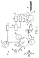
- Fig. 1 is a representational elevation view of a laser printer that includes the sheet media weight detector of the present invention.
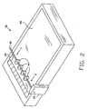
- Fig. 2 is a perspective view of a printer paper cassette showing the pick/feed roller and motor.
- Fig. 3 is a graph illustrating the input current and torque output for the pick/feed motor for different weight papers.
- Fig. 4 is a schematic diagram of a motor torque sensing circuit.
- Fig. 1 illustrates a conventional laser printer, designated by reference number 10, adapted for use with the invented sheet media detector.
- a computer transmits data representing an image to input port 12 of printer 10.
- This data is analyzed in formatter 14, which typically consists of a microprocessor and related programmable memory and page buffer. Formatter 14 formulates and stores an electronic representation of each page that is to be printed. Once a page has been formatted, it is transmitted to the page buffer.
- the page buffer breaks the electronic page into a series of lines or "strips" one dot wide. This strip of data is then sent to the printer controller 15. Controller 15, which also includes a microprocessor and programmable memory, drives laser 16 and controls the drive motor(s), fuser temperature and pressure, and the other print engine components and operating parameters.
- Each strip of data is used to modulate the light beam produced by laser 16.
- the light beam is reflected off a multifaceted spinning mirror 18.
- Photoconductive drum 20 rotates just enough that each successive scan of the light beam is recorded on drum 20 immediately after the previous scan. In this manner, each strip of data from the page buffer is recorded on photoconductive drum 20.
- Toner is electrostatically transferred from developing roller 28 toner onto photoconductive drum 20 according to the data previously recorded on the drum. The toner is thereafter transferred from photoconductive drum 20 onto paper 30 as paper 30 passes between drum 20 and transfer roller 32.
- Drum 20 is cleaned of excess toner with cleaning blade 36, completely discharged by discharge lamps 38 and then recharged by charging roller 26.
- Each sheet of paper 30 is advanced to the photoconductive drum 20 by a pick/feed mechanism 42.
- Pick/feed mechanism 42 includes feed rollers 44 coupled to a motor 45. Typically, a 24 volt d.c. servo motor is used to drive feed rollers 44.
- Motor 45 drives feed rollers 44 through shaft 46 and, usually, through a suitable reduction gear train (not shown). Motor 45 may also drive one or more other printer components, such as registration rollers 56.
- the paper stack 48 is positioned in input tray 50 to allow sliding passage of the top sheet of paper 30 into pick/feed area 40 at the urging of feed rollers 44. Feed rollers 44 have a frictionally adherent outer surface 54.
- feed rollers 44 In operation, as feed rollers 44 rotate, the frictionally adherent outer surface 54 of feed rollers 44 contacts the upper surface of paper 30 and pulls it into pick/feed area 40. As the leading edge of paper 30 moves through pick/feed area 40, it is engaged between a pair of registration rollers 56. Ramp 58 helps guide paper 30 into registration rollers 56. Registration rollers 56 advance paper 30 fully into image area 52 until it is engaged between drum 20 and transfer roller 32 and toner is applied as described above.
- feed rollers 44 apply a separation force F sufficient to drive paper 30 past edge separators 60 and over the next to top sheet in the paper stack 48.
- motor 45 applies the necessary pick/feed torque T through shaft 46 to turn feed rollers 44.
- Feed rollers 44 must apply a larger separation force F to heavy weight papers, which are heavier and stiffer than light weight papers, to successfully perform the pick/feed operation.
- Motor 45 must, therefore, apply a larger torque to shaft 46 to turn feed rollers 44.
- the amount of electrical current I drawn by motor 45 is related to the pick/feed torque T output of motor 45, which is related to the separation force F and the weight of paper 30.
- the input electrical current is related to the weight of paper 30.
- motor 45 will draw more current to deliver more torque for heavy weight papers. Conversely, motor 45 will draw less current to deliver less torque for light weight papers.
- This varying current draw is illustrated graphically in Fig. 3. Referring to Fig. 3, the solid line indicates the current I H drawn and torque T H delivered by motor 45 for heavy weight paper. The dotted line indicates the current I L drawn and torque T L delivered by motor 45 for light weight paper.
- the current and torque rise sharply during a pick/feed operation, indicated by reference number 62. Shortly after the pick/feed operation, the current and torque rise again, as indicated by reference number 64, as motor 45 engages and drives registration rollers 56.
- the relationship between the electrical current input and paper weight will vary depending on the components and configuration of a particular pick/feed system, this relationship can be established for each system empirically by measuring the motor current and torque values for different weight papers. Once this relationship is established, the input electrical current to motor 45 is measured and monitored by detector 66 and fed back to printer controller 15, as shown in Fig. 1, where the weight and thickness of paper 30 can be computed according to the appropriate algorithm or model.
- Detector 66 may be any suitable sensing circuit that measures the electrical current drawn by motor 45 during a pick/feed operation, or that measures the changes in electrical current drawn the pick/feed operations.
- a suitable sensing circuit is illustrated in Fig. 4. Referring to Fig. 4, input current I is shunted through sensing resistor 68. The voltage V i developed across sensing resistor 68 is inputted to operational amplifier 70. The output voltage V o from operational amplifier 70 is transmitted to printer controller 15. Various other sensing circuits could be used. The current drawn by motor 45 could be sensed magnetically to induce current through a sensing wire. This current is then inputted to a transimpedance operational amplifier (a current-voltage converter). Or, a Hall effect sensor could be used. The servo circuit feedback line could also be used to measure the electrical current drawn by motor 45.
- a transimpedance operational amplifier a current-voltage converter
- a Hall effect sensor could be used.
- the servo circuit feedback line could also be used to measure the electrical current drawn by
- detector 66 is calibrated to account for any drift or other changes occurring over time in the current drawn by motor 45.
- detector 66 is calibrated by measuring the output torque T i , and the corresponding current draw I i , just prior to the pick/feed operation. Then, the torque and current measured during the pick/feed operation T-T i and I- I i will reflect the separation force and paper weight, not any drift or other change in the pre-pick current draw.
- the output from detector 66 is utilized by printer controller 15 to automatically control and direct operations of those print engine components and printing parameters that depend on paper weight or thickness, such as fusing temperature and pressure, the speed at which the paper is advanced through the printer and the transfer current (the electric current or electro-static force that moves the toner onto the paper). These parameters and the components that control them can all be adjusted by controller 15 according to the output of detector 66.
Landscapes
- Engineering & Computer Science (AREA)
- Microelectronics & Electronic Packaging (AREA)
- Physics & Mathematics (AREA)
- General Physics & Mathematics (AREA)
- Controlling Sheets Or Webs (AREA)
- Handling Of Sheets (AREA)
- Sheets, Magazines, And Separation Thereof (AREA)
- Control Or Security For Electrophotography (AREA)
Applications Claiming Priority (2)
| Application Number | Priority Date | Filing Date | Title |
|---|---|---|---|
| US806993 | 1997-02-26 | ||
| US08/806,993 US5939646A (en) | 1997-02-26 | 1997-02-26 | Sheet media weight detector |
Publications (2)
| Publication Number | Publication Date |
|---|---|
| EP0863445A1 EP0863445A1 (en) | 1998-09-09 |
| EP0863445B1 true EP0863445B1 (en) | 2002-11-27 |
Family
ID=25195323
Family Applications (1)
| Application Number | Title | Priority Date | Filing Date |
|---|---|---|---|
| EP97115742A Expired - Lifetime EP0863445B1 (en) | 1997-02-26 | 1997-09-10 | Method for detecting the weight of sheet media |
Country Status (4)
| Country | Link |
|---|---|
| US (1) | US5939646A (enExample) |
| EP (1) | EP0863445B1 (enExample) |
| JP (1) | JPH10236674A (enExample) |
| DE (1) | DE69717413T2 (enExample) |
Families Citing this family (29)
| Publication number | Priority date | Publication date | Assignee | Title |
|---|---|---|---|---|
| US6726357B2 (en) | 2002-05-20 | 2004-04-27 | Hewlett-Packard Development Company, L.P. | Media identification system |
| JP4044838B2 (ja) * | 2002-12-24 | 2008-02-06 | 日本サーボ株式会社 | 給紙装置 |
| US7091427B2 (en) * | 2003-01-28 | 2006-08-15 | Hewlett-Packard Development Company, L.P. | Apparatus using resonance of a cavity to determine mass of a load |
| JP2005170651A (ja) * | 2003-12-15 | 2005-06-30 | Pfu Ltd | 給紙装置 |
| US7568850B2 (en) * | 2004-08-18 | 2009-08-04 | Hewlett-Packard Development Company, L.P. | Media stack control |
| US7416183B2 (en) * | 2005-06-06 | 2008-08-26 | Pitney Bowes Inc. | Postal weighing platform with integrated feeding and deskewing functions |
| DE102007014545B4 (de) | 2006-04-25 | 2018-09-27 | Heidelberger Druckmaschinen Ag | Verfahren zum Steuern eines Antriebes einer drucktechnischen Maschine und Anordnung zur Durchführung des Verfahrens |
| US8481870B2 (en) * | 2007-09-13 | 2013-07-09 | Raf Technology, Inc. | Active electronic damping for an in-line scale |
| US9018544B2 (en) | 2007-09-13 | 2015-04-28 | Raf Technology, Inc. | In-line conveyor scale with a primary first motor to provide constant torque, a secondary servo motor to provide fine-grained variable torque in response to a closed loop torque sensor, and a processor to assertain weight of an item conveved based on the closed loop servo motor response |
| US8481871B2 (en) | 2007-09-13 | 2013-07-09 | Raf Technology, Inc. | Dynamic thickness adaptation for an in-line scale |
| US8153911B2 (en) * | 2008-10-01 | 2012-04-10 | Raf Technology, Inc. | Dynamically weighing mail pieces in real time within an automated destination bar code sorter machine by temporarily accelerating the mail piece and capturing resulting closed loop motor torque sample data |
| US8530762B2 (en) * | 2007-09-13 | 2013-09-10 | Raf Technology, Inc. | Flatbed weigh system with vacuum capstan roller |
| US7687727B2 (en) * | 2007-09-13 | 2010-03-30 | Raf Technology, Inc. | Weigh on the fly |
| US8129635B2 (en) | 2007-09-13 | 2012-03-06 | Raf Technology, Inc. | Weighing a moving object using captured torque data |
| US7838781B2 (en) * | 2008-02-27 | 2010-11-23 | Motion Engineering Incorporated | System for determining the mass of an item in motion |
| JP2011038885A (ja) * | 2009-08-10 | 2011-02-24 | Toshiba Corp | 紙葉類の質量測定装置 |
| EP2339073A1 (en) | 2009-12-23 | 2011-06-29 | Perkins Engines Company Limited | A hydraulic system for a machine, a machine and a method of use |
| EP2400276B1 (en) * | 2010-06-16 | 2017-07-12 | RAF Technology, Inc. | In-line flatbed weigh system |
| US9091585B2 (en) | 2013-02-08 | 2015-07-28 | Raf Technology, Inc. | Smart phone scale that uses the built-in barometric pressure sensor or orientation sensors to calculate weight |
| US9564849B2 (en) | 2013-05-06 | 2017-02-07 | Raf Technology, Inc. | Scale for weighing flowing granular materials |
| US9598269B2 (en) * | 2014-04-04 | 2017-03-21 | David R. Hall | Motorized lifting device with a grooved drum for lifting a load and determining a weight of the load while lifting |
| US9567195B2 (en) * | 2013-05-13 | 2017-02-14 | Hall David R | Load distribution management for groups of motorized lifting devices |
| KR20160068478A (ko) * | 2014-12-05 | 2016-06-15 | 삼성전자주식회사 | 화상형성장치 및 화상형성장치의 동작 방법 |
| JP2017058481A (ja) * | 2015-09-15 | 2017-03-23 | 富士ゼロックス株式会社 | 定着装置、及び画像形成装置 |
| WO2017079749A1 (en) | 2015-11-05 | 2017-05-11 | Raf Technology, Inc. | High speed robotic weighing system |
| CN110944846B (zh) * | 2017-07-31 | 2022-02-22 | 惠普发展公司,有限责任合伙企业 | 介质检测器 |
| JP2020019603A (ja) * | 2018-07-31 | 2020-02-06 | エイチピー プリンティング コリア カンパニー リミテッドHP Printing Korea Co., Ltd. | 画像形成システム |
| WO2020046280A1 (en) | 2018-08-28 | 2020-03-05 | Hewlett-Packard Development Company, L.P. | Obstacle detection |
| CN114126885A (zh) * | 2019-07-23 | 2022-03-01 | 惠普发展公司,有限责任合伙企业 | 打印介质量的确定 |
Family Cites Families (10)
| Publication number | Priority date | Publication date | Assignee | Title |
|---|---|---|---|---|
| US4206912A (en) * | 1978-04-20 | 1980-06-10 | Joseph Wertheimer | Paper sensing mechanism |
| JPS574062A (en) * | 1980-06-06 | 1982-01-09 | Ricoh Co Ltd | Controller of copying machine |
| DE3541277A1 (de) * | 1985-11-22 | 1987-05-27 | Heidelberger Druckmasch Ag | Steuervorrichtung fuer einen druckmaschinenantriebsmotor oder dergleichen |
| US4852785A (en) * | 1987-11-24 | 1989-08-01 | Honeywell Bull Inc. | Printer paper control apparatus and method |
| US4835573A (en) * | 1988-04-29 | 1989-05-30 | International Business Machines Corporation | Machine control system utilizing paper parameter measurements |
| JP3149168B2 (ja) * | 1989-05-16 | 2001-03-26 | セイコーエプソン株式会社 | 印字装置 |
| JPH0566627A (ja) * | 1991-09-06 | 1993-03-19 | Canon Inc | 画像形成装置 |
| US5270563A (en) * | 1992-07-27 | 1993-12-14 | Eastman Kodak Company | Method and mechanism for sensing copy sheet weight |
| JPH06230626A (ja) * | 1993-02-04 | 1994-08-19 | Ricoh Co Ltd | 画像形成装置 |
| DE69418136T2 (de) * | 1993-10-22 | 1999-12-16 | Canon K.K., Tokio/Tokyo | Blattdickenmesseinrichtung in einem Abbildungsapparat |
-
1997
- 1997-02-26 US US08/806,993 patent/US5939646A/en not_active Expired - Lifetime
- 1997-09-10 DE DE69717413T patent/DE69717413T2/de not_active Expired - Lifetime
- 1997-09-10 EP EP97115742A patent/EP0863445B1/en not_active Expired - Lifetime
-
1998
- 1998-02-19 JP JP10037048A patent/JPH10236674A/ja active Pending
Also Published As
| Publication number | Publication date |
|---|---|
| DE69717413T2 (de) | 2003-09-25 |
| DE69717413D1 (de) | 2003-01-09 |
| US5939646A (en) | 1999-08-17 |
| EP0863445A1 (en) | 1998-09-09 |
| JPH10236674A (ja) | 1998-09-08 |
Similar Documents
| Publication | Publication Date | Title |
|---|---|---|
| EP0863445B1 (en) | Method for detecting the weight of sheet media | |
| US6311039B1 (en) | Sheet conveying apparatus and image forming apparatus provided with the same | |
| US7832723B2 (en) | Sheet feeding apparatus having a separating member and speed detecting unit | |
| EP0861799B1 (en) | Sheet media weight detector | |
| EP0902332B1 (en) | Print media weight detection system | |
| US8081890B2 (en) | Image forming apparatus, and unit removably installed in an image forming apparatus | |
| US9663310B2 (en) | Sheet feeding device and image forming apparatus | |
| US7331578B2 (en) | Sheet feeding device and method for detecting overlapping sheets | |
| US6883408B2 (en) | Method and device for feeding and cutting a rolled transfer paper with improved operability | |
| US8005388B2 (en) | Media velocity, media present and bubble control in an electrophotographic process | |
| EP2042935B1 (en) | Image forming apparatus | |
| US5983049A (en) | Conveyance speed control for medium conveyance apparatus | |
| JPH05313517A (ja) | 画像形成装置 | |
| JP4577579B2 (ja) | 画像形成装置 | |
| US12084306B2 (en) | Sheet feeding apparatus and image forming apparatus | |
| US7050734B2 (en) | Method of determining a relative speed between independently driven members in an image forming apparatus | |
| JPH07315595A (ja) | プリンタ用給紙装置 | |
| JPH07175387A (ja) | 電子写真装置 | |
| JP3548551B2 (ja) | 画像形成装置 | |
| US7403870B2 (en) | Trouble sensing device | |
| US5568227A (en) | Method and apparatus for transport speed optimization to minimize image smear | |
| JP3935795B2 (ja) | 用紙搬送装置および画像形成装置 | |
| US20020025205A1 (en) | Guide mechanism, paper feed control method, and image-forming device | |
| JP2003140410A (ja) | 画像形成装置 | |
| JP2583329B2 (ja) | シート供給装置 |
Legal Events
| Date | Code | Title | Description |
|---|---|---|---|
| PUAI | Public reference made under article 153(3) epc to a published international application that has entered the european phase |
Free format text: ORIGINAL CODE: 0009012 |
|
| AK | Designated contracting states |
Kind code of ref document: A1 Designated state(s): DE FR GB |
|
| AX | Request for extension of the european patent |
Free format text: AL;LT;LV;RO;SI |
|
| 17P | Request for examination filed |
Effective date: 19980903 |
|
| AKX | Designation fees paid |
Free format text: DE FR GB |
|
| RBV | Designated contracting states (corrected) |
Designated state(s): DE FR GB |
|
| RAP1 | Party data changed (applicant data changed or rights of an application transferred) |
Owner name: HEWLETT-PACKARD COMPANY, A DELAWARE CORPORATION |
|
| 17Q | First examination report despatched |
Effective date: 20010726 |
|
| RTI1 | Title (correction) |
Free format text: METHOD FOR DETECTING THE WEIGHT OF SHEET MEDIA |
|
| GRAG | Despatch of communication of intention to grant |
Free format text: ORIGINAL CODE: EPIDOS AGRA |
|
| RTI1 | Title (correction) |
Free format text: METHOD FOR DETECTING THE WEIGHT OF SHEET MEDIA |
|
| GRAG | Despatch of communication of intention to grant |
Free format text: ORIGINAL CODE: EPIDOS AGRA |
|
| GRAG | Despatch of communication of intention to grant |
Free format text: ORIGINAL CODE: EPIDOS AGRA |
|
| GRAH | Despatch of communication of intention to grant a patent |
Free format text: ORIGINAL CODE: EPIDOS IGRA |
|
| GRAH | Despatch of communication of intention to grant a patent |
Free format text: ORIGINAL CODE: EPIDOS IGRA |
|
| GRAA | (expected) grant |
Free format text: ORIGINAL CODE: 0009210 |
|
| AK | Designated contracting states |
Kind code of ref document: B1 Designated state(s): DE FR GB |
|
| REG | Reference to a national code |
Ref country code: GB Ref legal event code: FG4D |
|
| REF | Corresponds to: |
Ref document number: 69717413 Country of ref document: DE Date of ref document: 20030109 |
|
| ET | Fr: translation filed | ||
| PLBE | No opposition filed within time limit |
Free format text: ORIGINAL CODE: 0009261 |
|
| STAA | Information on the status of an ep patent application or granted ep patent |
Free format text: STATUS: NO OPPOSITION FILED WITHIN TIME LIMIT |
|
| 26N | No opposition filed |
Effective date: 20030828 |
|
| PGFP | Annual fee paid to national office [announced via postgrant information from national office to epo] |
Ref country code: FR Payment date: 20060918 Year of fee payment: 10 |
|
| PGFP | Annual fee paid to national office [announced via postgrant information from national office to epo] |
Ref country code: GB Payment date: 20060925 Year of fee payment: 10 |
|
| GBPC | Gb: european patent ceased through non-payment of renewal fee |
Effective date: 20070910 |
|
| REG | Reference to a national code |
Ref country code: FR Ref legal event code: ST Effective date: 20080531 |
|
| PG25 | Lapsed in a contracting state [announced via postgrant information from national office to epo] |
Ref country code: FR Free format text: LAPSE BECAUSE OF NON-PAYMENT OF DUE FEES Effective date: 20071001 |
|
| PG25 | Lapsed in a contracting state [announced via postgrant information from national office to epo] |
Ref country code: GB Free format text: LAPSE BECAUSE OF NON-PAYMENT OF DUE FEES Effective date: 20070910 |
|
| PGFP | Annual fee paid to national office [announced via postgrant information from national office to epo] |
Ref country code: DE Payment date: 20120927 Year of fee payment: 16 |
|
| REG | Reference to a national code |
Ref country code: DE Ref legal event code: R119 Ref document number: 69717413 Country of ref document: DE Effective date: 20140401 |
|
| PG25 | Lapsed in a contracting state [announced via postgrant information from national office to epo] |
Ref country code: DE Free format text: LAPSE BECAUSE OF NON-PAYMENT OF DUE FEES Effective date: 20140401 |