EP0863354B1 - Raccord de tuyau avec une pièce coupante pour tubes métalliques - Google Patents
Raccord de tuyau avec une pièce coupante pour tubes métalliques Download PDFInfo
- Publication number
- EP0863354B1 EP0863354B1 EP98103414A EP98103414A EP0863354B1 EP 0863354 B1 EP0863354 B1 EP 0863354B1 EP 98103414 A EP98103414 A EP 98103414A EP 98103414 A EP98103414 A EP 98103414A EP 0863354 B1 EP0863354 B1 EP 0863354B1
- Authority
- EP
- European Patent Office
- Prior art keywords
- ring
- screwed pipe
- pipe connection
- cone
- cutting ring
- Prior art date
- Legal status (The legal status is an assumption and is not a legal conclusion. Google has not performed a legal analysis and makes no representation as to the accuracy of the status listed.)
- Expired - Lifetime
Links
- 239000002184 metal Substances 0.000 title description 2
- 238000007789 sealing Methods 0.000 claims description 28
- 230000000694 effects Effects 0.000 claims description 10
- 239000000463 material Substances 0.000 claims description 7
- 229920001343 polytetrafluoroethylene Polymers 0.000 claims description 4
- 239000004810 polytetrafluoroethylene Substances 0.000 claims description 4
- 230000007704 transition Effects 0.000 claims description 4
- 239000013536 elastomeric material Substances 0.000 claims description 3
- 230000002093 peripheral effect Effects 0.000 description 22
- 230000006835 compression Effects 0.000 description 3
- 238000007906 compression Methods 0.000 description 3
- 239000003566 sealing material Substances 0.000 description 3
- 229920000459 Nitrile rubber Polymers 0.000 description 2
- 238000003780 insertion Methods 0.000 description 2
- 230000037431 insertion Effects 0.000 description 2
- 229920002449 FKM Polymers 0.000 description 1
- 240000006829 Ficus sundaica Species 0.000 description 1
- 229910000831 Steel Inorganic materials 0.000 description 1
- 230000009471 action Effects 0.000 description 1
- 230000004323 axial length Effects 0.000 description 1
- 230000008859 change Effects 0.000 description 1
- 239000011248 coating agent Substances 0.000 description 1
- 238000000576 coating method Methods 0.000 description 1
- 229920001577 copolymer Polymers 0.000 description 1
- 230000018109 developmental process Effects 0.000 description 1
- 229920001971 elastomer Polymers 0.000 description 1
- 239000000806 elastomer Substances 0.000 description 1
- 230000002349 favourable effect Effects 0.000 description 1
- 229920001973 fluoroelastomer Polymers 0.000 description 1
- 230000001771 impaired effect Effects 0.000 description 1
- 230000006872 improvement Effects 0.000 description 1
- 238000009434 installation Methods 0.000 description 1
- 238000000034 method Methods 0.000 description 1
- -1 polytetrafluoroethylene Polymers 0.000 description 1
- 230000008569 process Effects 0.000 description 1
- 230000009467 reduction Effects 0.000 description 1
- 239000010959 steel Substances 0.000 description 1
- 239000000126 substance Substances 0.000 description 1
Images


Classifications
-
- F—MECHANICAL ENGINEERING; LIGHTING; HEATING; WEAPONS; BLASTING
- F16—ENGINEERING ELEMENTS AND UNITS; GENERAL MEASURES FOR PRODUCING AND MAINTAINING EFFECTIVE FUNCTIONING OF MACHINES OR INSTALLATIONS; THERMAL INSULATION IN GENERAL
- F16L—PIPES; JOINTS OR FITTINGS FOR PIPES; SUPPORTS FOR PIPES, CABLES OR PROTECTIVE TUBING; MEANS FOR THERMAL INSULATION IN GENERAL
- F16L19/00—Joints in which sealing surfaces are pressed together by means of a member, e.g. a swivel nut, screwed on or into one of the joint parts
- F16L19/08—Joints in which sealing surfaces are pressed together by means of a member, e.g. a swivel nut, screwed on or into one of the joint parts with metal rings which bite into the wall of the pipe
- F16L19/10—Joints in which sealing surfaces are pressed together by means of a member, e.g. a swivel nut, screwed on or into one of the joint parts with metal rings which bite into the wall of the pipe the profile of the ring being altered
- F16L19/12—Joints in which sealing surfaces are pressed together by means of a member, e.g. a swivel nut, screwed on or into one of the joint parts with metal rings which bite into the wall of the pipe the profile of the ring being altered with additional sealing means
-
- Y—GENERAL TAGGING OF NEW TECHNOLOGICAL DEVELOPMENTS; GENERAL TAGGING OF CROSS-SECTIONAL TECHNOLOGIES SPANNING OVER SEVERAL SECTIONS OF THE IPC; TECHNICAL SUBJECTS COVERED BY FORMER USPC CROSS-REFERENCE ART COLLECTIONS [XRACs] AND DIGESTS
- Y10—TECHNICAL SUBJECTS COVERED BY FORMER USPC
- Y10S—TECHNICAL SUBJECTS COVERED BY FORMER USPC CROSS-REFERENCE ART COLLECTIONS [XRACs] AND DIGESTS
- Y10S285/00—Pipe joints or couplings
- Y10S285/91—Gaskets
-
- Y—GENERAL TAGGING OF NEW TECHNOLOGICAL DEVELOPMENTS; GENERAL TAGGING OF CROSS-SECTIONAL TECHNOLOGIES SPANNING OVER SEVERAL SECTIONS OF THE IPC; TECHNICAL SUBJECTS COVERED BY FORMER USPC CROSS-REFERENCE ART COLLECTIONS [XRACs] AND DIGESTS
- Y10—TECHNICAL SUBJECTS COVERED BY FORMER USPC
- Y10S—TECHNICAL SUBJECTS COVERED BY FORMER USPC CROSS-REFERENCE ART COLLECTIONS [XRACs] AND DIGESTS
- Y10S285/00—Pipe joints or couplings
- Y10S285/918—O-ring
Definitions
- the present invention relates to a pipe fitting for connecting a in particular metallic pipeline, with a receiving opening for the Pipe having connecting piece, one with the connecting piece screwable union nut and one between the connecting piece and the Union nut arranged, metallic cutting ring, the cutting ring with an outer cone with an inner cone of the connecting piece interacts that he radially after tightening the union nut is deformed on the inside and with at least one cutting edge under notch effect form-fitting cuts in the material of the pipeline, and the cutting ring following the outer cone, a substantially radial stop surface for has suit-limiting system on an end face of the connecting piece, and an elastomer in an annular groove in the area of the outer cone of the cutting ring Circumferential seal is arranged to rest in the inner cone of the connecting piece.
- An elastomeric sealing element should be approximately in the middle of the conical one Be arranged area between the outer and inner cone.
- the sealing element should be thicker than the depth of the ring groove, so that the sealing element before the cutting ring assembly protrudes radially from the ring groove on both sides, which increases during assembly the sealing material could flow away. That would make it Sealing effect at least impaired.
- DE 43 04 534 A1 describes such a “connection system”, with only a metallic seal over two in the pipe incisive cutting edges is provided.
- This publication deals with first and foremost with the improvement of the mechanical support of the pipeline the cutting ring made of a hardened or solidified material should exist.
- the cutting ring can at least in some areas Reducing friction - and thus improving the sliding properties - Have coating, which may contain PTFE in particular.
- FR-A-2 568 665 also discloses a similar pipe screw connection.
- a sealing ring is provided, which is axially in front the cutting ring in the gap between the pipeline and the socket inner cone is arranged. Under certain circumstances, this can "flow away" of the sealing material, especially in the gap between the nozzle and the pipe. Of course, this is unfavorable for the sealing effect.
- a free area is formed such that in the Installation position between the free space and the inner cone of the nozzle, a free space given is. This is supposed to cause radial voltage peaks at the front end of the Connection piece can be avoided.
- the present invention has for its object a pipe fitting Generic type to improve especially with regard to the sealing effect.
- this is achieved in that the elastomeric peripheral seal in Transitional area between the outer cone and the stop surface of the Cutting ring is arranged, for which purpose the annular groove receiving the peripheral seal is formed between the outer cone and the stop surface and directly into the Stop surface merges, so that in the mounting position, the peripheral seal between the cutting ring on the one hand and at least one directly on the Sub-area of the inner cone of the connecting piece on the other hand is arranged under elastic prestress.
- the peripheral seal is either only in the cone area mainly radial sealing effect or in combination both in the cone area as well as between the stop surface and the nozzle end face with radial as well axial sealing effect arranged.
- the stop surface of the Cutting ring indirectly over a section of the circumferential seal for contact with the End face of the connecting piece.
- the circumferential seal receiving annular groove has a groove base which is in terms of its diameter At least in some areas, it is smaller than the largest diameter on the end face End of the inner cone of the connecting piece is that in a thereby to the inner cone back formed chamber a peripheral seal can be housed, the one for a compression seal has a sufficiently large volume.
- This can also also by a certain configuration of the circumferential contour of the annular groove or Nutgrundes are influenced, including some design variants below be described in more detail. With the contour of the ring groove can also do that Deformation behavior of the cutting ring when tightening the screw connection favorable to be influenced.
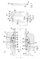
- a pipe fitting 1 generally exists i.e. in all the illustrated embodiments a base body 2, which is only indicated, and which is at least an externally threaded connection piece 4, onto which a union nut 6 is screwed or can be screwed on.
- the connecting piece 4 has a Receiving opening 8 for one end 10a one - in particular from Steel or other metal existing - pipeline 10.
- the receiving opening 8 is expedient through a bore formed by a radial ring stage 12 in a Reduced diameter, further into the base body 2 extending and with the inner diameter of the pipeline 10 preferably passes approximately aligned channel 14. there the ring stage 12 forms a stop for the end 10a of the Pipeline 10.
- the collar 16 has or encloses one Feed-through opening 20 for the pipeline 10.
- the cutting ring 18 consists of a in the space between the connecting piece 4 and the union nut 6 and the collar 16 arranged Base ring part 24 and one of these in Direction of the connecting piece 4 extending, in the ring thickness reduced, tubular-like cutting ring part 26.
- the receiving opening 8 of the connecting piece 4 widens in their end area facing the union nut 6 an inner cone 28.
- the inner cone 28 engages Cutting ring 18 with the cutting ring part 26 and acts here with a tapered outer cone 30 with the Inner cone 28 together in such a way that by axial bracing when tightening the union nut 6 the cutting ring 18 in Area of the cutting ring part 26 deformed radially inwards (compressed) and thereby preferably with two axially spaced, radially inwardly facing, annular Cutting edges 32 with a notch effect in particular form-fitting penetrates into the material of the pipeline 10.
- the base ring part 24 preferably also has on it the cutting ring part 26 axially facing away from itself end tapered outer conical surface 34, the a corresponding inner conical surface 36 of the collar 16 the union nut 6 rests. This will also result in this Area a wedge effect for the radial pressing of the Cutting ring 18 and also self-centering achieved.
- the cutting ring 18 or the base ring part 24 has its side facing the cutting ring part 26 in essential radial stop surface 38, which in a tightened assembly position (see each the lower half of the figure in Fig. 1 and 5 and Fig. 9) for tightening Position on an end face 40 of the connecting piece 4 arrives.
- the cutting ring 18 is used on the one hand for mechanical mounting the pipeline 10 through one over the cutting edges 32 positive connection reached.
- the Cutting ring 18 basically also has a metallic sealing function over those cutting into the pipeline 10 Cutting edges 32 and over the cones 28, 30.
- the cutting ring 18 now has in the transition region between the outer cone 30 and the stop surface 38 an elastomeric peripheral seal 44, in such a way that that in the mounting position the peripheral seal 44 between the cutting ring 18 on the one hand and the inner cone 28 and / or the end face 40 of the connecting piece 4 on the other hand is arranged chambered under elastic bias.
- the peripheral seal 44 essentially only in the area of the adjacent Cones, i.e. the outer cone 30 and the inner cone 28, chambered, so that here the stop surface 38 immediately comes to rest on the end face 40.
- peripheral seal 44 is additional also axially between the stop surface 38 and the end face 40 chambered, so that here the stop surface 38th indirectly via the peripheral seal 44 on the end face 40 is present.
- the peripheral seal 44 is expedient in a between the outer cone 30 and the stop surface 38 formed annular groove 46 of the cutting ring 18 is arranged.
- This annular groove 46 preferably goes directly into the stop surface 38 over. This means that the ring groove 46 on the two axial sides of essentially radial Flank surfaces 48 is limited, which is the outer cone 30 axially facing flank surface 48 essentially lies in the same plane with the stop surface 38.
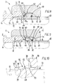
- the annular groove 46 has a groove base 50 which - seen in axial section - is conical with a certain cone angle ⁇ (see FIG. 2).
- ⁇ cone angle
- the conical groove base 50 has, in particular on its side axially facing the outer cone 30, a smallest diameter D 1 (see FIG. 2), which - even before the first assembly-related deformation of the cutting ring 18 - is in any case smaller than the largest diameter D 2 (see FIG 1) is at the front end of the inner cone 28 of the connecting piece 4.
- the diameter D 1 of the groove base 50 is nominally about 0.4 to 0.5 mm below the diameter D 2 at the end of the inner cone 28. According to the aforementioned DIN, this is the largest diameter D 2 of the inner cone 28, for example 14.3 mm, the groove base has a diameter D 1 of in particular approximately 13.9 mm.
- the cone angle ⁇ is preferably in the range from approximately 10 ° to 15 ° and is in particular approximately 12 °, ie 2 x approximately 6 ° (1 ⁇ 2 ⁇ ) to the longitudinal axis.
- contour of the ring groove 46 can advantageously be a profile ring for the peripheral seal 44 52 according to FIGS. 3 and 4 can be used.
- This profile ring 52 has a substantially rectangular ring cross section on, before assembly, i.e. before insertion into the annular groove 46, an essentially hollow cylindrical, has a tubular shape. After insertion in the annular groove 46 is adapted to the conical shape the groove bottom 50; s. Fig. 1 and 2.
- can 3a and 4a also a profile ring 54 with an im essential triangular ring cross section can be used.
- this profile ring 54 preferably has radially inner ring area approximately in cross section rectangular base ring part with a radially outside subsequent, in particular isosceles triangular area. This results in a radially outward direction protruding sealing edge 56 through a corner of the triangular cross section is formed.
- the profile ring 54 Before assembly according to FIG. 3a, an essentially cylindrical one Inner surface, which is then assembled in the Adapts condition to the conical groove base 50.
- the annular groove 46 has a groove base 58, 1 which is essentially cylindrical in axial section.
- the ratio of the diameter D 1 of this cylindrical groove base 58 to the largest diameter D 2 of the socket inner cone 28 corresponds to the embodiment according to FIGS. 1 to 4a.
- a profile ring 60 is used as an example as circumferential seal 44, which according to FIGS. 5 and 7 has an essentially L-shaped ring cross section with an axial ring section 62, in particular facing the outer cone 30, and a ring section 64 extending radially outwards.
- the size of these sections 62, 64 is such that after assembly - see FIG. 5, lower half - the radial ring section 64 is arranged between the stop surface 38 of the cutting ring 18 and the end face 40 of the connecting piece 4.
- the annular groove 44 has a groove base 66 which seen in axial section - in an approximately central region 68 convex and preferably in both flank areas 70 is concave (see in particular Fig. 10).
- the curvatures expediently merge into one another about.
- This contour of the annular groove 46 is a good one Seal compression reached.
- this contour is also deformable, what the deformation of the cutting ring concerns when tightening the screw connection.
- the two concavely curved flank regions 70 of the annular groove 46 define a fictitious circumferential plane 72 which - essentially analogously to the embodiment according to FIGS. 1 to 4a - also in axial section a certain cone angle ⁇ (in Fig. 10 half the cone angle 1 ⁇ 2 ⁇ is shown) is conical. It is preferably provided that due to the cone angle ⁇ the flank area 70 axially closest to the outer cone 30 is smaller in diameter than the other flank area 70. In principle, however, this could also be provided vice versa. In any case, here too the smaller diameter D 1 is in any case smaller than the largest diameter D 2 of the inner cone 28.
- the size of the cone angle ⁇ preferably corresponds to the embodiment according to FIGS.
- the two flank regions 70 of the annular groove 46 define a fictitious cylindrical circumferential plane, which in turn has a diameter corresponding to (D 1 ) which is smaller than the largest diameter (D 2 ) of the Inner cone 28 is.
- the Ring cross-sectional contour is chosen such that the profile ring 74 in the mounting position (Fig. 9) by the Fills the annular groove 46 and the chamber resulting in the inner cone 28, but is elastically compressed and therefore under tension stands.
- the circumferential seal is present in all of the illustrated embodiments 44 or the respective profile ring 52, 54, 60 or 74 from a suitable elastomeric material.
- a material using NBR is suitable (Nitrile rubber according to DIN ISO 1629) and / or PTFE (polytetrafluoroethylene according to DIN 7728 T1).
- a multiple for The material used for seals is also VITON (brand from DuPont); these are heat and chemical-resistant, vulcanizable fluoroelastomers based on vinylidene fluoride-hexafluoropropylene copolymers.
- an additional elastic sealing ring 76 for radial inner seal between the cutting ring 18 and the Pipeline 10 provided.
- This additional sealing ring 76 is useful in an inner annular groove 78 of the cutting ring 18 arranged, in particular approximately in the middle Area of the base ring part 24 or slightly from the Center in the direction of the collar 16 of the union nut 6 offset (see FIGS. 8 and 9).
- the additional sealing ring 76 is on the one hand when tightening by the action of the conical surfaces 34 and 36 braced inside.
- the stop surface 38 of the cutting ring 18 slightly radial at least before the first assembly outwards and axially in the direction of the end face 40 of the connecting piece 4 inclined, that is, slightly hollow-conical, runs that a deformation when tightening the union nut 6 of the cutting ring 18 for the purpose of area-wise, radially inward compression against the Pipeline 10 takes place, in particular in the area of the additional sealing ring 76.
- the inclined, light The conical shape of the stop surface 38 is somewhat in FIG. 10 exaggerated.
- the Cutting ring 18 shown in FIG. 8 first with an outer Ring edge 80 of the stop surface 38 for abutment against the end face 40 of the nozzle 4.
- Fig. 9 it is illustrated that in the tightened mounting position the stop surface 38 then essentially over the entire surface of the end face 40 is applied after the cutting ring is in accordance with the drawn arrow 82 has deformed. Because of this deformation results in the approximately central area of the cutting ring, i.e. approximately in the transition between the cutting ring part 26 and the base ring part 24, a slight radial Bulge 84.
- the cutting ring becomes arcuate pressed radially onto the pipeline 10.
- the sealing ring 76 thereby receives an effective backlash-free tension the circumference of the pipeline 10.
- the nut is tightened 6 advantageously by the striking block Cutting ring 18 noticeably limited.
- the material of the seal 44 can thus tighten the screw connection - instead of up to a precisely defined stop position - over an approximately depth T appropriate area of attraction; it becomes practically one "Tightening reserve" to compensate for any unfavorable tolerance of the Items reached.
- the profile ring 60 can be integrally connected to the cutting ring 18, e.g. vulcanized or molded his.
Landscapes
- Engineering & Computer Science (AREA)
- General Engineering & Computer Science (AREA)
- Mechanical Engineering (AREA)
- Gasket Seals (AREA)
- Joints With Pressure Members (AREA)
Claims (15)
- Raccord vissé (1) pour raccorder une conduite (10), en particulier métallique, avec un embout présentant une ouverture (8) pour la conduite (10), avec un écrou-raccord (6) pouvant être vissé avec l'embout (4) ainsi qu'avec une bague coupante (18) métallique placée entre l'embout (4) et l'écrou-raccord (6), la bague coupante (18) avec un cône extérieur (30) interagissant avec un cône intérieur (28) de l'embout (4) de telle façon qu'elle se déforme vers l'intérieur de manière radiale dans certaines zones lorsqu'on serre l'écrou-raccord (6) et pénètre par concordance de forme dans le matériau de la tuyauterie (10) avec au moins une arête coupante (32) sous l'action du cisaillement et la bague coupante (18) présentant, au niveau du raccordement avec le cône extérieur (30) une surface d'arrêt (38) essentiellement radiale qui vient plaquer, pour limiter le serrage, contre une face frontale (40) de l'embout (4) et un joint périphérique élastomère (44) étant placé dans une rainure annulaire (46) au niveau du cône extérieur (30) de la bague coupante (18) pour plaquer dans le cône intérieur (28) de l'embout (4),
caractérisé en ce que le joint périphérique élastomère (44) est placé dans la zone intermédiaire entre le cône extérieur (30) et la surface d'arrêt (38) de la bague coupante (18), ce pourquoi la gorge annulaire (46) recevant le joint périphérique (44) est située entre le côté extérieur (30) et la surface d'arrêt (38) et débouche directement sur la surface d'arrêt (38) de sorte qu'en l'état monté, le joint périphérique (44) est placé sous précontrainte élastique entre la bague coupante (18) d'une part et au moins une partie du cône intérieur (28) de l'embout (4) directement raccordée à la face frontale (40) d'autre part. - Raccord vissé selon revendication 1,
caractérisé en ce que la gorge annulaire (46) présente un fond de gorge (58) de forme essentiellement conique en coupe axiale et un diamètre (D1) inférieur au plus grand diamètre (D2) sur l'extrémité, côté frontal, du cône intérieur (28) de l'embout (4). - Raccord vissé selon revendication 1,
caractérisé en ce que la gorge annulaire (46) présente un fond de gorge (50) configuré, en coupe axiale, avec un angle conique (β) donné et - en particulier sur le côté tourné axialement vers le cône extérieur (30) - présente un diamètre minimal (D1) plus petit que le plus grand diamètre (D2) sur l'extrémité, coté frontal, du cône intérieur (28) de l'embout (4). - Raccord vissé selon revendication 1,
caractérisé en ce que la gorge annulaire (44) présente un fond de gorge (66) qui - vu en coupe axiale - est convexe dans une zone approximativement centrale (68) et, de préférence, concave sur les deux flancs (70). - Raccord vissé selon revendication 4,
caractérisé en ce que les deux flancs (70) concaves de la gorge annulaire (46) définissent un niveau périphérique cylindrique fictif présentant un diamètre (D1) plus petit que le plus grand diamètre (D2) à l'extrémité, côté frontal, du cône intérieur (28) de l'embout (4). - Raccord vissé selon revendication 4,
caractérisé en ce que les deux flancs (70) concaves de la gorge annulaire (46) définissent un niveau périphérique fictif (72) ayant un angle conique (β) donné en coupe axiale, le plus petit diamètre, en particulier du flanc concave (70) axialement le plus proche du cône extérieur (30) étant inférieur au plus grand diamètre (D2) sur l'extrémité, coté frontal, du cône intérieur (28) de l'embout (4). - Raccord vissé selon revendications 3 ou 6,
caractérisé en ce que l'angle conique (β) du fond de gorge (50;66) est approximativement égal à 10 à 15°, en particulier approximativement égal à 12°. - Raccord vissé selon l'une des revendications 1 à 7,
caractérisé en ce que le joint périphérique (44) est formé par une bague profilée (52; 54; 60; 74) constituée d'un matériau élastomère, en particulier de NBR et/ou de PTFE. - Raccord vissé selon revendication 8,
caractérisé en ce que la bague profilée (52) présente une section essentiellement rectangulaire. - Raccord vissé selon revendication 8,
caractérisé en ce que la bague profilée (54) présente une section essentiellement triangulaire avec une arête d'étanchéité dépassant vers l'extérieur de façon approximativement radiale. - Raccord vissé selon revendication 8,
caractérisé en ce que la bague profilée (60) présente une section essentiellement en forme de L avec un tronçon (62) axial tourné en particulier vers le cône extérieur (30) et un tronçon (64) radial, le tronçon radial (64) étant placé après le montage de préférence entre la surface d'arrêt (38) de la bague coupante (18) et la face frontale (40) de l'embout (4). - Raccord vissé selon revendication 11,
caractérisé en ce que la bague profilée (60) présente, sur le côté du tronçon radial (64) tourné vers l'embout (4) au moins une nervure (90), en forme de cloison de gorge, faisant le tour de façon concentrique, de préférence au moins deux nervures (90) faisant le tour de façon concentrique séparées par des creux axiaux (92) en forme de gorge situés radialement entre. - Raccord vissé selon l'une des revendications 1 à 12,
caractérisé par une bague d'étanchéité (76) élastique supplémentaire destinée à l'étanchéité radialement interne entre la bague coupante (18) et la tuyauterie (10). - Raccord vissé selon revendication 13,
caractérisé en ce que la bague d'étanchéité supplémentaire (76) est placée dans une gorge interne (78) de la bague coupante (18). - Raccord vissé selon l'une des revendications 1 à 14,
caractérisé en ce que la surface d'arrêt (38) de la bague coupante (18) est légèrement inclinée vers l'extérieur de façon radiale et en direction de la face frontale (40) de l'embout (4) de façon axiale, en ce que, lors du serrage de l'écrou-raccord (6), la bague coupante (18) se déforme afin d'assurer une compression contre la tuyauterie (10) vers l'intérieur de façon radiale et ce, en particulier, dans la zone de la bague d'étanchéité supplémentaire (76).
Applications Claiming Priority (2)
| Application Number | Priority Date | Filing Date | Title |
|---|---|---|---|
| DE19709464A DE19709464C2 (de) | 1997-03-07 | 1997-03-07 | Rohrverschraubung mit Schneidring für metallische Rohrleitungen |
| DE19709464 | 1997-03-07 |
Publications (2)
| Publication Number | Publication Date |
|---|---|
| EP0863354A1 EP0863354A1 (fr) | 1998-09-09 |
| EP0863354B1 true EP0863354B1 (fr) | 2001-12-19 |
Family
ID=7822623
Family Applications (1)
| Application Number | Title | Priority Date | Filing Date |
|---|---|---|---|
| EP98103414A Expired - Lifetime EP0863354B1 (fr) | 1997-03-07 | 1998-02-27 | Raccord de tuyau avec une pièce coupante pour tubes métalliques |
Country Status (4)
| Country | Link |
|---|---|
| US (1) | US6073976A (fr) |
| EP (1) | EP0863354B1 (fr) |
| DE (2) | DE19709464C2 (fr) |
| ES (1) | ES2169450T3 (fr) |
Cited By (3)
| Publication number | Priority date | Publication date | Assignee | Title |
|---|---|---|---|---|
| WO2008154950A1 (fr) | 2007-06-18 | 2008-12-24 | Weidmann Ltd. | Système de raccordement pour un raccord vissé |
| DE202017100918U1 (de) | 2017-02-20 | 2017-04-07 | Walter Stauffenberg Gmbh & Co. Kg | Verbindungsanordnung zum Anschluss einer Rohrleitung |
| EP3364086A1 (fr) | 2017-02-20 | 2018-08-22 | Walter Stauffenberg Gmbh & Co. Kg | Système de liaison destiné à raccorder une conduite |
Families Citing this family (66)
| Publication number | Priority date | Publication date | Assignee | Title |
|---|---|---|---|---|
| TW473600B (en) * | 1997-04-15 | 2002-01-21 | Swagelok Co | Tube fitting, rear ferrule for a two ferrule tube fitting and ferrule for a tube fitting and a non-flared tube fitting |
| US7614668B1 (en) * | 1997-04-15 | 2009-11-10 | Swagelok Company | Ferrule with plural inner diameters |
| US6629708B2 (en) * | 1997-04-15 | 2003-10-07 | Swagelok Company | Ferrule with relief to reduce galling |
| US5882050A (en) * | 1997-04-15 | 1999-03-16 | Williams; Peter C. | Ferrule with relief to reduce galling |
| DE19855795B4 (de) * | 1998-12-03 | 2006-04-13 | Voss Fluid Gmbh + Co. Kg | Schneidringverschraubung für Druckmittel-Rohrleitungen |
| MXPA02002878A (es) * | 1999-09-13 | 2003-07-21 | Swagelok Co | Accesorio de tubo con medios indicadores. |
| US7194817B2 (en) | 1999-09-13 | 2007-03-27 | Swagelok Company | Intrinsic gauging for tube fittings |
| US6640457B2 (en) * | 1999-09-13 | 2003-11-04 | Swagelok Company | Intrinsic gauging for tube fittings |
| EP1536175A3 (fr) * | 1999-09-13 | 2005-10-19 | Swagelok Company | Raccord pourvu d'un dispositif indicateur |
| US6279242B1 (en) | 1999-09-13 | 2001-08-28 | Swagelok Company | Intrinsic gauging for tube fittings |
| DE10011146A1 (de) * | 2000-03-07 | 2001-09-27 | Parker Hannifin Gmbh | Schraubverbindung |
| US7175208B2 (en) * | 2000-10-12 | 2007-02-13 | Wellstream International Limited | High temperature end fitting and method of use |
| KR100861970B1 (ko) * | 2001-02-06 | 2008-10-07 | 스와겔로크 컴패니 | 스테인레스강관용 관 이음쇠 |
| US7416225B2 (en) * | 2001-02-06 | 2008-08-26 | Swagelok Company | Fitting for metal pipe and tubing |
| US7066496B2 (en) * | 2001-02-06 | 2006-06-27 | Swagelok Company | Fitting with separable gripping device for pipe and tube |
| KR20080091251A (ko) * | 2001-02-06 | 2008-10-09 | 스와겔로크 컴패니 | 내부 풀업 표시를 갖는 이음쇠 |
| US7407196B2 (en) * | 2003-08-06 | 2008-08-05 | Swagelok Company | Tube fitting with separable tube gripping device |
| US20030197378A1 (en) * | 2002-04-18 | 2003-10-23 | Allstead Bradley E. | Sealing compression ferrule for plumbing connection fitting |
| FR2855863B1 (fr) * | 2003-06-03 | 2006-12-15 | Legris Sa | Dispositif de raccordement pour tuyauteries de fluides a haute pression |
| US20050035594A1 (en) * | 2003-08-13 | 2005-02-17 | Kiely Kenneth M. | Weatherproof compression connecting assembly for securing electrical metal tubing |
| US20050035593A1 (en) * | 2003-08-13 | 2005-02-17 | Delbert Auray | Electrical connection assembly with unitary sealing and compression ring |
| US7390027B2 (en) * | 2003-08-13 | 2008-06-24 | Bridgeport Fittings, Inc. | Weatherproof compression connecting assembly for securing electrical metal tubing |
| WO2005043024A1 (fr) * | 2003-11-03 | 2005-05-12 | Swagelok Company | Raccord pour tuyau metallique et tube |
| US7497483B2 (en) * | 2004-04-22 | 2009-03-03 | Swagelok Company | Fitting for tube and pipe with cartridge |
| TW200602577A (en) * | 2004-04-22 | 2006-01-16 | Swagelok Co | Fitting for tube and pipe |
| DE202004012473U1 (de) * | 2004-08-10 | 2006-01-26 | Voss Fluid Gmbh + Co. Kg | Metallischer Schneidring |
| GB2466098B (en) | 2005-02-25 | 2010-12-15 | Parker Hannifin Plc | A coupling |
| US20060237962A1 (en) * | 2005-04-22 | 2006-10-26 | Anderson Bret M | Tool for preparing fitting and conduit connection |
| JP5023721B2 (ja) * | 2006-01-31 | 2012-09-12 | ダイキン工業株式会社 | 食い込み式管接続構造 |
| DE102006023650A1 (de) * | 2006-05-18 | 2007-11-22 | Eifeler Maschinenbau Gmbh | Rohrverbindung mit einem umgeformten Rohr |
| WO2008030375A2 (fr) * | 2006-09-01 | 2008-03-13 | Swagelok Company | Raccord pour conduits de fluide |
| BRPI0717872A2 (pt) | 2006-11-02 | 2013-10-29 | Swagelok Co | Içamento por meio de encaixe de torque |
| CN1987187B (zh) | 2006-12-11 | 2010-04-14 | 浙江华夏阀门有限公司 | 单双箍共体式挤压连接管接件 |
| ES2384991T3 (es) * | 2007-06-18 | 2012-07-16 | Weidmann Ltd. | Disposición de conexión para una unión roscada de tubos |
| CN101809350A (zh) * | 2007-07-27 | 2010-08-18 | 斯瓦戈洛克公司 | 用于管子或管道接头的锥形螺母 |
| CN101821541A (zh) | 2007-08-03 | 2010-09-01 | 斯瓦戈洛克公司 | 通过扭矩套圈管接头接上 |
| US10215315B2 (en) * | 2008-09-05 | 2019-02-26 | Parker-Hannifin Corporation | Tube compression fitting and flared fitting used with connection body and method of making same |
| US20100059996A1 (en) * | 2008-09-05 | 2010-03-11 | Ciprich Samuel D | Tube compression fitting and flared fitting used with connection body and method of making same |
| EP2370723B1 (fr) * | 2008-12-10 | 2017-02-15 | Swagelok Company | Ensemble virole pour emboîtement de conduits |
| JP4798247B2 (ja) * | 2009-03-31 | 2011-10-19 | 株式会社デンソー | コネクタ |
| GB2482175B (en) * | 2010-07-23 | 2016-01-13 | Agilent Technologies Inc | Fitting element with bio-compatible sealing |
| CN103201551B (zh) * | 2010-10-15 | 2016-09-07 | 世伟洛克公司 | 具有套管的推动连接管接头 |
| DE102011053012A1 (de) | 2011-08-26 | 2013-02-28 | Voss Fluid Gmbh | Schneidring-Vormontagegerät für Rohrverschraubungen |
| JP5276215B1 (ja) * | 2012-09-19 | 2013-08-28 | 井上スダレ株式会社 | 冷媒用管継手構造 |
| US9343883B2 (en) | 2013-03-14 | 2016-05-17 | Bridgeport Fittings, Inc. | Raintight compression connector and raintight compression coupler for securing electrical metallic tubing or rigid metallic conduit |
| EP3049189B1 (fr) * | 2013-09-25 | 2019-10-30 | United Technologies Corporation | Buse et pistolet de pulvérisation à froid simplifiés |
| US9903518B2 (en) | 2013-10-24 | 2018-02-27 | Swagelok Company | Single action push to connect conduit fitting |
| US10240694B2 (en) | 2013-10-31 | 2019-03-26 | Bridgeport Fittings, Inc. | Co-molded sealing ring for use in an electrical fitting, and a raintight compression connector and raintight compression coupler incorporating a co-molded sealing ring |
| US9787070B2 (en) | 2013-10-31 | 2017-10-10 | Bridgeport Fittings, Inc. | Raintight compression connector and raintight compression coupler for securing electrical metallic tubing or rigid metallic conduit |
| USD787648S1 (en) | 2013-10-31 | 2017-05-23 | Bridgeport Fittings, Inc. | Raintight fitting connector body |
| CN103645006A (zh) * | 2013-11-14 | 2014-03-19 | 无锡市鑫盛换热器制造有限公司 | 防松锁紧压力测试接头 |
| EP3140580B1 (fr) | 2014-05-09 | 2020-03-25 | Swagelok Company | Raccord de conduit à composants conçus pour faciliter l'assemblage |
| US10458582B2 (en) | 2015-04-23 | 2019-10-29 | Swagelok Company | Single action push to connect conduit fitting with colleting |
| JP6845155B2 (ja) | 2015-04-23 | 2021-03-17 | スウエイジロク・カンパニー | コレットを有する導管継手の単動押動式接続 |
| JP6224806B2 (ja) * | 2016-01-15 | 2017-11-01 | ダイキン工業株式会社 | 管継手及び空気調和装置 |
| WO2017122504A1 (fr) * | 2016-01-15 | 2017-07-20 | ダイキン工業株式会社 | Raccord de tuyaux et climatiseur |
| CN108884953B (zh) | 2016-02-09 | 2021-04-27 | 世伟洛克公司 | 用于管道配件的套圈 |
| CN109073120B (zh) | 2016-03-23 | 2021-02-19 | 斯瓦戈洛克公司 | 具有行程阻抗特征的导管配件 |
| DE102016122095A1 (de) | 2016-10-10 | 2018-04-12 | Voss Fluid Gmbh | Vorrichtung und Verfahren zur Montage eines Schneidrings |
| EP3306162B1 (fr) | 2016-10-10 | 2020-08-05 | VOSS Fluid GmbH | Dispositif et procédé de montage d'une bague coupante |
| CN107448713A (zh) * | 2017-08-24 | 2017-12-08 | 海盐双赢管件制造有限公司 | 一种卡套式密封软管接头 |
| CN108326791B (zh) * | 2018-01-04 | 2019-10-18 | 湖南吉利汽车部件有限公司 | 一种汽车高压管线预紧工装 |
| US11703165B2 (en) | 2018-04-27 | 2023-07-18 | Swagelok Company | Ferrule assembly for conduit fitting |
| DE102018117593B4 (de) | 2018-07-20 | 2022-01-13 | Voss Fluid Gmbh | Schneidringverschraubung |
| EP3948042A1 (fr) | 2019-04-01 | 2022-02-09 | Swagelok Company | Ensembles et agencements de raccord de conduit à pousser pour raccordement |
| EP4281694A1 (fr) * | 2021-01-22 | 2023-11-29 | Danfoss Power Solutions II Technology A/S | Systèmes de raccord à tube |
Family Cites Families (19)
| Publication number | Priority date | Publication date | Assignee | Title |
|---|---|---|---|---|
| US2437632A (en) | 1944-11-13 | 1948-03-09 | Parker Appliance Co | Coupling for tubes |
| US2529552A (en) | 1946-05-24 | 1950-11-14 | Weatherhead Co | Tube coupling with rubber seal |
| JPS5025649B1 (fr) * | 1970-12-05 | 1975-08-26 | ||
| GB1362205A (en) * | 1971-01-26 | 1974-07-30 | Alenco Ind Components Ltd | Pipe coupling |
| BE792460A (fr) * | 1971-12-11 | 1973-03-30 | Armaturenfabrik Hermann Fa | Raccord filete pour tuyau |
| FR2406773A1 (fr) * | 1977-10-24 | 1979-05-18 | Legris France Sa | Procede de montage de raccords pour tuyauteries hautes pressions et raccords obtenus suivant ce procede |
| DE2751208A1 (de) * | 1977-11-16 | 1979-05-17 | Fichtel & Sachs Ag | Luftleitungsanschluss |
| CA1246117A (fr) * | 1983-07-29 | 1988-12-06 | Aeroquip Corporation | Raccord a bague pour tube |
| FR2568665B3 (fr) * | 1984-08-03 | 1986-12-05 | Ravitt Raccords | Raccord pour tubes pour haute pression. |
| US4867489A (en) * | 1987-09-21 | 1989-09-19 | Parker Hannifin Corporation | Tube fitting |
| DE4041677C2 (de) * | 1990-12-22 | 2000-01-13 | Voss Armaturen | Rohrverschraubung mit Schneidring |
| WO1993025837A1 (fr) | 1992-06-17 | 1993-12-23 | Lehmann Klaus Dieter | Dispositif de raccordement pour tuyauterie |
| DE4219722C2 (de) * | 1992-06-17 | 1996-02-29 | Klaus Lehmann | Verbindungssystem für Rohrleitungen |
| DE4304534A1 (de) * | 1993-02-16 | 1994-08-18 | Klaus D Lehmann | Verbindungssystem für Rohrleitungen |
| DE4229502C2 (de) | 1992-09-04 | 1998-01-22 | Froehlich Manfred | Schneidring für eine Rohrverbindung |
| DE9320306U1 (de) * | 1993-04-16 | 1994-04-28 | Walterscheid Gmbh Gkn | Schraubverbindung für Rohre |
| DE4426445C3 (de) * | 1993-07-28 | 2002-02-28 | Bell Hermetic Armaturen | Schneidring |
| DE29513129U1 (de) * | 1995-08-16 | 1995-10-12 | Froehlich Manfred | Hochdruckverbindungssystem |
| IT235978Y1 (it) | 1995-11-30 | 2000-07-18 | Minerdo Fabrizio | Raccordo per tubi metallici ad alta pressione. |
-
1997
- 1997-03-07 DE DE19709464A patent/DE19709464C2/de not_active Expired - Fee Related
-
1998
- 1998-02-27 ES ES98103414T patent/ES2169450T3/es not_active Expired - Lifetime
- 1998-02-27 EP EP98103414A patent/EP0863354B1/fr not_active Expired - Lifetime
- 1998-02-27 DE DE59802488T patent/DE59802488D1/de not_active Expired - Lifetime
- 1998-03-06 US US09/036,461 patent/US6073976A/en not_active Expired - Lifetime
Cited By (5)
| Publication number | Priority date | Publication date | Assignee | Title |
|---|---|---|---|---|
| WO2008154950A1 (fr) | 2007-06-18 | 2008-12-24 | Weidmann Ltd. | Système de raccordement pour un raccord vissé |
| DE202017100918U1 (de) | 2017-02-20 | 2017-04-07 | Walter Stauffenberg Gmbh & Co. Kg | Verbindungsanordnung zum Anschluss einer Rohrleitung |
| EP3364086A1 (fr) | 2017-02-20 | 2018-08-22 | Walter Stauffenberg Gmbh & Co. Kg | Système de liaison destiné à raccorder une conduite |
| WO2018149532A1 (fr) | 2017-02-20 | 2018-08-23 | Walter Stauffenberg Gmbh & Co. Kg | Ensemble de liaison servant au raccordement d'une conduite tubulaire |
| US10962151B2 (en) | 2017-02-20 | 2021-03-30 | Walter Stauffenberg Gmbh & Co. Kg | Connection arrangement for connecting a pipeline |
Also Published As
| Publication number | Publication date |
|---|---|
| US6073976A (en) | 2000-06-13 |
| ES2169450T3 (es) | 2002-07-01 |
| EP0863354A1 (fr) | 1998-09-09 |
| DE19709464A1 (de) | 1998-09-24 |
| DE19709464C2 (de) | 2000-03-09 |
| DE59802488D1 (de) | 2002-01-31 |
Similar Documents
| Publication | Publication Date | Title |
|---|---|---|
| EP0863354B1 (fr) | Raccord de tuyau avec une pièce coupante pour tubes métalliques | |
| EP0528233B1 (fr) | Collier de serrage fileté comportant un manchon fileté, un contre-manchon et des moyens de serrage | |
| DE4041679C2 (de) | Rohrverschraubung | |
| EP0207339B1 (fr) | Dispositif de raccord avec un manchon de vis | |
| DE3017383C2 (de) | Kabelverschraubung für Schaltschränke | |
| DE19523287A1 (de) | Verbindungsanordnung zum Verbinden eines Abzweigelementes mit einer Hochdruck-Kraftstoffschiene | |
| DE2724793A1 (de) | Dichtungsvorrichtung | |
| DE60119154T2 (de) | Eine die erforderliche festziehkraft verringernde rohrverbindung mit einer zwei gewindeabschnitte mit unterschiedlichen steigungen aufweisenden festziehmutter | |
| DE2521930C2 (de) | Rohrverbindungsstück | |
| DE10107246B4 (de) | Rohranordnung sowie Rohrelement | |
| EP0565820B1 (fr) | Raccord vissé | |
| EP1540234B1 (fr) | Bague intermediaire en tant qu'adaptateur pour une partie vissee d'un systeme a enfichage pour fluide | |
| EP0223185B1 (fr) | Raccord pour tuyaux | |
| WO2006048086A1 (fr) | Bague d'etancheite d'un systeme d'etancheite destine a un point de liaison d'une conduite | |
| DE60120443T2 (de) | Verbrennungsgasdichtung für einspritzdüse | |
| DE10048365A1 (de) | Drosselelement mit Spaltfilter | |
| DE4002558C2 (de) | Hydraulikzylinder | |
| EP1184572A2 (fr) | Joint d'étanchéité haute pression | |
| EP1086329B1 (fr) | Raccord visse a garniture d'etancheite axiale | |
| DE19855795B4 (de) | Schneidringverschraubung für Druckmittel-Rohrleitungen | |
| EP1054203B1 (fr) | Raccord vissé | |
| EP1236945B1 (fr) | Raccord de tuyau comprenant un tuyau déformé | |
| EP3312487B1 (fr) | Joint d'étanchéité annuaire permettant le montage dans une rainure et pièces de raccordement d'une installation hydraulique | |
| DE102006061330B4 (de) | Vorrichtung zum drehbaren Verbinden von zwei Leitungsabschnitten | |
| DE19512464A1 (de) | Rohrverschraubung mit Axialdichtung |
Legal Events
| Date | Code | Title | Description |
|---|---|---|---|
| PUAI | Public reference made under article 153(3) epc to a published international application that has entered the european phase |
Free format text: ORIGINAL CODE: 0009012 |
|
| AK | Designated contracting states |
Kind code of ref document: A1 Designated state(s): DE ES FR GB IT NL SE |
|
| AX | Request for extension of the european patent |
Free format text: AL;LT;LV;MK;RO;SI |
|
| 17P | Request for examination filed |
Effective date: 19980810 |
|
| AKX | Designation fees paid |
Free format text: DE ES FR GB IT NL SE |
|
| RBV | Designated contracting states (corrected) |
Designated state(s): DE ES FR GB IT NL SE |
|
| 17Q | First examination report despatched |
Effective date: 20000426 |
|
| GRAG | Despatch of communication of intention to grant |
Free format text: ORIGINAL CODE: EPIDOS AGRA |
|
| GRAG | Despatch of communication of intention to grant |
Free format text: ORIGINAL CODE: EPIDOS AGRA |
|
| GRAH | Despatch of communication of intention to grant a patent |
Free format text: ORIGINAL CODE: EPIDOS IGRA |
|
| RAP1 | Party data changed (applicant data changed or rights of an application transferred) |
Owner name: ARMATURENFABRIK HERMANN VOSS GMBH + CO. KG |
|
| GRAH | Despatch of communication of intention to grant a patent |
Free format text: ORIGINAL CODE: EPIDOS IGRA |
|
| GRAA | (expected) grant |
Free format text: ORIGINAL CODE: 0009210 |
|
| AK | Designated contracting states |
Kind code of ref document: B1 Designated state(s): DE ES FR GB IT NL SE |
|
| REG | Reference to a national code |
Ref country code: GB Ref legal event code: IF02 |
|
| REF | Corresponds to: |
Ref document number: 59802488 Country of ref document: DE Date of ref document: 20020131 |
|
| ET | Fr: translation filed | ||
| GBT | Gb: translation of ep patent filed (gb section 77(6)(a)/1977) |
Effective date: 20020319 |
|
| REG | Reference to a national code |
Ref country code: ES Ref legal event code: FG2A Ref document number: 2169450 Country of ref document: ES Kind code of ref document: T3 |
|
| PLBE | No opposition filed within time limit |
Free format text: ORIGINAL CODE: 0009261 |
|
| STAA | Information on the status of an ep patent application or granted ep patent |
Free format text: STATUS: NO OPPOSITION FILED WITHIN TIME LIMIT |
|
| 26N | No opposition filed | ||
| PG25 | Lapsed in a contracting state [announced via postgrant information from national office to epo] |
Ref country code: IT Free format text: LAPSE BECAUSE OF NON-PAYMENT OF DUE FEES Effective date: 20100227 |
|
| REG | Reference to a national code |
Ref country code: FR Ref legal event code: PLFP Year of fee payment: 19 |
|
| REG | Reference to a national code |
Ref country code: FR Ref legal event code: PLFP Year of fee payment: 20 |
|
| PGFP | Annual fee paid to national office [announced via postgrant information from national office to epo] |
Ref country code: FR Payment date: 20170213 Year of fee payment: 20 Ref country code: SE Payment date: 20170213 Year of fee payment: 20 |
|
| PGFP | Annual fee paid to national office [announced via postgrant information from national office to epo] |
Ref country code: NL Payment date: 20170210 Year of fee payment: 20 Ref country code: GB Payment date: 20170222 Year of fee payment: 20 |
|
| PGFP | Annual fee paid to national office [announced via postgrant information from national office to epo] |
Ref country code: IT Payment date: 20170221 Year of fee payment: 20 Ref country code: ES Payment date: 20170131 Year of fee payment: 20 |
|
| PGFP | Annual fee paid to national office [announced via postgrant information from national office to epo] |
Ref country code: DE Payment date: 20170427 Year of fee payment: 20 |
|
| REG | Reference to a national code |
Ref country code: DE Ref legal event code: R071 Ref document number: 59802488 Country of ref document: DE |
|
| REG | Reference to a national code |
Ref country code: NL Ref legal event code: MK Effective date: 20180226 |
|
| REG | Reference to a national code |
Ref country code: GB Ref legal event code: PE20 Expiry date: 20180226 |
|
| PG25 | Lapsed in a contracting state [announced via postgrant information from national office to epo] |
Ref country code: GB Free format text: LAPSE BECAUSE OF EXPIRATION OF PROTECTION Effective date: 20180226 |
|
| REG | Reference to a national code |
Ref country code: ES Ref legal event code: FD2A Effective date: 20201202 |
|
| PG25 | Lapsed in a contracting state [announced via postgrant information from national office to epo] |
Ref country code: ES Free format text: LAPSE BECAUSE OF EXPIRATION OF PROTECTION Effective date: 20180228 |