EP0863267A2 - Hauseinheit und Rahmenkonstruktion der Hauseinheit - Google Patents
Hauseinheit und Rahmenkonstruktion der Hauseinheit Download PDFInfo
- Publication number
- EP0863267A2 EP0863267A2 EP98301054A EP98301054A EP0863267A2 EP 0863267 A2 EP0863267 A2 EP 0863267A2 EP 98301054 A EP98301054 A EP 98301054A EP 98301054 A EP98301054 A EP 98301054A EP 0863267 A2 EP0863267 A2 EP 0863267A2
- Authority
- EP
- European Patent Office
- Prior art keywords
- frame
- frame construction
- face
- wall panel
- house unit
- Prior art date
- Legal status (The legal status is an assumption and is not a legal conclusion. Google has not performed a legal analysis and makes no representation as to the accuracy of the status listed.)
- Withdrawn
Links
Images


Classifications
-
- E—FIXED CONSTRUCTIONS
- E04—BUILDING
- E04B—GENERAL BUILDING CONSTRUCTIONS; WALLS, e.g. PARTITIONS; ROOFS; FLOORS; CEILINGS; INSULATION OR OTHER PROTECTION OF BUILDINGS
- E04B1/00—Constructions in general; Structures which are not restricted either to walls, e.g. partitions, or floors or ceilings or roofs
- E04B1/348—Structures composed of units comprising at least considerable parts of two sides of a room, e.g. box-like or cell-like units closed or in skeleton form
- E04B1/34815—Elements not integrated in a skeleton
- E04B1/3483—Elements not integrated in a skeleton the supporting structure consisting of metal
Definitions
- the present invention relates to the structure of a house unit, and in particular to the structure of a prefabricated house unit that can be easily transported and erected.
- the described method is employed to attach internal wall panels to the frame of the structure, and to provide electric wiring installed in advance.
- the design of a conventional house unit which is based on the assumption that the On-site work can be reduced, does not provide for an installed house unit to be extended or to be reconstructed, or for the house unit to be dismantled and transported to another site for reuse.
- the wall panels used in the house unit can not be used again for different faces of a frame or for a different frame.
- a unit a construction unit
- the ability to vary or to change the configuration of a structure is poor.
- a unit located at an end of a structure must be moved and a new unit inserted into the gap that is opened between the ends, a job for which a great deal of effort is required.
- the floor area can be changed only linearly, and wall rearrangements, such as the alteration of one of the external walls to provide a doorway, are not possible.
- new wiring must be installed.
- a desired condition is that the house unit have a construction that provides a high level of security and can defeat efforts to invade it from the outside.
- the walls of a house unit are so designed that they can not be easily removed, and they can not be used again for the alteration of a layout, or for expansion or rebuilding.
- the house unit assembly must have a construction that can deny entry to a high security unit from a low security unit.
- a house unit assembly having a desired construction can be built. Since the external panels can be easily removed without damaging the essential components of the frame construction or of the external wall panels, the alteration of a layout and expansion or rebuilding can be facilitated, and the removed wall panels can be used again. In addition, since the external wall panels can be removed only from inside the construction of the frame, the house unit assembly can provide a high level of security. Further, as primary wiring is provided in the frame, and there is no wiring in the wall panels, the labor for re-wiring can be considerably reduced, even though a layout is changed.
- the bonded surface can have any shape so long as it is to be bonded to a surface of another frame construction; it may not only have a square or a rectangular flat face, but also a curved face.
- the conditions under which a wall panel can be removed without damaging a bonded surface are implemented so long as the essential parts, such as the frame construction and the wall panels, can be used again, and the removal of welded accessories does not correspond to the damage.
- bonding is not limited to direct bonding, but includes indirect bonding using Z clips or auxiliary attachment members.
- the door wall panel is not only a door panel described in the preferred embodiment of the present invention, but also includes all constructions, such as a shutter panel and an automatic door panel, that can control access between house units.
- the house unit is not only the one for human beings that is described in the preferred embodiment of the present invention, but also includes a building for housing animals, such as domestic animals, a building in which various plants are cultivated, a model and a toy.
- Fig. 1 is a plan view of a house unit assembly according to the preferred embodiment of the present invention.
- Fig. 2 is a schematic diagram showing the house unit assembly according to the preferred embodiment of the present invention.
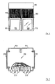
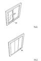
- Fig. 3 is a diagram showing a frame according to the preferred embodiment of the present invention.
- Fig. 4 is a diagram showing a connector panel provided for the frame according to the preferred embodiment of the present invention.
- Fig. 5 is a diagram showing the condition where frames are bonded together according to the preferred embodiment of the present invention.
- Fig. 6 is a diagram showing the condition where communication lines are passed between frames according to the preferred embodiment of the present invention.
- Fig. 7 is a diagram showing a frame coupling member according to the preferred embodiment of the present invention.
- Fig. 8 is a diagram showing the condition where frames are bonded together according to the preferred embodiment of the present invention.
- Fig. 9 is a diagram illustrating the condition where an external wall panel and a decorative laminated panel are attached according to the preferred embodiment of the present invention.
- Fig. 10 is a diagram illustrating the condition where an external wall panel and a decorative laminated panel are attached according to the preferred embodiment of the present invention.
- Fig. 11 is a diagram illustrating the condition where an external wall panel and a decorative laminated panel are attached according to the preferred embodiment of the present invention.
- Fig. 12 is a diagram illustrating the condition where an internal wall panel is attached according to the preferred embodiment of the present invention.
- Fig. 13 is a diagram illustrating the condition where an internal wall panel is attached according to the preferred embodiment of the present invention.
- Fig. 14 is a diagram illustrating the condition where an internal wall panel is attached according to the preferred embodiment of the present invention.
- Fig. 15 is a diagram illustrating the condition where an internal wall panel is attached according to the preferred embodiment of the present invention.
- Fig. 16 is a diagram illustrating the condition where an internal wall panel is attached according to the preferred embodiment of the present invention.
- Fig. 17 is a diagram showing one example internal wall panel according to the preferred embodiment of the present invention.
- Fig. 18 is a diagram showing another example internal wall panel according to the preferred embodiment of the present invention.
- Fig. 19 is a diagram showing an additional example internal wall panel according to the preferred embodiment of the present invention.
- Fig. 20 is a diagram showing one more example internal wall panel according to the preferred embodiment of the present invention.
- Fig. 21 is a diagram showing still another example internal wall panel according to the preferred embodiment of the present invention.
- Fig. 22 is a diagram showing a still further example internal wall panel according to the preferred embodiment of the present invention.
- Fig. 23 is a diagram showing yet another example internal wall panel according to the preferred embodiment of the present invention.
- Fig. 24 is a diagram showing another frame according to the preferred embodiment of the present invention.
- Fig. 25 is a diagram showing the extension and reconstruction of house units according to the preferred embodiment of the present invention.
- Fig. 1 is a plan view of a house unit assembly 100 according to the preferred embodiment of the present invention.
- a house unit 110 is employed as an unmanned prefabricated shop for a monetary facility, and a house unit 120 is employed as a satellite office.
- the house unit 120 are installed fixed tables 181 and 183 and chairs 191 to 197.
- tables 181 and 183 are prepared in the factory to reduce the work performed at the building site as much as possible, whereas electric devices, such as the ATM 173, the automatic loan contact machine 175 and the shredder 177, in consideration of the impact damage they could sustain during the installation of the house unit, are delivered and installed after the house unit assembly is set up.
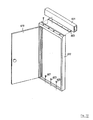
- Fig. 2 is a schematic diagram illustrating a house unit assembly according to the preferred embodiment of the present invention.
- the house unit assembly is constituted by house units 110 and 120, which are constructed on frames 111 and 113, and roof modules 190.
- the house unit 110 has an opening 121 for an entrance, and the house unit 120 has an external wall panel 163.
- a frame has a size that is appropriate for transportation by truck, i.e., about 2,400 mm wide, about 4,800 mm long and about 2,500 mm high.
- the frame 111 shown in Fig. 3 is made of stainless steel, and is constructed by welding together two rectangular frame sections and two ladder-shaped frame sections, each of which is provided by assembling two rectangular frame sections. These frame sections are formed hollow to accept electric wiring for power and communication lines of various types.
- the electric wiring and communication lines in a rectangular frame section and a ladder-shaped frame section can be connected to those in an adjacent rectangular (or ladder-shaped) frame via an opening (not shown) that is formed in a communication line corner cover 201.
- various connection terminals are exposed at the communication line corner cover 201 to facilitate their connection to the electric wiring in another frame.
- corner covers There are two kinds of corner covers: a corner cover for coupled portions and a corner cover for corners.
- a coupled portion corner cover is employed to protect the connectors for the two frames.
- a corner cover for corners is positioned at a corner of a house unit assembly to protect a communication line connection between the frame sections of the same frame. The frame is thereby protected from the entry of water, such as rain.
- the corner covers for coupled portions and for corners are so designed that they can be locked to prevent their easy removal.
- all the frame sections of the frame have hollow rectangular cross sections of 100 mm ⁇ 200 mm, and the openings (where wall panels are attached) in the square frame sections and the ladder-shaped frames all have the same dimensions of 1,800 mm ⁇ 2,100 mm.
- the internal wall panels that are used in the ladder-shaped frame sections can also be employed for the square frames.
- the opening may be so designed that it is integer times the size of the divided wall panel.
- the cross section of the frame section can be changed in accordance with the purpose for which the house unit is employed.
- the size of the cross section of the frame can be increased, and for an application that requires a smaller communication line, the size of the cross section of the frame can be reduced.
- the frame can have a curved cross section, or can be internally divided to define a plurality of spaces.
- Attached to the frames 111 and 113 are anchor portions 203, and the frames are fixed to a surface by anchor bolts that pass through the openings in the anchor portions 203.
- maintenance openings are formed at predetermined intervals in the frames 111 and 113 to facilitate the installation of communication lines that are used for connection to lines in another frame.
- Plastic maintenance opening covers 205 are mounted over the maintenance openings.
- a power source or a communication cable can be removed from the frame through a convenient maintenance opening.
- the maintenance openings can also be used to hook up cables to lift a house unit at an installation site.
- These maintenance openings may be formed not only in the beams of a frame, but also at other locations in the frame, such as in the pillars.
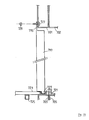
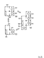
- the frame 111 and 113 have a connector panel 810 shown in Fig. 4.
- the connector panel 810 are provided power source outlets 801 and 803, coaxial cable outlets 805 and 807 and a modular telephone jack 809.
- a communication line removal opening 813 is also formed at the lower portion of the connector panel 810.
- communication cables and electric wiring enter a frame from underneath, and wiring may be laid under a floor.
- a hatch for checking beneath a floor is provided in floor material, and through this hatch, various types of connections located under the floor are connected to connections exposed on the frame.
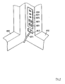
- Figs. 5 through 8 are diagrams illustrating the connection of frames and the connection of roof members.
- the frames 111 and 113 for the present invention are connected together by a bolt 251 and a nut 253. Since the connection using the bolt 251 and the nut 253 can be performed at maintenance openings, the work can proceed smoothly.
- Separate roof modules 115 are provided for the house units 111 and 113, and are individually connected to the house units 111 and 113. Therefore, when only one house unit is to be removed, the above structure obviates the need to remove the roofs of all the house units.
- C-shaped coupling members 241 are welded to the respective roof units 115, and connected thereto by using the frames and bolts.
- the roof unit 115 can be used as a frame. in this case, whether a house unit is separated from an adjacent house unit by a wall or is open can be selected in accordance with the security relative to the adjacent house unit and the air conditioning.
- a four-leg frame obtained by welding four U-shaped frames is employed.
- a communication line opening 231 to another frame may be formed, in addition to the bolt opening in Fig. 5 used to connect frames together. With this opening 231, the length of wiring can be reduced. Since the bolt opening in Fig. 5 and the communication line opening in Fig. 6 will be exposed and will permit rain water to enter a frame when it is separated from another frame, special plastic covers are used to protect the openings. According to the present invention, the maintenance covers can be locked to prevent them from falling off by accident or from being removed by an unauthorized person.
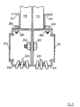
- FIG. 7 is a diagram showing a frame coupling member 250 that is used according to another example of the present invention.
- a frame coupling member 250 is formed of four flat metal plates that are connected together by hinges. Hooks 251 are formed at one end of the frame coupling member 250, and openings at which the hooks 251 are formed in the other end.
- the frame coupling member 250 is employed as is shown in Fig. 8. More specifically, after the frame coupling member 250 encloses the frames 111 and 113 and the hooks 251 engage the openings 253, to secure the frame coupling member 250, a bolt 259 is threaded into a bolt opening 255, and the flat plate of the frame coupling member 250 in which the openings 253 are formed is pushed in a direction away from the frame. In this way, the hooks 251 can be prevented from falling through the openings 253. When the frame is separated from another frame, the frame coupling member 250 can prevent the opening from being externally exposed.
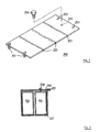
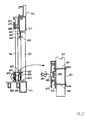
- Fig. 9 is a diagram showing the attachment of an external wall panel and a decorative laminated panel according to the preferred embodiment of the present invention.
- An external wall panel 127 and a decorative laminated panel 143 are so attached that they cover the openings in the frame.
- the bonded face of the frame is a square or a rectangular flat plane; however, the bonded face may have a curved face, so long as it can be bonded with a face of another frame.
- L-shaped stainless steel auxiliary members 403 and 415 for wall panel connection are fixed to the frame 111 by welding or by using bolts.
- Bolts 407 and 409 are embedded in the external wall panel 127.
- the external wall panel 127 is fixed to the frame 111 by using nuts 411 and 417 to secure z clips 405 and 413.
- a gap between the frame 111 and the external wall panel 127 is sealed by foamed urethane.
- a floor The structure of a floor will be explained before an explanation is given for the attachment of decorative laminated panel in one example of this embodiment.
- a plurality of reinforcement frames 441 and 443, parallel to the square frames, are welded to the floor portions of the frames 111 and 113 at predetermined intervals.
- a floor material 115 is laid on the reinforcement frames 441 and 443.
- the floor material 115 and the reinforcement frames 441 and 443 can be fastened together by using an adhesive or small screws. Since the floor is not a required component of this invention (the present invention can be implemented by installing a floor-less house unit after the installation of the floor material is completed), a detailed explanation for it will not be given.
- the decorative laminated panel 143 is so fixed to the frame 111 that, by using small screws (431 and 435), it can be secured to an auxiliary member 433 attached to the frame 111, and an auxiliary member 401 attached to the floor.
- an auxiliary member 451 attached to an auxiliary member 483 and the floor are welded to the frame 111.
- the decorative laminated panel 143 is then fixed to the frame 111 by using small screws to secure it to the auxiliary members 451 and 483.
- a coupling cover 473 and a coupling cover auxiliary member 471 are employed to maintain a fine appearance and to prevent the unauthorized removal of the decorative laminated panel and the external wall panel. Since the coupling cover 473 can be locked after being attached, the decorative laminated panel can not be removed mistakenly. Accordingly, the external wall panel can not be removed mistakenly.
- Figs. 12 and 13 are diagrams showing the condition where an internal wall panel is attached according to one example of the preferred embodiment of the present invention.
- a door panel which is one of internal wall panels, is shown.
- the door panel is arranged with the common internal walls to form a wall with a door.
- a flat auxiliary connection plate 603 is attached to a frame 601 in this example.
- a door frame 617 is secured to the auxiliary connection plate 603 by small screws.
- the door frame 617 is fixed to the floor by inserting it into a internal wall insertion groove in the floor and by securing it with small screws.
- the common internal walls are attached in the same manner, except for securing them to the floor by using small screws.
- Figs. 14 and 15 are diagrams showing the condition where an internal wall panel is attached according to another example of the preferred embodiment of the present invention.
- An auxiliary attachment member 711 is fixed to a frame 701 in advance, and a reinforcement channel 719 is fixed to a frame 703 on the floor.
- a door frame section 715 is inserted into a gap between the auxiliary attachment member 711 and the frame 701, and a door frame section 727 is inserted into the reinforcement channel 719. Then, the section 715 is secured by small screws to fix the door panel to the frame.
- the auxiliary attachment member 711 is not fixed to the frame 701 in advance, and instead is secured by small screws, the gap between the internal wall panel and the frame can be reduced.
- Fig. 16 is a diagram showing an additional example of the attachment of an internal wall panel according to the preferred embodiment of the present invention.
- a bolt 727 is embedded in a frame 701 in advance and is welded in place.
- the bolt 727 is inserted into a bolt opening in the internal wall panel section 715, and is secured by a nut 729.
- the above described method for attaching an internal wall panel can be employed for attaching an external wall panel, and the above described method for attaching an external wall panel can be used for attaching an internal wall panel.
- Coupling pieces, such as bolts, nuts and small screws, that permit wall panels (internal or external wall panels) to be easily removed are employed in the preferred embodiment of the present invention.
- locked cover for preventing the removal of coupling pieces such as are currently used for ski carriers on vehicles, are also effective for preventing unauthorized removal.
- Figs. 17 through 23 are diagrams showing various types of internal wall panels according to the preferred embodiment of the present invention. These internal wall panels are produced in a standard size. A door panel in Fig. 17 is used with an internal wall panel having the opening shown in Fig. 18. The opening in the internal wall panel corresponds to the size of the opening for a door frame.
- a glass window panel in Fig. 19 is used together with a wall opening panel in Fig. 20.
- the opening in the wall opening panel corresponds to the size of the glass window panel.
- an automatic door panel in Fig. 21, a division type internal wall panel in Fig. 22, and a shutter panel in Fig. 23 are prepared for the preferred embodiment of the present invention.
- FIG. 1 A user can employ these panels to make a desired layout of a house unit assembly.
- the opening wall panels in Fig. 20 are employed for faces 121 and 123
- the common internal wall panel in Fig. 22 is used for faces 141, 143, 145, 163, 165, 167, 168 and 169.
- a door panel in Fig. 17 is employed for a face 161
- an opening wall panel in Fig. 18 is used as a face 155.
- the external wall 127 is also divided vertically into three sections.
- a desired internal wall panel or external wall panel can be removed to perform maintenance for an ATM or an automatic contract machine, and a maintenance work area can be ensured.
- an unmanned office for a monetary facility is employed to accept customers 24 hours a day. Since workers are resident in the satellite office only during a limited time, after the satellite office is closed, gaining entry to the satellite office from the unmanned monetary facility office must be as difficult as possible. For this reason, a door 151 is so designed that it can only be unlocked by inserting a magnetic card into a magnetic card reader 153.
- a door panel is provided for the unmanned monetary facility office and a wall opening panel is provided for the satellite office, the door panel can be easily removed from the unmanned office side and unauthorized persons can easily enter the satellite office. But when a door panel is provided for the satellite office, the door panel can be removed only from the satellite office side and can not be removed from the unmanned monetary facility office side, and adequate security for the satellite office can be maintained on the unmanned office side of the monetary facility.
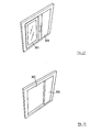
- Fig. 24 is a diagram showing a second frame according to the preferred embodiment of the present invention.
- the second frame is used together with the frame in Fig. 3. Employment examples for the second frame are shown in Fig. 25.
- a house unit assembly 500 in Fig. 25 the frame shown in Fig. 3 is used for areas 501 and 505, and the frame shown in Fig. 24 is used for areas 503 and 507.
- the areas 501 and 503 are used as CD corners and the areas 505 and 507 are used as entrance areas.
- a house unit assembly 510 having a different construction can be provided.
- a house unit assembly structured in various walls can be provided by the attachment and removal of external and internal wall panels, the installation and removal of house units, and the connection and separation of house units.
- a house unit that can be easily disassembled for moving, and for expansion and rebuilding.
- a house unit having a layout that can be easily changed.
- a house unit that can be reerected as a different construction at a location to which it is moved.
- a house unit that, in order to facilitate moving and expansion and rebuilding, requires minimum wiring.
- a house unit that provides security under any conditions, such as when it is first erected and when it is reerected.
- a house unit assembly that provides a high level of security and that can deny entry to a high security unit from a low security unit.
Landscapes
- Engineering & Computer Science (AREA)
- Architecture (AREA)
- Physics & Mathematics (AREA)
- Electromagnetism (AREA)
- Civil Engineering (AREA)
- Structural Engineering (AREA)
- Load-Bearing And Curtain Walls (AREA)
- Working Measures On Existing Buildindgs (AREA)
- Residential Or Office Buildings (AREA)
Applications Claiming Priority (2)
| Application Number | Priority Date | Filing Date | Title |
|---|---|---|---|
| JP50108/97 | 1997-03-05 | ||
| JP05010897A JP3232257B2 (ja) | 1997-03-05 | 1997-03-05 | ハウスユニット、複合ハウスユニット及び、複合ハウスユニットの改築方法 |
Publications (2)
| Publication Number | Publication Date |
|---|---|
| EP0863267A2 true EP0863267A2 (de) | 1998-09-09 |
| EP0863267A3 EP0863267A3 (de) | 1999-01-27 |
Family
ID=12849901
Family Applications (1)
| Application Number | Title | Priority Date | Filing Date |
|---|---|---|---|
| EP98301054A Withdrawn EP0863267A3 (de) | 1997-03-05 | 1998-02-13 | Hauseinheit und Rahmenkonstruktion der Hauseinheit |
Country Status (5)
| Country | Link |
|---|---|
| EP (1) | EP0863267A3 (de) |
| JP (1) | JP3232257B2 (de) |
| KR (1) | KR100247715B1 (de) |
| CN (1) | CN1111232C (de) |
| TW (1) | TW349139B (de) |
Cited By (6)
| Publication number | Priority date | Publication date | Assignee | Title |
|---|---|---|---|---|
| GB2409469A (en) * | 2003-12-15 | 2005-06-29 | Spaceover Ltd | A flat wall frame comprising perimetral frame members |
| DE102004029262A1 (de) * | 2004-06-17 | 2006-01-12 | Royal Wave Holdings Ltd., St. Helier | Haus aus modularen Bauelementen sowie Verbund aus mehreren derartigen Häusern |
| WO2006128606A1 (de) * | 2005-06-02 | 2006-12-07 | Drehtainer Gmbh Spezial Container- Und Fahrzeugbau | Aus modulen zusammensetzbares bauwerk |
| DE102011001199A1 (de) * | 2011-03-10 | 2012-09-13 | Ralf Hoge | Objekt mit einem statisch tragenden Rahmensystem |
| DE102013207392A1 (de) * | 2013-04-24 | 2014-11-13 | Harald Martin | Raumsystem |
| US11542701B2 (en) | 2018-07-10 | 2023-01-03 | Fujifilm Business Innovation Corp. | Booth |
Families Citing this family (3)
| Publication number | Priority date | Publication date | Assignee | Title |
|---|---|---|---|---|
| KR20010096360A (ko) * | 2000-04-18 | 2001-11-07 | 이수행 | 조립식의 환경친화적 및 마을공동체적인 아파트 등 빌딩형건축물의 설계 시공방법 |
| JP6367629B2 (ja) * | 2014-07-16 | 2018-08-01 | 不二サッシ株式会社 | 折り畳み式組立家屋 |
| CN105839782B (zh) * | 2016-05-13 | 2019-01-08 | 上海莫欧实业有限公司 | 模块化房屋 |
Citations (2)
| Publication number | Priority date | Publication date | Assignee | Title |
|---|---|---|---|---|
| GB2282395A (en) * | 1993-08-12 | 1995-04-05 | Optima Building Systems Intern | Building system |
| WO1996011307A1 (en) * | 1994-10-11 | 1996-04-18 | F.A.E. Industria Alloggi Prefabbricati S.P.A | Prefabricated residence block |
-
1997
- 1997-03-05 JP JP05010897A patent/JP3232257B2/ja not_active Expired - Fee Related
- 1997-09-26 TW TW086114066A patent/TW349139B/zh active
- 1997-11-19 KR KR1019970060984A patent/KR100247715B1/ko not_active IP Right Cessation
-
1998
- 1998-02-04 CN CN98103725A patent/CN1111232C/zh not_active Expired - Fee Related
- 1998-02-13 EP EP98301054A patent/EP0863267A3/de not_active Withdrawn
Patent Citations (2)
| Publication number | Priority date | Publication date | Assignee | Title |
|---|---|---|---|---|
| GB2282395A (en) * | 1993-08-12 | 1995-04-05 | Optima Building Systems Intern | Building system |
| WO1996011307A1 (en) * | 1994-10-11 | 1996-04-18 | F.A.E. Industria Alloggi Prefabbricati S.P.A | Prefabricated residence block |
Cited By (7)
| Publication number | Priority date | Publication date | Assignee | Title |
|---|---|---|---|---|
| GB2409469A (en) * | 2003-12-15 | 2005-06-29 | Spaceover Ltd | A flat wall frame comprising perimetral frame members |
| DE102004029262A1 (de) * | 2004-06-17 | 2006-01-12 | Royal Wave Holdings Ltd., St. Helier | Haus aus modularen Bauelementen sowie Verbund aus mehreren derartigen Häusern |
| WO2006128606A1 (de) * | 2005-06-02 | 2006-12-07 | Drehtainer Gmbh Spezial Container- Und Fahrzeugbau | Aus modulen zusammensetzbares bauwerk |
| DE102011001199A1 (de) * | 2011-03-10 | 2012-09-13 | Ralf Hoge | Objekt mit einem statisch tragenden Rahmensystem |
| DE102011001199B4 (de) * | 2011-03-10 | 2014-05-28 | Ralf Hoge | Objekt mit einem statisch tragenden Rahmensystem |
| DE102013207392A1 (de) * | 2013-04-24 | 2014-11-13 | Harald Martin | Raumsystem |
| US11542701B2 (en) | 2018-07-10 | 2023-01-03 | Fujifilm Business Innovation Corp. | Booth |
Also Published As
| Publication number | Publication date |
|---|---|
| TW349139B (en) | 1999-01-01 |
| EP0863267A3 (de) | 1999-01-27 |
| JPH10245891A (ja) | 1998-09-14 |
| KR100247715B1 (ko) | 2000-03-15 |
| KR19980079472A (ko) | 1998-11-25 |
| JP3232257B2 (ja) | 2001-11-26 |
| CN1195733A (zh) | 1998-10-14 |
| CN1111232C (zh) | 2003-06-11 |
Similar Documents
| Publication | Publication Date | Title |
|---|---|---|
| US9765510B2 (en) | Structural wall panels for use in light-frame construction and methods of construction employing structural wall panels | |
| US5813174A (en) | Closet vault | |
| US4255912A (en) | Temporary shelter | |
| AU1737600A (en) | Container for prefabricated transportable buildings | |
| EP0863267A2 (de) | Hauseinheit und Rahmenkonstruktion der Hauseinheit | |
| EP3618598B1 (de) | Heiss/kalt-regal-system | |
| US3832605A (en) | Prefabricated housing for electrical switchgear with external housing wall attachment means | |
| US6349510B1 (en) | Equipment shelter facilities | |
| US5613331A (en) | Modular oil change and lubrication center for vehicles | |
| JP2843016B2 (ja) | 折畳み式階段ユニットボックスおよびこれを用いた建物 | |
| KR101086059B1 (ko) | 조립식 건축용 모듈의 체결구조 | |
| EP0929726B1 (de) | Unterkunft für unterschiedliche bewohner | |
| JP2618567B2 (ja) | ユニット建物の施工方法 | |
| JP2771969B2 (ja) | ガレージ用建物ユニット | |
| KR102344569B1 (ko) | 실내에서 체결 가능한 프레임 체결 구조 | |
| JP3401652B2 (ja) | エレベータ用乗り込みステージ | |
| JPH0734547A (ja) | ユニット式建物 | |
| EP3614818A1 (de) | Heiss/kalt-regal-system | |
| JP2771970B2 (ja) | ガレージ付きユニット建物 | |
| JP2771971B2 (ja) | ガレージ付きユニット建物 | |
| JPH07102641A (ja) | ユニット式建物における付属ユニットの取付け構造 | |
| JP3486442B2 (ja) | 開口部上部の補強構造 | |
| AU2020233676A1 (en) | Fire Booster Cabinet & Method | |
| WO2024023342A1 (en) | Modular building unit, building system, building and associated methods | |
| JPH02131306A (ja) | 電気設備 |
Legal Events
| Date | Code | Title | Description |
|---|---|---|---|
| PUAI | Public reference made under article 153(3) epc to a published international application that has entered the european phase |
Free format text: ORIGINAL CODE: 0009012 |
|
| AK | Designated contracting states |
Kind code of ref document: A2 Designated state(s): DE FR GB IT |
|
| AX | Request for extension of the european patent |
Free format text: AL;LT;LV;MK;RO;SI |
|
| PUAL | Search report despatched |
Free format text: ORIGINAL CODE: 0009013 |
|
| AK | Designated contracting states |
Kind code of ref document: A3 Designated state(s): AT BE CH DE DK ES FI FR GB GR IE IT LI LU MC NL PT SE |
|
| AX | Request for extension of the european patent |
Free format text: AL;LT;LV;MK;RO;SI |
|
| 17P | Request for examination filed |
Effective date: 19990518 |
|
| AKX | Designation fees paid |
Free format text: DE FR GB IT |
|
| 17Q | First examination report despatched |
Effective date: 20000207 |
|
| STAA | Information on the status of an ep patent application or granted ep patent |
Free format text: STATUS: THE APPLICATION HAS BEEN WITHDRAWN |
|
| 18W | Application withdrawn |
Withdrawal date: 20001206 |