EP0862850B1 - Mähdrescher - Google Patents
Mähdrescher Download PDFInfo
- Publication number
- EP0862850B1 EP0862850B1 EP98103561A EP98103561A EP0862850B1 EP 0862850 B1 EP0862850 B1 EP 0862850B1 EP 98103561 A EP98103561 A EP 98103561A EP 98103561 A EP98103561 A EP 98103561A EP 0862850 B1 EP0862850 B1 EP 0862850B1
- Authority
- EP
- European Patent Office
- Prior art keywords
- rotors
- straw
- combine according
- rotor
- combine
- Prior art date
- Legal status (The legal status is an assumption and is not a legal conclusion. Google has not performed a legal analysis and makes no representation as to the accuracy of the status listed.)
- Expired - Lifetime
Links
- 239000010902 straw Substances 0.000 claims description 45
- 241001272996 Polyphylla fullo Species 0.000 claims description 19
- 230000033001 locomotion Effects 0.000 description 7
- 238000000926 separation method Methods 0.000 description 7
- 206010010774 Constipation Diseases 0.000 description 2
- 230000001133 acceleration Effects 0.000 description 2
- 230000008021 deposition Effects 0.000 description 2
- 230000000694 effects Effects 0.000 description 2
- 239000000463 material Substances 0.000 description 2
- 239000000203 mixture Substances 0.000 description 2
- 230000001737 promoting effect Effects 0.000 description 2
- 241000251169 Alopias vulpinus Species 0.000 description 1
- 240000002791 Brassica napus Species 0.000 description 1
- 235000004977 Brassica sinapistrum Nutrition 0.000 description 1
- 241000196324 Embryophyta Species 0.000 description 1
- 241001124569 Lycaenidae Species 0.000 description 1
- 229910000639 Spring steel Inorganic materials 0.000 description 1
- 240000008042 Zea mays Species 0.000 description 1
- 235000005824 Zea mays ssp. parviglumis Nutrition 0.000 description 1
- 235000002017 Zea mays subsp mays Nutrition 0.000 description 1
- 230000005540 biological transmission Effects 0.000 description 1
- 230000015572 biosynthetic process Effects 0.000 description 1
- 239000000969 carrier Substances 0.000 description 1
- 235000005822 corn Nutrition 0.000 description 1
- 238000003306 harvesting Methods 0.000 description 1
- 230000000149 penetrating effect Effects 0.000 description 1
- 238000011084 recovery Methods 0.000 description 1
- 239000004575 stone Substances 0.000 description 1
- 239000006228 supernatant Substances 0.000 description 1
- 230000007704 transition Effects 0.000 description 1
- 238000011144 upstream manufacturing Methods 0.000 description 1
Images

Classifications
-
- A—HUMAN NECESSITIES
- A01—AGRICULTURE; FORESTRY; ANIMAL HUSBANDRY; HUNTING; TRAPPING; FISHING
- A01F—PROCESSING OF HARVESTED PRODUCE; HAY OR STRAW PRESSES; DEVICES FOR STORING AGRICULTURAL OR HORTICULTURAL PRODUCE
- A01F12/00—Parts or details of threshing apparatus
- A01F12/30—Straw separators, i.e. straw walkers, for separating residual grain from the straw
- A01F12/305—Straw separators, i.e. straw walkers, for separating residual grain from the straw combined with additional grain extracting means
-
- Y—GENERAL TAGGING OF NEW TECHNOLOGICAL DEVELOPMENTS; GENERAL TAGGING OF CROSS-SECTIONAL TECHNOLOGIES SPANNING OVER SEVERAL SECTIONS OF THE IPC; TECHNICAL SUBJECTS COVERED BY FORMER USPC CROSS-REFERENCE ART COLLECTIONS [XRACs] AND DIGESTS
- Y10—TECHNICAL SUBJECTS COVERED BY FORMER USPC
- Y10S—TECHNICAL SUBJECTS COVERED BY FORMER USPC CROSS-REFERENCE ART COLLECTIONS [XRACs] AND DIGESTS
- Y10S460/00—Crop threshing or separating
- Y10S460/901—Material distributor
Definitions
- the invention relates to a combine harvester with straw walkers and a rotary separator provided above the straw walkers.
- DE-OS-1 904 406 discloses a combine with one subtly promoting tine rotor above Straw walkers.
- This tine rotor consists of one Rotor housing, an eccentrically mounted shaft and on the shaft rotatably mounted and through the wall of the Rotor housing extending tines together.
- the tines are either over swash plates attached to the shaft, or the shaft is secured by means of a Eccentric motor constantly moved axially. Move this way the free tine ends in the axial direction of the Rotors and tear the straw mat further apart.
- a combine harvester emerges, in the Area between straw walkers and a straw hood Pick-up-like overhead conveyor is located.
- This overhead conveyor picks up the straw walker in a front area Straw on and gives it back behind. In the one below the short straw can be separated.
- the overhead conveyor can also be connected to a shaker be provided.
- a similar device is also from the FR-PS-1,473,891 and DE-AS-2 103 981 known, the device there also in a non-operating position can be brought.
- GB-PS-698,324 is above a straw walker also an overhead conveyor is provided, which consists of a Drum and toothed racks aligned on it consists.
- DE-OS-2 431 588 teaches an additional separator in Delivery area of the threshing device of a combine harvester tines movable or resiliently mounted on a rotor which undermine the crop.
- the tines are compliant, but always extend with her full length in the crop. It is also suggested to provide several such additional separators in a row.
- an overhead is promoting Separation drum between a threshing device and Straw walkers inserted that from the threshing device catches and brakes coming threshed good, so that in the Grain contained grains on the surface of the Separator drum come to rest while the straw is on the Straw shaker is passed on.
- DE-A1-41 27 118 shows a combine harvester Straw walkers and one above these so-called cross shaker, which is the crop subtly encourages.
- a carrier tape also used to promote that tears open the mat and into the Gap between the cross walker and the straw walker interjects.
- Counter-rotating rotors are of advantage where there is a high impact on the Good batch is required and / or it depends on the straw quality does not arrive. This arrangement also leads to a safe one Plant the straw on the straw walkers, which z. B. with rapeseed or long straw to avoid blockages.
- a change in distance between the rotors and the Straw shakers can help the rotor e.g. B. when threshing Decommissioning corn or reducing the degree of impact of Adapt the driver to what is required.
- a rotor conveying faster than the straw walkers causes that the straw mat he took thinned and thus becomes more separation-friendly.
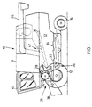
- a combine 10 shown in Figure 1 is on the front driven and rear steerable wheels 12 and 14, respectively worn and has a driver's cab 16 from which it can be operated by a driver.
- a combine could also be a stationary thresher, a trial threshing system or the like come into question.
- a grain tank closes to the rear of the driver's cab 16 18 to the goods delivered into it via an emptying pipe 20 can give up outside.
- the grain tank 18 is supported on a frame 22, in the supplied material on the way via a threshing drum 24, a concave 26 and a turning drum 28 in his large and small components is disassembled.
- the rotary separator 42 is provided to the on Straw shakers 30 brought up from the threshing device 25 Loosen the crop mixture so that it is contained in it Grains through the separation openings, not shown, in the Escape the shaker pads and reach the sieves 34 can.
- the rotary separator 42 at least contains two in a row, d. H. connected in series Rotors 44, whose distance is chosen so that the upstream rotor 44 'leaving crop from the downstream rotor 44 '' can be detected.
- Each rotor 44 consists of a rotor housing 46, one therein eccentrically mounted shaft 48 and rotatable on the shaft 48 attached driver 50 in the form of rigid fingers or resilient tines.
- Each rotor housing 46 is with the shaft 48 and the drivers 50 like a conventional drum conveyor, e.g. B. in the middle of one Feed auger of a cutting unit or a pick-up designed so that there is no detailed description can be.
- a conventional drum conveyor e.g. B. in the middle of one Feed auger of a cutting unit or a pick-up designed so that there is no detailed description can be.
- the rotor housing 46 is designed as a tube that over its entire length and in various circumferential distributed rows with outlet openings for the carriers 50 is provided.
- the rotor housing 46 is on both sides in the Side walls of the frame 22 rotatably supported and by driven at least one side.
- each rotor 44 i.e. H. whose Rotor housing 46 by means of a corresponding not shown gear, z. B. a belt transmission and / or a planetary gear.
- the shaft 48 is also mounted in the frame 22 and extends in the direction of the longitudinal central axis of the Rotor housing 46 but parallel to this. If that too relative position of the shaft 48 basically during operation is unchangeable, it can change the aggressiveness of the Driver 50 a change in position of the shaft 48 but in principle be made.
- the shaft 48 can be known Way stored on levers or the like and around one Pivot point are moved so that the distance to all Exit points of the drivers 50 from the rotor housing 46 changed.
- the drivers 50 are straight and consist of Spring steel so that the rotors 44 in both directions can be operated. Should the rotors 44 only in each case the drivers 50 can also be operated in one direction be trailing curved. Known and therefore not shown, the drivers 50 are on by means of bearings the shaft 48 rotatably mounted within the rotor housing 46 and move during the rotation of the rotor housing 46 in essentially radially through the wall between two End positions.
- FIGS. 2 to 4 shows the rotors 44 driven in different directions. Because everyone Direction of rotation a certain and different position of the driver 50 requires, there is a change in every direction of rotation of the field of motion of the drivers 50, like this is shown.
- a guide device is located above the rotary separator 42 52 provided for a continuous flow of Harvest crops.
- This guide device 52 can be both a sheet, at least a smooth surface as well curved drivers exist, one in the drawing occupy the shape shown, the movement of the Carrier 50 follows.
- the straw walkers 30 are in their area below the Rotary separator 42 advantageously, if not necessary, also to the movement field of the driver 50 or adjusted the expected flow of crop. This is at the 2, in which both rotors 44 promote underdelivery, on the straw walkers 30 none Steep step arranged, rather the straw walkers run 30 flat in this area. As in the rest of the area Straw shaker 30 also below the rotary separator 42 provided with permeable shaker coverings.
- Elevation 54 is provided, which is hump-shaped and yourself in the gusset area between two movement fields of the Driver 50 extends into it. Since the straw walker 30 a execute oscillating movement, it is not possible to Fill the gusset area completely with an elevation 54.
- FIG. 3 shows a version in which both rotors 44 superlative, d. H. Promote overhead.
- the vertical movement of the threshed material is downward from the rotor housings 46 and limited by the guide device 52.
- the lower gusset area extends the elevation 54, the also ensures that no goods are returned.
- the crop mat from the front rotor 44 'to rear rotor 44' ' passed, passing the gap between these and Let the grains fall out downwards.
- the formation and arrangement of the guide device 52 and the Elevation 54 are in the exemplary embodiments of FIGS. 3 and 4 equal.
Landscapes
- Life Sciences & Earth Sciences (AREA)
- Environmental Sciences (AREA)
- Harvesting Machines For Root Crops (AREA)
- Outside Dividers And Delivering Mechanisms For Harvesters (AREA)
Applications Claiming Priority (2)
| Application Number | Priority Date | Filing Date | Title |
|---|---|---|---|
| DE19709396 | 1997-03-07 | ||
| DE19709396A DE19709396A1 (de) | 1997-03-07 | 1997-03-07 | Mähdrescher |
Publications (2)
| Publication Number | Publication Date |
|---|---|
| EP0862850A1 EP0862850A1 (de) | 1998-09-09 |
| EP0862850B1 true EP0862850B1 (de) | 2003-05-07 |
Family
ID=7822583
Family Applications (1)
| Application Number | Title | Priority Date | Filing Date |
|---|---|---|---|
| EP98103561A Expired - Lifetime EP0862850B1 (de) | 1997-03-07 | 1998-02-28 | Mähdrescher |
Country Status (4)
| Country | Link |
|---|---|
| US (1) | US6190253B1 (da) |
| EP (1) | EP0862850B1 (da) |
| DE (2) | DE19709396A1 (da) |
| DK (1) | DK0862850T3 (da) |
Families Citing this family (8)
| Publication number | Priority date | Publication date | Assignee | Title |
|---|---|---|---|---|
| DE19920538A1 (de) * | 1999-05-05 | 2000-11-09 | Claas Selbstfahr Erntemasch | Erntemaschine |
| US6672957B2 (en) * | 2002-03-28 | 2004-01-06 | Agco Corporation | Combine harvester cleaning apparatus |
| DE102004013255B4 (de) * | 2004-03-18 | 2012-03-08 | Deere & Company | Mähdrescher mit einem Rotationsförderer |
| DE102004031054A1 (de) * | 2004-06-25 | 2006-01-19 | Claas Selbstfahrende Erntemaschinen Gmbh | Schüttlerhilfe an einem Mähdrescher |
| DE102007005173B4 (de) * | 2007-01-29 | 2014-02-27 | Claas Selbstfahrende Erntemaschinen Gmbh | Mähdrescher sowie Verfahren zum Häckseln von Stroh in einem Mähdrescher |
| DE102007009313A1 (de) * | 2007-02-22 | 2008-08-28 | Claas Selbstfahrende Erntemaschinen Gmbh | Landwirtschaftliche Arbeitsmaschine |
| GB201207827D0 (en) * | 2012-05-04 | 2012-06-13 | Laverda Spa | Combine harvester with a transverse separating system |
| EP3876695B1 (en) * | 2018-11-06 | 2023-09-13 | Jakob Sørensen IP Aps | A grain separating apparatus for a combine harvester and a method for separating grain from straw material |
Family Cites Families (31)
| Publication number | Priority date | Publication date | Assignee | Title |
|---|---|---|---|---|
| US249055A (en) * | 1881-11-01 | Grain-separator | ||
| US833700A (en) * | 1904-05-26 | 1906-10-16 | David Still | Threshing-machine. |
| US1263233A (en) * | 1916-09-29 | 1918-04-16 | Paul Habeck | Threshing-machine. |
| US1547476A (en) * | 1922-04-10 | 1925-07-28 | White Arthur William | Separating device for thrashing machines |
| US2150856A (en) * | 1935-06-20 | 1939-03-14 | Williams Richard | Threshing machine |
| GB698324A (en) | 1950-02-06 | 1953-10-14 | Thomas John Perry | Improvements in or relating to harvesters |
| US2670845A (en) * | 1950-06-30 | 1954-03-02 | Leonard W H Busack | Grain separating process and apparatus |
| US2950720A (en) * | 1957-01-14 | 1960-08-30 | Marville F Sheard | Grain separator |
| GB1107551A (en) * | 1964-03-03 | 1968-03-27 | Massey Ferguson Perkins Ltd | Improvements in combine harvester rear beaters |
| FR1473891A (fr) | 1965-10-07 | 1967-03-24 | Système de secouage rotatif pour moissonneuses-batteuse | |
| US3494115A (en) * | 1966-09-01 | 1970-02-10 | Massey Ferguson Ind Ltd | Vibrational grain separating apparatus for agricultural combines |
| US3411615A (en) | 1967-01-30 | 1968-11-19 | Sperry Rand Corp | Bracket for retractable finger crop feeding drum |
| NL6903708A (da) * | 1969-03-11 | 1970-09-15 | ||
| US3593719A (en) * | 1969-04-02 | 1971-07-20 | Massey Ferguson Ind Ltd | Combine with three-stage separation |
| DE2001386C3 (de) * | 1970-01-14 | 1974-02-14 | Deere & Company, Moline, Ill. (V.St.A.) | Vorrichtung zum Verteilen und Lockern des aus der Dreschvorrichtung eines Mähdreschers anfallenden Gutes |
| DE2103981B2 (de) | 1971-01-28 | 1974-02-28 | Deere & Co., Moline, Ill. (V.St.A.) | Oberhalb des Strohschüttlers von Dreschmaschinen und Mähdreschern angeordnete Vorrichtung zur Intensivierung der Restkörnerausscheidung |
| DE2235061C3 (de) * | 1972-07-17 | 1978-07-13 | Deere & Co., Moline, Ill. (V.St.A.), Niederlassung Deere & Co. European Office, 6800 Mannheim | Oberhalb des Hordenschüttlers von Mähdreschern angeordnete Umleitvorrichtung |
| DE2419268A1 (de) | 1974-04-22 | 1975-11-06 | Fahr Ag Maschf | Vorrichtung zur koernerabscheidung bei dreschmaschinen, insbesondere maehdrescher |
| DE2431588A1 (de) | 1974-07-01 | 1976-02-05 | Fahr Ag Maschf | Auflockerungsvorrichtung oberhalb eines strohschuettlers einer dreschmaschine |
| DE2512150A1 (de) * | 1975-03-20 | 1976-10-07 | Fahr Ag Maschf | Maehdrescher mit einer den dreschorganen nachgeschalteten vorrichtung zum trennen von koernern aus halm- und/oder blattfoermigem gut |
| FR2342022A1 (fr) * | 1976-02-24 | 1977-09-23 | Duris Sa Ets C | Dispositif recuperateur de grain dans une machine moissonneuse-batteuse |
| SU664608A1 (ru) * | 1978-01-06 | 1979-05-30 | Уральский Научно-Исследовательский Институт Сельского Хозяйства | Молотильно-сепарирующее устройство |
| DD158460A3 (de) * | 1981-04-02 | 1983-01-19 | Johann Rumpler | Lockerungs-und verteilvorrichtung an strohschuettlern |
| DE3621995A1 (de) | 1986-07-01 | 1988-01-14 | Welger Geb | Aufsammler fuer halmguterntemaschinen |
| SU1664167A1 (ru) * | 1988-12-05 | 1991-07-23 | Московский институт инженеров сельскохозяйственного производства им.В.П.Горячкина | Сепаратор грубого вороха |
| US4959038A (en) * | 1989-06-30 | 1990-09-25 | Natural Fibers Corp. | Milkweed processing machine |
| US5021029A (en) * | 1989-11-01 | 1991-06-04 | Cliff Usick | Grain saver attachment for the straw walker of a combine |
| DE4127118A1 (de) | 1991-08-16 | 1993-02-25 | Deere & Co | Abscheidevorrichtung |
| DE4209020C3 (de) * | 1992-03-20 | 1996-04-25 | Deere & Co | Trennvorrichtung |
| DE4225551C2 (de) * | 1992-08-03 | 1994-07-28 | Deere & Co | Rotationsförderer und Abscheidevorrichtung |
| US5487703A (en) * | 1994-02-08 | 1996-01-30 | Kuchar; George J. | Straw walker for chaff removal in a combine |
-
1997
- 1997-03-07 DE DE19709396A patent/DE19709396A1/de not_active Withdrawn
-
1998
- 1998-02-28 DK DK98103561T patent/DK0862850T3/da active
- 1998-02-28 DE DE59808209T patent/DE59808209D1/de not_active Expired - Fee Related
- 1998-02-28 EP EP98103561A patent/EP0862850B1/de not_active Expired - Lifetime
- 1998-03-02 US US09/033,355 patent/US6190253B1/en not_active Expired - Fee Related
Also Published As
| Publication number | Publication date |
|---|---|
| DE59808209D1 (de) | 2003-06-12 |
| US6190253B1 (en) | 2001-02-20 |
| DK0862850T3 (da) | 2003-08-25 |
| DE19709396A1 (de) | 1998-09-10 |
| EP0862850A1 (de) | 1998-09-09 |
Similar Documents
| Publication | Publication Date | Title |
|---|---|---|
| DE2729033C2 (da) | ||
| DE2462568C2 (de) | Mähdrescher | |
| DE2245602C2 (de) | Zwischen Mäh- und Dreschwerk eines Mähdreschers angeordnete Zuführungseinrichtung für Erntegut | |
| DE2729012C2 (de) | Mähdrescher der Axialflußbauart | |
| DE2628414A1 (de) | Dreschmaschine, insbesondere maehdrescher | |
| DE2433948A1 (de) | Ernte- und dreschmaschine | |
| DE4127117A1 (de) | Foerdersystem | |
| DE102013226436B4 (de) | Schrägförderer für einen Mähdrescher | |
| DE3042736C2 (da) | ||
| DE2917416A1 (de) | Axial durchstroemte trenneinheit fuer maehdrescher | |
| DE3025380C2 (da) | ||
| EP0862850B1 (de) | Mähdrescher | |
| EP2036425B2 (de) | Dreschkorbanordnung für einen Mähdrescher | |
| DE10314081B4 (de) | Austrageinrichtung zum Austragen von Erntegut aus einer Erntemaschine | |
| DE1222307B (de) | Dresch- und Trennvorrichtung | |
| DE2413975C2 (de) | Kornabschneider, z.B. für Mähdrescher | |
| EP0862849B1 (de) | Gutbearbeitungsvorrichtung | |
| DE2503693A1 (de) | Kornabscheidevorrichtung fuer einen maehdrescher | |
| DE102007010933A1 (de) | Vorrichtung und Verfahren zum Dreschen von kornhaltigem Erntegut, insbesondere von Hanf | |
| DE3325951A1 (de) | Selbstfahrender maehdrescher | |
| DE1301602B (de) | Vorrichtung in einem Maehdrescher zum Nachdreschen und Foerdern von gedroschenem Erntegut und zum gleichzeitigen Trennen der Koerner vom Stroh | |
| EP0862848A1 (de) | Mähdrescher | |
| DE3209334A1 (de) | Anbaugeraet fuer erntemaschinen zum einzug von erntegut | |
| EP1864566B1 (de) | Mähdrescher mit einer Körner abscheidenden Fördereinrichtung zwischen der Reinigungseinrichtung und einem Abgabeförderer für Spreu | |
| DE1582621B1 (de) | Vorrichtung zum Sortieren von Erntegutbestandteilen,insbesondere fuer Maehdrescher |
Legal Events
| Date | Code | Title | Description |
|---|---|---|---|
| PUAI | Public reference made under article 153(3) epc to a published international application that has entered the european phase |
Free format text: ORIGINAL CODE: 0009012 |
|
| AK | Designated contracting states |
Kind code of ref document: A1 Designated state(s): BE DE DK FI FR GB IT |
|
| AX | Request for extension of the european patent |
Free format text: AL;LT;LV;MK;RO;SI |
|
| 17P | Request for examination filed |
Effective date: 19990304 |
|
| AKX | Designation fees paid |
Free format text: BE DE DK FI FR GB IT |
|
| RBV | Designated contracting states (corrected) |
Designated state(s): BE DE DK FI FR GB IT |
|
| 17Q | First examination report despatched |
Effective date: 20020326 |
|
| GRAH | Despatch of communication of intention to grant a patent |
Free format text: ORIGINAL CODE: EPIDOS IGRA |
|
| GRAH | Despatch of communication of intention to grant a patent |
Free format text: ORIGINAL CODE: EPIDOS IGRA |
|
| GRAA | (expected) grant |
Free format text: ORIGINAL CODE: 0009210 |
|
| AK | Designated contracting states |
Designated state(s): BE DE DK FI FR GB IT |
|
| PG25 | Lapsed in a contracting state [announced via postgrant information from national office to epo] |
Ref country code: IT Free format text: LAPSE BECAUSE OF FAILURE TO SUBMIT A TRANSLATION OF THE DESCRIPTION OR TO PAY THE FEE WITHIN THE PRESCRIBED TIME-LIMIT;WARNING: LAPSES OF ITALIAN PATENTS WITH EFFECTIVE DATE BEFORE 2007 MAY HAVE OCCURRED AT ANY TIME BEFORE 2007. THE CORRECT EFFECTIVE DATE MAY BE DIFFERENT FROM THE ONE RECORDED. Effective date: 20030507 Ref country code: GB Free format text: LAPSE BECAUSE OF FAILURE TO SUBMIT A TRANSLATION OF THE DESCRIPTION OR TO PAY THE FEE WITHIN THE PRESCRIBED TIME-LIMIT Effective date: 20030507 Ref country code: FR Free format text: LAPSE BECAUSE OF FAILURE TO SUBMIT A TRANSLATION OF THE DESCRIPTION OR TO PAY THE FEE WITHIN THE PRESCRIBED TIME-LIMIT Effective date: 20030507 Ref country code: FI Free format text: LAPSE BECAUSE OF FAILURE TO SUBMIT A TRANSLATION OF THE DESCRIPTION OR TO PAY THE FEE WITHIN THE PRESCRIBED TIME-LIMIT Effective date: 20030507 |
|
| REG | Reference to a national code |
Ref country code: GB Ref legal event code: FG4D Free format text: NOT ENGLISH |
|
| REF | Corresponds to: |
Ref document number: 59808209 Country of ref document: DE Date of ref document: 20030612 Kind code of ref document: P |
|
| REG | Reference to a national code |
Ref country code: DK Ref legal event code: T3 |
|
| GBV | Gb: ep patent (uk) treated as always having been void in accordance with gb section 77(7)/1977 [no translation filed] |
Effective date: 20030507 |
|
| PGFP | Annual fee paid to national office [announced via postgrant information from national office to epo] |
Ref country code: DK Payment date: 20040123 Year of fee payment: 7 |
|
| PLBE | No opposition filed within time limit |
Free format text: ORIGINAL CODE: 0009261 |
|
| STAA | Information on the status of an ep patent application or granted ep patent |
Free format text: STATUS: NO OPPOSITION FILED WITHIN TIME LIMIT |
|
| PGFP | Annual fee paid to national office [announced via postgrant information from national office to epo] |
Ref country code: BE Payment date: 20040323 Year of fee payment: 7 |
|
| 26N | No opposition filed |
Effective date: 20040210 |
|
| EN | Fr: translation not filed | ||
| PG25 | Lapsed in a contracting state [announced via postgrant information from national office to epo] |
Ref country code: DK Free format text: LAPSE BECAUSE OF NON-PAYMENT OF DUE FEES Effective date: 20050228 Ref country code: BE Free format text: LAPSE BECAUSE OF NON-PAYMENT OF DUE FEES Effective date: 20050228 |
|
| BERE | Be: lapsed |
Owner name: *DEERE & CY Effective date: 20050228 |
|
| REG | Reference to a national code |
Ref country code: DK Ref legal event code: EBP |
|
| PGFP | Annual fee paid to national office [announced via postgrant information from national office to epo] |
Ref country code: DE Payment date: 20060119 Year of fee payment: 9 |
|
| BERE | Be: lapsed |
Owner name: *DEERE & CY Effective date: 20050228 |
|
| PG25 | Lapsed in a contracting state [announced via postgrant information from national office to epo] |
Ref country code: DE Free format text: LAPSE BECAUSE OF NON-PAYMENT OF DUE FEES Effective date: 20070901 |