EP0862080B1 - Bildaufnahme- und Bildwiedergabegerät - Google Patents
Bildaufnahme- und Bildwiedergabegerät Download PDFInfo
- Publication number
- EP0862080B1 EP0862080B1 EP98103382A EP98103382A EP0862080B1 EP 0862080 B1 EP0862080 B1 EP 0862080B1 EP 98103382 A EP98103382 A EP 98103382A EP 98103382 A EP98103382 A EP 98103382A EP 0862080 B1 EP0862080 B1 EP 0862080B1
- Authority
- EP
- European Patent Office
- Prior art keywords
- output terminal
- signal output
- detection sensor
- image
- switch
- Prior art date
- Legal status (The legal status is an assumption and is not a legal conclusion. Google has not performed a legal analysis and makes no representation as to the accuracy of the status listed.)
- Expired - Lifetime
Links
- 238000012545 processing Methods 0.000 claims description 24
- 238000001454 recorded image Methods 0.000 claims description 4
- 238000001514 detection method Methods 0.000 claims 27
- 238000010586 diagram Methods 0.000 description 5
- 230000006835 compression Effects 0.000 description 3
- 238000007906 compression Methods 0.000 description 3
- 238000012937 correction Methods 0.000 description 2
- 230000006870 function Effects 0.000 description 2
- 239000004973 liquid crystal related substance Substances 0.000 description 2
- 230000001419 dependent effect Effects 0.000 description 1
- 238000011161 development Methods 0.000 description 1
- 230000018109 developmental process Effects 0.000 description 1
- 230000000694 effects Effects 0.000 description 1
- 238000000034 method Methods 0.000 description 1
- 230000004044 response Effects 0.000 description 1
- 238000000926 separation method Methods 0.000 description 1
- 238000012546 transfer Methods 0.000 description 1
Images


Classifications
-
- H—ELECTRICITY
- H04—ELECTRIC COMMUNICATION TECHNIQUE
- H04N—PICTORIAL COMMUNICATION, e.g. TELEVISION
- H04N5/00—Details of television systems
- H04N5/76—Television signal recording
- H04N5/765—Interface circuits between an apparatus for recording and another apparatus
-
- H—ELECTRICITY
- H04—ELECTRIC COMMUNICATION TECHNIQUE
- H04N—PICTORIAL COMMUNICATION, e.g. TELEVISION
- H04N23/00—Cameras or camera modules comprising electronic image sensors; Control thereof
- H04N23/60—Control of cameras or camera modules
- H04N23/65—Control of camera operation in relation to power supply
- H04N23/651—Control of camera operation in relation to power supply for reducing power consumption by affecting camera operations, e.g. sleep mode, hibernation mode or power off of selective parts of the camera
-
- H—ELECTRICITY
- H04—ELECTRIC COMMUNICATION TECHNIQUE
- H04N—PICTORIAL COMMUNICATION, e.g. TELEVISION
- H04N23/00—Cameras or camera modules comprising electronic image sensors; Control thereof
- H04N23/60—Control of cameras or camera modules
- H04N23/63—Control of cameras or camera modules by using electronic viewfinders
-
- H—ELECTRICITY
- H04—ELECTRIC COMMUNICATION TECHNIQUE
- H04N—PICTORIAL COMMUNICATION, e.g. TELEVISION
- H04N5/00—Details of television systems
- H04N5/76—Television signal recording
- H04N5/765—Interface circuits between an apparatus for recording and another apparatus
- H04N5/77—Interface circuits between an apparatus for recording and another apparatus between a recording apparatus and a television camera
- H04N5/772—Interface circuits between an apparatus for recording and another apparatus between a recording apparatus and a television camera the recording apparatus and the television camera being placed in the same enclosure
-
- G—PHYSICS
- G03—PHOTOGRAPHY; CINEMATOGRAPHY; ANALOGOUS TECHNIQUES USING WAVES OTHER THAN OPTICAL WAVES; ELECTROGRAPHY; HOLOGRAPHY
- G03B—APPARATUS OR ARRANGEMENTS FOR TAKING PHOTOGRAPHS OR FOR PROJECTING OR VIEWING THEM; APPARATUS OR ARRANGEMENTS EMPLOYING ANALOGOUS TECHNIQUES USING WAVES OTHER THAN OPTICAL WAVES; ACCESSORIES THEREFOR
- G03B13/00—Viewfinders; Focusing aids for cameras; Means for focusing for cameras; Autofocus systems for cameras
- G03B13/02—Viewfinders
-
- G—PHYSICS
- G03—PHOTOGRAPHY; CINEMATOGRAPHY; ANALOGOUS TECHNIQUES USING WAVES OTHER THAN OPTICAL WAVES; ELECTROGRAPHY; HOLOGRAPHY
- G03B—APPARATUS OR ARRANGEMENTS FOR TAKING PHOTOGRAPHS OR FOR PROJECTING OR VIEWING THEM; APPARATUS OR ARRANGEMENTS EMPLOYING ANALOGOUS TECHNIQUES USING WAVES OTHER THAN OPTICAL WAVES; ACCESSORIES THEREFOR
- G03B2217/00—Details of cameras or camera bodies; Accessories therefor
- G03B2217/007—Details of energy supply or management
Definitions
- the present invention relates to an image recording and reproducing apparatus. More specifically, the present invention relates to an image recording and reproducing apparatus having an image pickup mode for picking up and recording an image, and a reproduction mode for reproducing the recorded image.
- Fig. 4 is a block diagram showing a structure of a conventional digital still camera 10.
- digital still camera 10 includes a mode switch 11, an LCD switch 12, a shutter switch 13, a lens cover switch 14 and a system controller 15. Further, digital still camera 10 includes a lens 21, a CCD (Charge Coupled Device) 22, an A/D converter 23, a signal processing circuit 24, a CPU 25, a flash memory 26, a selector 27, a VRAM 28, a liquid crystal display (LCD) 29, a D/A converter 30, a digital signal input/output terminal 31 and an analog signal output terminal 32.
- CCD Charge Coupled Device
- Mode switch 11 is for switching between the image pickup mode for picking up and recording an image, and a reproduction mode for reproducing the recorded image.
- LCD switch 12 is for turning on or off power supply to LCD 29 so as to set LCD 29 to a display enabled state or display disabled state.
- Shutter switch 13 is for taking in image data in the image pickup mode.
- Lens cover switch 14 is turned on/off by opening/closing a lens cover, not shown.
- System controller 15 performs overall control of digital still camera 10 by outputting a control signal in accordance with the states of switches 11 to 14.
- system controller 15 outputs a control signal in response to a signal from personal computer 41.
- digital still camera 10 is controlled from personal computer 41 except for mode selection and opening/closing of the lens cover.
- CCD 22 photoelectrically converts light entering through a lens 21 and generates an image pickup signal.
- A/D converter 23 converts the image pickup signal generated by CCD 22 to generate digital image data.
- Signal processing circuit 24 performs white balance correction and y correction on the digital image data generated by A/D converter 23.
- Selector 27 includes a data input terminal 27a and data input/output terminals 27b and 27c and is controlled by a control signal from system controller 15. Terminals 27a, 27b and 27c are connected to signal processing circuit 24, CPU 25 and VRAM 28, respectively. When image pickup mode is selected by mode switch 11, terminals 27a and 27c are rendered conductive to each other, when shutter switch 13 is pressed, terminals 27c and 27b are rendered conductive to each other, and when reproduction mode is selected by mode switch 11, terminals 27b and 27c are rendered conductive to each other.
- CPU 25 performs known signal processing such as color separation on image data corresponding to one image plane applied from VRAM 28 through selector 27 in the image pickup mode, performs in software manner, image compression in accordance with JPEG (Joint Photographic Expert Group) method to generate compressed image data, and stores the compressed image data to flash memory 26 in the succeeding stage.
- CPU 25 decompresses the compressed image data read from flash memory 26 to recover the original image data in the reproduction mode, and writes the image data to VRAM 28 through selector 27.
- Flash memory 26 has its capacity set in advance so as to allow storage of a prescribed number of still images.
- CPU 25 is connected to digital signal input/output terminal 31.
- Cable connection of digital signal input/output terminal 31 to personal computer 41 allows transfer of the compressed image data from flash memory 26 to a hard disc 43, display of the reproduced image on a monitor 42, printing of the image by a printer 44 and so on.
- VRAM 28 stores image data applied from signal processing circuit 24 or CPU 25 through selector 27.
- LCD 29 includes a liquid crystal panel, a back light, a driving circuit and so on, and displays image data corresponding to one image plane stored in VRAM 28.
- D/A converter 30 converts image data from VRAM 28 to analog image signals and outputs the signals to analog signal output terminal 32.
- analog signal output terminal 32 By connecting analog signal output terminal 32 to a television receiver 45 by means of a cable, it is possible to display the reproduced image on television receiver 45.
- compressed image data is read from flash memory 26, and the compressed image data is decompressed by CPU 25 to be returned to the original image data.
- the image data is written to VRAM 28 through selector 27, and reproduced image is displayed on LCD 29.
- digital signal input/output terminal 31 and/or analog signal output terminal 32 is connected to personal computer 41 and/or television receiver 45 by means of a cable, reproduced image is also displayed on monitor 42 and/or television receiver 45.
- JP-07-298109-A discloses a video camera.
- the video camera causes one of a view finder and an LCD selectively to display an image and interrupt the power supply to the other.
- an object of the present invention is to provide an image recording and reproducing apparatus capable of reducing wasteful power consumption.
- Fig. 1 is a block diagram showing a main portion of a digital still camera in accordance with one embodiment of the present invention.
- the digital still camera differs from the conventional digital still camera 10 shown in Fig. 4 in that system controller 15 is replaced by system controller 1, and that a PC connection sensor 2 and a TV connection sensor 3 are newly provided.
- PC connection sensor 2 includes a resistance element 4, a switch 5 and a resistance element 6 connected in series between a line of a power supply potential Vcc and a line of the ground potential GND, and a node N4 between resistance element 4 and switch 5 is connected to system controller 1.
- Switch 5 is normally conductive and rendered non-conductive when a plug 7 is inserted to digital signal input/output terminal 31. Plug 7 is connected to personal computer 41 by a cable 8.
- switch 5 When plug 7 is not inserted, switch 5 is conductive, and node N4 attains to the voltage level of "L", which voltage is obtained by dividing power supply voltage Vcc by resistance elements 4 and 6. When plug 7 is inserted, switch 5 is non-conductive, and node N4 attains to the level of "H", that is, the level of the power supply voltage Vcc.
- System controller 1 detects whether the digital still camera is connected to personal computer 41 or not, based on the level of node N4 of PC connection sensor 2.
- TV connection sensor 3 has a similar structure as PC connection sensor 2.
- System controller 1 detects whether the digital still camera is connected to television receiver 45 or not based on an output level of TV connection sensor 3.
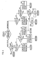
- Fig. 3 is a flow chart representing an operation related to control of LCD 29 by system controller 1.
- system controller 1 determines, in step S1, whether the digital still camera is set to the image pickup mode or the reproduction mode by mode switch 11, and when it is set to the image pickup mode, the control proceeds to step S2.
- step S2 system controller 1 determines whether lens cover switch 14 is on or not. When lens cover switch 14 is on, the flow proceeds to step S3 and if not, the flow returns to step S1.
- System controller 1 determines, in step S3, whether digital still camera is connected to personal computer 41 or not. When it is connected, power supply of LCD 29 is turned off in step S4, no matter whether the digital still camera is connected to television receiver 45 or not, and no matter whether LCD switch 12 is on or off. This is because LCD 29 is unnecessary when digital still camera is connected to personal computer 41, as digital still cameral is controlled by personal computer 41.
- step S5 system controller 1 determines in step S5, whether LCD switch 12 is on or not.
- power supply of LCD 29 is turned on in step S6 no matter whether the digital still camera is connected to television receiver 45 or not.
- step S7 power supply of LCD 2 is turned off in step S7 no matter whether the digital still camera is connected to television receiver 45 or not.
- LCD 29 may or may not be necessary. Therefore, use of LCD 29 is determined by the user of the digital still camera.
- step S8 determines in step S8 whether the digital still camera is connected to personal computer 41 or not. When it is connected, power supply of LCD 29 is turned off in step S9 no matter whether the digital still camera is connected to television receiver 45 or not, and no matter whether LCD switch 12 is on or not.
- step S10 determines in step S10 whether the digital still camera is connected to television receiver 45 or not. If it is not connected, power supply of LCD 29 is turned on in step S11, no matter whether the LCD switch 12 is on/off. In step S11, power supply of LCD 29 is turned on regardless of on/off of LCD switch 12, since LCD 29 is necessarily used when the digital still camera is connected neither to personal computer 41 nor television receiver 45 in the reproduction mode.
- step S10 When it is determined in step S10 that the digital still camera is connected to television receiver 45, system controller 1 determines in step S12 whether LCD switch 12 is on or not. When it is on, power supply of LCD 29 is turned on in step S13, and if LCD switch 12 is not on in step S12, power supply of LCD 29 is turned off in step S14.
Landscapes
- Engineering & Computer Science (AREA)
- Multimedia (AREA)
- Signal Processing (AREA)
- Studio Devices (AREA)
Claims (5)
- Digitalkamera mit einem Bildaufnahmemodus zum Aufnehmen und Aufzeichnen eines Bildes und einem Wiedergabemodus zum Wiedergeben des aufgezeichneten Bildes mit:einem Bildanzeigegerät (29), das geeignet ist, ein aufzuzeichnendes Bild oder ein wiedergegebenes Bild anzuzeigen,einem Schalter (12), der durch einen Benutzer der Digitalkamera betätigt wird, zum Anweisen der Lieferung und der Beendigung der Lieferung von Leistung an das Bildanzeigegerät (29),einem Digitalsignalausgabeanschluss (31), der geeignet ist, ein digitales Bildsignal an eine externe Verarbeitungseinheit (41) zu liefern,einem ersten Detektorsensor (2), der geeignet ist, eine Verbindung des Digitalsignalausgabeanschlusses (31) mit der Verarbeitungseinheit (41) zu erfassen,einem Analogsignalausgabeanschluss (32), der geeignet ist, ein analoges Bildsignal an einen externen Fernsehempfänger (35) zu liefern, um eine Bildanzeige auf dem Fernsehempfänger (45) zu ermöglichen,einem zweiten Detektorsensor (3), der geeignet ist, die Verbindung des analogen Signalausgabeanschlusses (32) mit dem Fernsehempfänger (45) zu erfassen, undeiner Steuerung (1), die abhängig von einem Befehl, der durch den Schalter (12) eingegeben wird, und von Erfassungsergebnissen durch den ersten Detektorsensor (2) und den zweiten Detektorsensor (3) arbeitet, die geeignet ist, die Spannungsversorgung an das Bildanzeigegerät (29) zu steuern,wobei die Steuerung (1) ausgebildet ist, die Spannungsversorgung an das Bildanzeigegerät (29) zu beenden, unabhängig davon, ob der Beginn der Spannungsversorgung durch den Schalter (12) angewiesen wird oder nicht oder ob durch den zweiten Detektorsensor (3) erfasst wird, dass der Analogsignalausgabeanschluss (32) mit dem Fernsehempfänger (45) verbunden ist oder nicht, wenn durch den ersten Detektorsensor (2) festgestellt wird, dass der Digitalsignalausgabeanschluss (31) mit der Verarbeitungseinheit (41) in dem Aufnahmemodus verbunden ist, undwobei die Steuerung (1) ausgebildet ist, die Spannungsversorgung an das Bildanzeigegerät (29) unabhängig davon zu beenden, ob durch den zweiten Detektorsensor (3) erfasst wird, dass der Analogsignalausgabeanschluss (32) mit dem Fernsehempfänger (45) verbunden ist oder nicht, falls das Beenden der Spannungsversorgung durch den Schalter (12) angewiesen wird, und ausgebildet ist, Leistung an das Bildanzeigegerät (29) zu liefern, unabhängig davon, ob durch den zweiten Detektorsensor (3) erfasst wird, dass der Analogsignalausgabeanschluss (32) mit dem Fernsehempfänger (45) verbunden ist oder nicht, falls der Beginn der Spannungsversorgung durch den Schalter (12) angewiesen wird, wenn durch den ersten Detektorsensor (2) erfasst wird, dass der Digitalsignalausgabeanschluss (31) nicht in dem Bildaufnahmemodus mit der Verarbeitungseinheit (41) verbunden ist.
- Digitalkamera nach Anspruch 1, wobei die Steuerung (1) ausgebildet ist, die Spannungsversorgung an das Bildanzeigegerät (29) zu beenden, unabhängig von einer Anweisung durch den Schalter (12) und ob durch den zweiten Detektorsensor (3) erfasst wird, dass der Analogsignalausgabeanschluss (32) mit dem Fernsehempfänger (45) verbunden ist oder nicht, wenn durch den ersten Detektorsensor (2) erfasst wird, dass der Digitalsignalausgabeanschluss (31) mit der Verarbeitungseinheit (41) in dem Wiedergabemodus verbunden ist,wobei die Steuerung (1) ausgebildet ist, die Spannungsversorgung an das Bildanzeigegerät (29) zu beenden, falls das Beenden der Spannungsversorgung durch den Schalter (12) angewiesen wird, und ausgebildet ist, Leistung an das Bildanzeigegerät (29) zu liefern, falls der Beginn der Spannungsversorgung durch den Schalter (12) angewiesen wird, wenn durch den ersten Detektorsensor (2) erfasst wird, dass der Digitalsignalausgabeanschluss (31) nicht mit der Verarbeitungseinheit (41) verbunden ist, und durch den zweiten Detektorsensor (3) festgestellt wird, dass der Analogsignalausgabeanschluss (32) mit dem Fernsehempfänger (45) in dem Wiedergabemodus verbunden ist,wobei die Steuerung (1) ausgebildet ist, Leistung an das Bildanzeigegerät (29) zu liefern, unabhängig davon, ob eine Anweisung durch den Schalter (12) vorliegt, wenn durch den ersten Detektorsensor (2) erfasst wird, dass der Digitalsignalausgabeanschluss (31) nicht mit der Verarbeitungseinheit (41) verbunden ist und durch den zweiten Detektorsensor (3) erfasst wird, dass der Analogsignalausgabeanschluss (32) nicht mit dem Fernsehempfänger (45) in dem Wiedergabemodus verbunden ist.
- Digitalkamera nach Anspruch 1 oder 2, wobei der Digitalsignalausgabeanschluss (31) vorgesehen ist zum Liefern eines Digitalbildsignales an die Verarbeitungseinheit (41) derart, dass das Bild auf einem Monitorgerät (42) angezeigt wird, der mit der Verarbeitungseinheit (41) verbunden ist.
- Digitalkamera mit einem Bildaufnahmemodus zum Aufnehmen und Aufzeichnen eines Bildes und einem Wiedergabemodus zum Wiedergeben des aufgezeichneten Bildes mit:einem Bildanzeigegerät (29), das geeignet ist, ein aufzunehmendes Bild oder ein wiedergegebenes Bild anzuzeigen,einem Schalter (12), der durch einen Benutzer der Digitalkamera betätigt wird, zum Anweisen des Beginns und der Beendigung der Leistungszufuhr an das Bildanzeigegerät (29),einem Digitalsignalausgabeanschluss (31), der geeignet ist, ein Digitalbildsignal an eine externe Verarbeitungseinheit (41) zu liefern,einem ersten Detektorsensor (2), der geeignet ist, eine Verbindung des Digitalsignalausgabeanschlusses (31) mit der Verarbeitungseinheit (41) zu erfassen,einem Analogsignalausgabeanschluss (32), der geeignet ist, ein Analogbildsignal an einen externen Fernsehempfänger (45) zu liefern, um eine Bildanzeige auf dem Fernsehempfänger (45) zu ermöglichen,einem zweiten Detektorsensor (3), der geeignet ist, eine Verbindung des Analogsignalausgabeanschlusses (32) mit dem Fernsehempfänger (45) zu erfassen, undeiner Steuerung (1), die abhängig von einem Befehl durch den Schalter (12) und von Detektorresultaten durch den ersten Detektorsensor (2) und den zweiten Detektorsensor (3) arbeitet, die geeignet ist, die Spannungsversorgung an das Bildanzeigegerät (29) zu steuern,wobei die Steuerung (1) ausgebildet ist, die Spannungsversorgung an das Bildanzeigegerät (29) unabhängig davon zu steuern, ob eine Anweisung durch den Schalter (12) vorliegt oder unabhängig von einem Verbindungszustand, der durch den zweiten Detektorsensor (3) für den Analogsignalausgabeanschluss (32) an den Fernsehempfänger (45) erfasst wird, wenn durch den ersten Detektorsensor (2) erfasst wird, dass der Digitalsignalausgabeanschluss (31) mit der Verarbeitungseinheit (41) in dem Wiedergabemodus verbunden ist,wobei die Steuerung ausgebildet ist, die Spannungsversorgung an das Bildanzeigegerät (29) zu beenden, falls die Beendigung der Spannungsversorgung durch den Schalter (12) angewiesen wird, und ausgebildet ist, Leistung an das Bildanzeigegerät (29) zu liefern, falls der Beginn der Spannungsversorgung durch den Schalter (12) angewiesen wird, wenn durch den ersten Detektorsensor (2) festgestellt wird, dass der Digitalsignalausgabeanschluss (31) nicht mit der Verarbeitungseinheit (41) verbunden ist, und durch den zweiten Detektorsensor (3) festgestellt wird, dass der Analogsignalausgabeanschluss (32) mit dem Fernsehempfänger (45) in dem Wiedergabemodus verbunden ist, undwobei die Steuerung (1) ausgebildet ist, Leistung an das Bildanzeigegerät (29) unabhängig von einem Befehl durch den Schalter (12) zu liefern, wenn durch den ersten Detektorsensor (2) festgestellt wird, dass der Digitalsignalausgabeanschluss (31) nicht mit der Verarbeitungseinheit (41) verbunden ist und durch den zweiten Detektorsensor (3) festgestellt wird, dass der Analogsignalausgabeanschluss (32) nicht mit dem Fernsehempfänger (45) in dem Wiedergabemodus verbunden ist.
- Digitalkamera nach Anspruch 4, wobei der Digitalsignalausgabeanschluss (31) vorgesehen ist zum Liefern eines Digitalbildsignals an die Verarbeitungseinheit (41) derart, dass das Bild auf einem Monitorgerät (42), das mit der Verarbeitungseinheit (41) verbunden ist, angezeigt wird.
Applications Claiming Priority (3)
| Application Number | Priority Date | Filing Date | Title |
|---|---|---|---|
| JP4366397 | 1997-02-27 | ||
| JP43663/97 | 1997-02-27 | ||
| JP04366397A JP3268995B2 (ja) | 1997-02-27 | 1997-02-27 | デジタルカメラ |
Publications (3)
| Publication Number | Publication Date |
|---|---|
| EP0862080A2 EP0862080A2 (de) | 1998-09-02 |
| EP0862080A3 EP0862080A3 (de) | 2004-04-28 |
| EP0862080B1 true EP0862080B1 (de) | 2007-12-05 |
Family
ID=12670102
Family Applications (1)
| Application Number | Title | Priority Date | Filing Date |
|---|---|---|---|
| EP98103382A Expired - Lifetime EP0862080B1 (de) | 1997-02-27 | 1998-02-26 | Bildaufnahme- und Bildwiedergabegerät |
Country Status (4)
| Country | Link |
|---|---|
| US (1) | US6844899B2 (de) |
| EP (1) | EP0862080B1 (de) |
| JP (1) | JP3268995B2 (de) |
| DE (1) | DE69838803T2 (de) |
Families Citing this family (16)
| Publication number | Priority date | Publication date | Assignee | Title |
|---|---|---|---|---|
| US20030063208A1 (en) * | 1996-06-12 | 2003-04-03 | Nikon Corporation | Image pick-up apparatus |
| TW448687B (en) * | 1998-03-09 | 2001-08-01 | Canon Kk | Image sensing apparatus having a protection cover |
| JP2000134527A (ja) * | 1998-10-26 | 2000-05-12 | Minolta Co Ltd | デジタルカメラ |
| JP2001036773A (ja) * | 1999-07-21 | 2001-02-09 | Canon Inc | 電子機器及びその制御方法並びにメモリ媒体 |
| JP2001285704A (ja) * | 2000-03-31 | 2001-10-12 | Canon Inc | 撮像装置、撮像方法及び記憶媒体 |
| JP4258098B2 (ja) * | 2000-05-31 | 2009-04-30 | 富士フイルム株式会社 | 電子カメラ |
| US6570621B2 (en) * | 2001-05-21 | 2003-05-27 | Hewlett-Packard Development Company, L.P. | Lens cap detection |
| US6867807B2 (en) * | 2001-09-04 | 2005-03-15 | Eastman Kodak Company | Camera having single-button timed display of most-recently viewed image and default display of last verification image and method |
| JP2003338980A (ja) * | 2002-05-20 | 2003-11-28 | Konica Minolta Holdings Inc | 撮影装置 |
| JP4064877B2 (ja) * | 2003-06-30 | 2008-03-19 | 株式会社東芝 | 複数表示画面を有するデジタルカメラ |
| JP2005277591A (ja) * | 2004-03-23 | 2005-10-06 | Toshiba Corp | 電子カメラ装置、及び撮像信号生成方法 |
| KR100586981B1 (ko) * | 2004-05-12 | 2006-06-08 | 삼성전자주식회사 | 컴퓨터시스템 및 그 제어방법 |
| JP2006318585A (ja) * | 2005-05-13 | 2006-11-24 | Sony Corp | 電子機器、データ処理方法及びプログラム |
| TW200822700A (en) * | 2006-11-03 | 2008-05-16 | Innolux Display Corp | Display system and display method thereof |
| JP5683790B2 (ja) * | 2009-03-03 | 2015-03-11 | 日立マクセル株式会社 | テレビジョン受信装置 |
| US20100283868A1 (en) * | 2010-03-27 | 2010-11-11 | Lloyd Douglas Clark | Apparatus and Method for Application of Selective Digital Photomontage to Motion Pictures |
Family Cites Families (20)
| Publication number | Priority date | Publication date | Assignee | Title |
|---|---|---|---|---|
| US5070406A (en) * | 1983-12-24 | 1991-12-03 | Canon Kabushiki Kaisha | Image sensing apparatus having a low-resolution monitor, means for reducing the amount of information in an image signal, and switching means for reducing power consumption in various operating modes |
| JPS6430969A (en) | 1987-07-27 | 1989-02-01 | Yamaha Motor Co Ltd | Sprocket |
| JPH01126659U (de) * | 1988-02-10 | 1989-08-30 | ||
| GB2225687B (en) * | 1988-10-04 | 1993-11-03 | Asahi Optical Co Ltd | Mode changing device for a still video camera |
| US5231501A (en) * | 1989-05-25 | 1993-07-27 | Asahi Kogaku Kogyo Kabushiki Kaisha | Still video apparatus |
| JPH03166880A (ja) | 1989-11-27 | 1991-07-18 | Seiko Epson Corp | 電子スチルカメラ |
| JPH0458680A (ja) * | 1990-06-28 | 1992-02-25 | Canon Inc | 磁気記録再生装置 |
| JPH05176294A (ja) * | 1991-12-25 | 1993-07-13 | Ricoh Co Ltd | デジタル電子スチルカメラ及び画像再生方法 |
| US5479206A (en) * | 1992-02-04 | 1995-12-26 | Fuji Photo Film Co., Ltd. | Imaging system, electronic camera, computer system for controlling said electronic camera, and methods of controlling same |
| JPH06153043A (ja) * | 1992-10-29 | 1994-05-31 | Sanyo Electric Co Ltd | カメラ一体型vtr |
| JPH06181527A (ja) * | 1992-12-14 | 1994-06-28 | Hitachi Ltd | Vtr一体型カメラ |
| JP3548191B2 (ja) * | 1993-03-22 | 2004-07-28 | キヤノン株式会社 | カメラ |
| JPH06303478A (ja) * | 1993-04-09 | 1994-10-28 | Sony Corp | 撮像装置 |
| JPH0746526A (ja) | 1993-07-29 | 1995-02-14 | Konica Corp | デジタル・スチル・カメラ |
| JP3400084B2 (ja) * | 1994-04-27 | 2003-04-28 | ソニー株式会社 | ビデオカメラ一体型ビデオテープレコーダ |
| JP3542653B2 (ja) * | 1995-02-14 | 2004-07-14 | 富士写真フイルム株式会社 | 電子スチルカメラにおける画像データ伝送システム |
| US5815201A (en) * | 1995-02-21 | 1998-09-29 | Ricoh Company, Ltd. | Method and system for reading and assembling audio and image information for transfer out of a digital camera |
| US5917545A (en) * | 1995-08-31 | 1999-06-29 | Nikon Corporation | Electronic still camera that can be directly inserted in an external device |
| US5633678A (en) * | 1995-12-20 | 1997-05-27 | Eastman Kodak Company | Electronic still camera for capturing and categorizing images |
| JPH09270944A (ja) | 1996-04-02 | 1997-10-14 | Canon Inc | 電子スチルカメラ |
-
1997
- 1997-02-27 JP JP04366397A patent/JP3268995B2/ja not_active Expired - Fee Related
-
1998
- 1998-02-25 US US09/030,360 patent/US6844899B2/en not_active Expired - Fee Related
- 1998-02-26 EP EP98103382A patent/EP0862080B1/de not_active Expired - Lifetime
- 1998-02-26 DE DE69838803T patent/DE69838803T2/de not_active Expired - Lifetime
Also Published As
| Publication number | Publication date |
|---|---|
| DE69838803D1 (de) | 2008-01-17 |
| US20010012071A1 (en) | 2001-08-09 |
| JPH10243324A (ja) | 1998-09-11 |
| EP0862080A2 (de) | 1998-09-02 |
| EP0862080A3 (de) | 2004-04-28 |
| DE69838803T2 (de) | 2008-11-20 |
| JP3268995B2 (ja) | 2002-03-25 |
| US6844899B2 (en) | 2005-01-18 |
Similar Documents
| Publication | Publication Date | Title |
|---|---|---|
| EP0862080B1 (de) | Bildaufnahme- und Bildwiedergabegerät | |
| US6327001B1 (en) | Image processing system and information processing apparatus | |
| US6774935B1 (en) | Digital camera | |
| US6630958B2 (en) | Method and apparatus for storing and displaying an image taken by a rotatable image pickup portion | |
| US6122411A (en) | Method and apparatus for storing high and low resolution images in an imaging device | |
| JPH09230495A (ja) | デジタルカメラ、外部記憶装置およびこれらのシステム | |
| US20020003579A1 (en) | Image sensing apparatus and control method thereof | |
| US7443425B2 (en) | Image pickup apparatus, control method therefor, control program for implementing the control method, and storage medium storing the control program | |
| US7496273B2 (en) | Data recording apparatus and data recording method | |
| US7518653B2 (en) | Digital camera having a plurality of operation modes of different power consumption | |
| US6856348B1 (en) | Camera capable of changing the number of image files stored in a current directory according to an image pickup mode | |
| US7015959B1 (en) | Image pickup apparatus for picking up and recording still or moving images and a method for controlling the same | |
| CN100531305C (zh) | 摄像装置中的显示转换控制 | |
| US20040032490A1 (en) | Image sensing apparatus, image sensing method, program, and storage medium | |
| US6674467B1 (en) | Digital still camera with image preview using a first and second memory and method for using the same | |
| EP0667622B1 (de) | Elektronische Standbildkamera | |
| JP4261815B2 (ja) | 撮像装置 | |
| JP2003274366A (ja) | 画像処理装置、画像処理方法、プログラム及び記録媒体 | |
| JPH11259506A (ja) | 画像処理装置、画像処理方法および記録媒体 | |
| US6968118B1 (en) | Image processing apparatus, its control method, and storage medium | |
| JP2003244486A (ja) | 撮像装置および画像再生装置 | |
| JP3696962B2 (ja) | ビデオカメラ | |
| JP2002094855A (ja) | 画像処理装置、撮像装置、画像処理装置の制御方法及び記憶媒体 | |
| JP3808191B2 (ja) | デジタルカメラ | |
| JP2001320612A (ja) | 画像処理装置 |
Legal Events
| Date | Code | Title | Description |
|---|---|---|---|
| PUAI | Public reference made under article 153(3) epc to a published international application that has entered the european phase |
Free format text: ORIGINAL CODE: 0009012 |
|
| AK | Designated contracting states |
Kind code of ref document: A2 Designated state(s): AT BE CH DE DK ES FI FR GB GR IE IT LI LU MC NL PT SE |
|
| AX | Request for extension of the european patent |
Free format text: AL;LT;LV;MK;RO;SI |
|
| PUAL | Search report despatched |
Free format text: ORIGINAL CODE: 0009013 |
|
| AK | Designated contracting states |
Kind code of ref document: A3 Designated state(s): AT BE CH DE DK ES FI FR GB GR IE IT LI LU MC NL PT SE |
|
| AX | Request for extension of the european patent |
Extension state: AL LT LV MK RO SI |
|
| RIC1 | Information provided on ipc code assigned before grant |
Ipc: 7H 04N 1/00 B Ipc: 7H 04N 1/21 B Ipc: 7G 03B 19/02 A |
|
| 17P | Request for examination filed |
Effective date: 20040505 |
|
| AKX | Designation fees paid |
Designated state(s): DE FR GB |
|
| 17Q | First examination report despatched |
Effective date: 20050503 |
|
| GRAP | Despatch of communication of intention to grant a patent |
Free format text: ORIGINAL CODE: EPIDOSNIGR1 |
|
| GRAS | Grant fee paid |
Free format text: ORIGINAL CODE: EPIDOSNIGR3 |
|
| GRAA | (expected) grant |
Free format text: ORIGINAL CODE: 0009210 |
|
| AK | Designated contracting states |
Kind code of ref document: B1 Designated state(s): DE FR GB |
|
| REG | Reference to a national code |
Ref country code: GB Ref legal event code: FG4D |
|
| REF | Corresponds to: |
Ref document number: 69838803 Country of ref document: DE Date of ref document: 20080117 Kind code of ref document: P |
|
| EN | Fr: translation not filed | ||
| PLBE | No opposition filed within time limit |
Free format text: ORIGINAL CODE: 0009261 |
|
| STAA | Information on the status of an ep patent application or granted ep patent |
Free format text: STATUS: NO OPPOSITION FILED WITHIN TIME LIMIT |
|
| 26N | No opposition filed |
Effective date: 20080908 |
|
| PG25 | Lapsed in a contracting state [announced via postgrant information from national office to epo] |
Ref country code: FR Free format text: LAPSE BECAUSE OF FAILURE TO SUBMIT A TRANSLATION OF THE DESCRIPTION OR TO PAY THE FEE WITHIN THE PRESCRIBED TIME-LIMIT Effective date: 20081003 |
|
| PGFP | Annual fee paid to national office [announced via postgrant information from national office to epo] |
Ref country code: GB Payment date: 20130220 Year of fee payment: 16 Ref country code: DE Payment date: 20130220 Year of fee payment: 16 |
|
| REG | Reference to a national code |
Ref country code: DE Ref legal event code: R119 Ref document number: 69838803 Country of ref document: DE |
|
| GBPC | Gb: european patent ceased through non-payment of renewal fee |
Effective date: 20140226 |
|
| REG | Reference to a national code |
Ref country code: DE Ref legal event code: R119 Ref document number: 69838803 Country of ref document: DE Effective date: 20140902 |
|
| PG25 | Lapsed in a contracting state [announced via postgrant information from national office to epo] |
Ref country code: GB Free format text: LAPSE BECAUSE OF NON-PAYMENT OF DUE FEES Effective date: 20140226 Ref country code: DE Free format text: LAPSE BECAUSE OF NON-PAYMENT OF DUE FEES Effective date: 20140902 |