EP0860901B1 - Housing for electric apparatus an electrical apparatus comprising the same - Google Patents
Housing for electric apparatus an electrical apparatus comprising the same Download PDFInfo
- Publication number
- EP0860901B1 EP0860901B1 EP98410007A EP98410007A EP0860901B1 EP 0860901 B1 EP0860901 B1 EP 0860901B1 EP 98410007 A EP98410007 A EP 98410007A EP 98410007 A EP98410007 A EP 98410007A EP 0860901 B1 EP0860901 B1 EP 0860901B1
- Authority
- EP
- European Patent Office
- Prior art keywords
- case
- walls
- electrical
- latching
- flanges
- Prior art date
- Legal status (The legal status is an assumption and is not a legal conclusion. Google has not performed a legal analysis and makes no representation as to the accuracy of the status listed.)
- Expired - Lifetime
Links
Images


Classifications
-
- H—ELECTRICITY
- H01—ELECTRIC ELEMENTS
- H01H—ELECTRIC SWITCHES; RELAYS; SELECTORS; EMERGENCY PROTECTIVE DEVICES
- H01H71/00—Details of the protective switches or relays covered by groups H01H73/00 - H01H83/00
- H01H71/08—Terminals; Connections
-
- H—ELECTRICITY
- H01—ELECTRIC ELEMENTS
- H01H—ELECTRIC SWITCHES; RELAYS; SELECTORS; EMERGENCY PROTECTIVE DEVICES
- H01H71/00—Details of the protective switches or relays covered by groups H01H73/00 - H01H83/00
- H01H71/02—Housings; Casings; Bases; Mountings
-
- H—ELECTRICITY
- H01—ELECTRIC ELEMENTS
- H01R—ELECTRICALLY-CONDUCTIVE CONNECTIONS; STRUCTURAL ASSOCIATIONS OF A PLURALITY OF MUTUALLY-INSULATED ELECTRICAL CONNECTING ELEMENTS; COUPLING DEVICES; CURRENT COLLECTORS
- H01R13/00—Details of coupling devices of the kinds covered by groups H01R12/70 or H01R24/00 - H01R33/00
- H01R13/46—Bases; Cases
- H01R13/502—Bases; Cases composed of different pieces
- H01R13/506—Bases; Cases composed of different pieces assembled by snap action of the parts
-
- H—ELECTRICITY
- H01—ELECTRIC ELEMENTS
- H01R—ELECTRICALLY-CONDUCTIVE CONNECTIONS; STRUCTURAL ASSOCIATIONS OF A PLURALITY OF MUTUALLY-INSULATED ELECTRICAL CONNECTING ELEMENTS; COUPLING DEVICES; CURRENT COLLECTORS
- H01R9/00—Structural associations of a plurality of mutually-insulated electrical connecting elements, e.g. terminal strips or terminal blocks; Terminals or binding posts mounted upon a base or in a case; Bases therefor
- H01R9/22—Bases, e.g. strip, block, panel
- H01R9/223—Insulating enclosures for terminals
Definitions
- the electrical terminal block includes dielectric separation means comprising a flange so as to increase an insulation distance between two terminals, electrical connection means, the dielectric separations being in contact with the walls of outline of the case.
- the side walls of the flanges include projections 18 comprising a second hooking device for fixing the said side walls at the first part 12 of the electrical terminal blocks.
- This second device for attachment comprises for example elastic tabs 19 cut from the mass of projections and openings 20 located in the first part of the electrical terminal blocks.
- an electrical circuit 25 is disposed between the two flanges 1 and 2.
- the terminal blocks preferably include insulating partitions 29 arranged between the terminals. These insulating partitions advantageously include a rim 30 of width greater than that of the partition so as to increase the insulation distance between the terminals.
- the flange 30 comes contact with the upstream or downstream contour walls so as to ensure the continuity of electrical insulation and a high insulation distance outside said walls of outline of the case.
Description
L'invention concerne un boítier pour appareillage électrique comportant :
- un premier flasque comprenant une première paroi latérale et des premières parois de contour disposées sensiblement perpendiculairement au bord de la première paroi latérale,
- un second flasque comprenant une seconde paroi latérale et des secondes parois de contour disposées sensiblement perpendiculairement au bord de la seconde paroi latérale,
- des moyens de maintien des premier et second flasques face à face, les premières et les secondes parois de contour étant en contact, et
- au moins un bloc de jonction électrique disposé sur une partie externe du boítier.
- a first flange comprising a first side wall and first contour walls arranged substantially perpendicular to the edge of the first side wall,
- a second flange comprising a second side wall and second contour walls arranged substantially perpendicular to the edge of the second side wall,
- means for holding the first and second flanges face to face, the first and second contour walls being in contact, and
- at least one electrical terminal block disposed on an external part of the housing.
Un tel boítier pour appareillage électrique est connu du document DE 29606759 U1 dans lequel les flasques du boítier sont maintenus l'un à l'autre seulement par des moyens d'accrochage intégrés dans les parois de contour desdits flasques.Such a box for electrical apparatus is known from document DE 29606759 U1 in which the flanges of the housing are held together only by means attachment integrated in the contour walls of said flanges.
Des boítiers pour appareillage électrique modulaire comportent de manière connue deux flasques ou deux demi-coquilles à assembler. Généralement, les deux flasques sont disposés l'un contre l'autre puis assemblés par des vis ou des rivets. Chaque flasque comprend généralement des colonnes de forme cylindrique et ouvertes sur les parois dudit flasque de manière à pouvoir introduire les rivets ou les vis.Boxes for modular electrical equipment comprise in known manner two flanges or two half-shells to assemble. Generally, the two flanges are arranged one against the other and then assembled by screws or rivets. Each flange includes generally columns of cylindrical shape and open on the walls of said flange of so you can insert the rivets or screws.
Lors de l'assemblage, des colonnes complémentaires de chaque flasque sont disposées dans le prolongement de leurs axes respectifs afin d'introduire les rivets. Après avoir été introduits dans chaque colonne, les rivets sont sertis à l'aide d'un outil spécial.During assembly, complementary columns of each flange are arranged in the extension of their respective axes in order to introduce the rivets. After being introduced in each column, the rivets are crimped using a special tool.
L'assemblage par vis est réalisé selon le même principe. Les vis sont introduites dans les colonnes puis vissées dans des écrous. Il est également possible de visser les vis directement dans la masse du boítier. Dans ce cas, les vis traversent librement une première colonne ayant un diamètre intérieur plus grand que le diamètre des vis. Puis, les vis sont vissées dans une seconde colonne complémentaire ayant un diamètre intérieur plus petit que le diamètre des vis.The assembly by screws is carried out according to the same principle. The screws are inserted in the columns then screwed into nuts. It is also possible to screw the screws directly in the mass of the case. In this case, the screws pass freely through a first column having an inside diameter larger than the diameter of the screws. Then the screws are screwed into a second complementary column having an inner diameter smaller than the diameter of the screw.
L'assemblage par rivets ou par vis nécessite des outils spéciaux. Ceci conduit à un temps de montage important et à un coût de fabrication des appareils très élevé. De plus, ces modes de fixation ne permettent pas d'avoir des boítiers indémontables. En effet, il est facile de démonter un boítier fixé par des vis ou d'enlever un rivet et le remplacer par un autre.Assembly using rivets or screws requires special tools. This leads to a time of significant assembly and very high cost of manufacturing the devices. In addition, these modes of fixing do not allow to have non-removable cases. Indeed, it is easy to dismantle a case fixed by screws or remove a rivet and replace it with another.
L'invention a pour but un boítier pour appareillage électrique pouvant être assemblé rapidement sans outils spéciaux ainsi qu'un appareil électrique comportant un tel boítier. The object of the invention is to provide a housing for electrical equipment which can be assembled. quickly without special tools and an electrical device comprising such a housing.
Selon l'invention les moyens de maintien du boítier comportent au moins un bloc de jonction électrique disposé sur une partie externe du boítier pour relier une face extérieure de la première paroi latérale à une face extérieure de la seconde paroi latérale, ledit bloc de jonction électrique comprenant une première partie disposée à l'extérieur des parois de contour et deux parois de maintien perpendiculaires à ladite première partie et disposées sur les faces extérieures des premières et des secondes parois latérales.According to the invention the housing holding means comprise at least one terminal block electric disposed on an external part of the case to connect an external face of the first side wall to an outer face of the second side wall, said terminal block electric comprising a first part arranged outside the contour walls and two retaining walls perpendicular to said first part and arranged on the faces exterior of the first and second side walls.
Selon un mode de réalisation préférentiel, les parois de maintien du bloc de jonction électrique comportent des premiers moyens d'accrochage coopérant avec des formes appropriées des parois latérales pour fixer ledit bloc de jonction électrique sur le boítier.According to a preferred embodiment, the retaining walls of the electrical terminal block comprise first attachment means cooperating with appropriate forms of the side walls for fixing said electrical terminal block on the housing.
De préférence, les premiers moyens d'accrochage des parois de maintien du bloc de jonction électrique sont des languettes comportant des ergots d'accrochage destinés à coopérer avec des encoches situées dans les parois latérales du boítier.Preferably, the first means for hooking the retaining walls of the terminal block electrical are tongues comprising latching lugs intended to cooperate with notches located in the side walls of the case.
Avantageusement, les première et seconde parois latérales comportent des avancées comprenant des seconds moyens d'accrochage pour fixer lesdites parois latérales sur la première partie du bloc de jonction électrique.Advantageously, the first and second side walls include projections comprising second attachment means for fixing said side walls on the first part of the electrical terminal block.
Dans un mode de réalisation particulier, les flasques comportent des troisièmes moyens d'accrochage disposés sur les faces internes des parois pour maintenir les flasques dans leurs positions respectives.In a particular embodiment, the flanges include third means hooks arranged on the inner faces of the walls to keep the flanges in their respective positions.
De préférence, les troisièmes moyens d'accrochage comportent des languettes souples munies d'ergots d'accrochage à leur extrémité et disposées dans le prolongement de parois de contour, et des encoches situées dans des parois de contour à l'opposé des languettes pour recevoir les ergots d'accrochage.Preferably, the third attachment means comprise flexible tabs provided hooking lugs at their end and arranged in the extension of contour walls, and notches located in contour walls opposite the tabs to receive the hooking lugs.
Avantageusement, les troisièmes moyens d'accrochage comportent au moins trois points de fixation sur les parois de contour, un premier point de fixation étant situé vers le fond du boítier, un second point de fixation étant situé vers un côté amont du boítier, et un troisième point de fixation étant situé vers un côté aval du boítier. Advantageously, the third attachment means comprise at least three points of attachment to the contour walls, a first attachment point being located towards the bottom of the housing, a second attachment point being located towards an upstream side of the housing, and a third attachment point being located towards a downstream side of the housing.
Pour rendre le boítier indémontable, les troisièmes moyens d'accrochage sont disposés de manière peu accessible par l'extérieur des parois pour empêcher l'ouverture du boítier sans déformation des flasques.To make the housing non-removable, the third attachment means are arranged not easily accessible from the outside of the walls to prevent opening of the housing without deformation of the flanges.
Le boítier comporte un capot constituant la face avant dudit boítier et fixé par des moyens de fixation par accrochage sur des parois des flasques, lesdits moyens de fixation par accrochage n'étant pas manoeuvrables par l'extérieur du boítier, et les parois de contour ayant une ouverture située vers la face avant du boítier.The housing comprises a cover constituting the front face of said housing and fixed by means of fixing by hooking on the walls of the flanges, said means of fixing by hooking not being maneuverable from the outside of the case, and the contour walls having a opening located towards the front face of the case.
Pour le raccordement du boítier, le bloc de jonction électrique comporte des alvéoles destinées à recevoir des moyens de connexion électrique coopérant avec des conducteurs disposés entre l'intérieur et l'extérieur du boítier.For the connection of the box, the electrical terminal block has cells intended to receive electrical connection means cooperating with conductors arranged between inside and outside of the case.
De préférence, le bloc de jonction électrique comporte des moyens de séparation diélectrique comportant un rebord de manière à augmenter une distance d'isolement entre deux bornes, des moyens de connexion électrique, les séparations diélectriques étant en contact avec les parois de contour du boítier.Preferably, the electrical terminal block includes dielectric separation means comprising a flange so as to increase an insulation distance between two terminals, electrical connection means, the dielectric separations being in contact with the walls of outline of the case.
Un appareil électrique selon un mode de réalisation de l'invention comporte un boítier selon des modes de réalisation décrits ci-dessus, un circuit électrique disposé à l'intérieur dudit boítier, et des conducteurs électriques connectés audit circuit et traversant les parois de contour pour coopérer avec des bornes des moyens de connexion électriques d'un bloc de jonction.An electrical appliance according to an embodiment of the invention comprises a housing according to of the embodiments described above, an electrical circuit arranged inside said housing, and electrical conductors connected to said circuit and passing through the walls of contour to cooperate with terminals of the electrical connection means of a block of junction.
Dans un mode de réalisation particulier d'un appareil, les conducteurs électriques sont en cuivre plat préformé connecté à un circuit imprimé disposé dans le boítier, la forme des conducteurs ayant une première partie connectée perpendiculairement au plan du circuit imprimé, une seconde partie pliée par rapport à la première partie et une troisième partie sortant de la paroi de contour. In a particular embodiment of an apparatus, the electrical conductors are in preformed flat copper connected to a printed circuit placed in the housing, the shape of conductors having a first part connected perpendicular to the plane of the circuit printed, a second part folded with respect to the first part and a third part coming out of the contour wall.
De préférence, la première partie des conducteurs comporte deux extrémités pouvant être connectées au circuit, la seconde partie du connecteur étant plus proche d'une première extrémité pour rendre le conducteur de liaison réversible.Preferably, the first part of the conductors has two ends which can be connected to the circuit, the second part of the connector being closer to a first end to make the connecting conductor reversible.
D'autres avantages et caractéristiques ressortiront plus clairement de la description qui va suivre, de modes particuliers de réalisation de l'invention, donnés à titre d'exemples non limitatifs, et représentés aux dessins annexés sur lesquels :
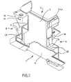
- La figure 1 représente un premier mode de réalisation d'un flasque pour un boítier selon l'invention,
- La figure 2 représente un mode de réalisation d'un second flasque complémentaire du premier flasque de la figure 1,
- Les figures 3 et 4 représentent des modes de réalisation de blocs de jonction électrique pour un boítier selon l'invention,
- La figure 5 représente un capot de face avant pour un boítier selon les figures 1 et 2,
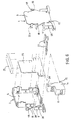
- La figure 6 représente l'assemblage d'un appareil électrique comportant un boítier selon les figures 1 à 5,
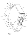
- La figure 7 représente un boítier monté comportant des éléments selon les figures 1 à 5,
- Les figures 8 et 9 représentent des modes de réalisation de conducteurs de liaison pour des appareils comportant un boítier selon l'invention,
- La figure 10 montre la disposition d'un conducteur de liaison entre un circuit imprimé et une borne.
- FIG. 1 represents a first embodiment of a flange for a housing according to the invention,
- FIG. 2 represents an embodiment of a second flange complementary to the first flange of FIG. 1,
- FIGS. 3 and 4 represent embodiments of electrical terminal blocks for a box according to the invention,
- FIG. 5 represents a front cover for a housing according to FIGS. 1 and 2,
- FIG. 6 represents the assembly of an electrical appliance comprising a housing according to FIGS. 1 to 5,
- FIG. 7 represents a mounted housing comprising elements according to FIGS. 1 to 5,
- FIGS. 8 and 9 show embodiments of connecting conductors for devices comprising a box according to the invention,
- Figure 10 shows the arrangement of a connecting conductor between a printed circuit and a terminal.
Un boítier modulaire pour appareillage électrique selon un mode de réalisation comporte un
premier flasque 1 et un second flasque 2 représentés respectivement sur les figures 1 et 2. Le
premier flasque 1 comporte une première paroi 3 latérale et des premières parois de contour 4.
Le second flasque 2 comporte également une seconde paroi 5 latérale et des secondes parois
de contour 6. Pour le montage du boítier, les flasques sont disposés face à face et les
premières et secondes parois de contour sont positionnées en contact de manière à fermer le
contour dudit boítier. Ainsi formé, le boítier comporte un fond 7 destiné à être fixé sur un
support, un premier côté amont 8 et un second côté aval 9 perpendiculaires au fond et aux
parois latérales. Le support est, de préférence, un rail symétrique.A modular box for electrical equipment according to one embodiment comprises a
Selon un mode de réalisation de l'invention, les flasques 1 et 2 sont maintenues par des blocs
de jonction électrique 10 et 11 représentés sur les figures 3 et 4. Chaque bloc de jonction
électrique comporte une première partie 12 destinée à être en contact avec un côté amont ou
aval des parois de contour, et deux parois de maintien 13 et 14 perpendiculaires à ladite
première partie. Chaque paroi de maintien des blocs de jonction électrique est en contact avec
une face extérieure de chaque paroi latérale pour maintenir les flasques face à face dans leur
positon respective.According to one embodiment of the invention, the
Les parois de maintien comportent un premier dispositif d'accrochage pour fixer les blocs de
jonction électrique sur les parois des flasques. Ce dispositif comporte de préférence des
languettes 15 prolongeant les parois de maintien et comportant des ergots 16 d'accrochage
destinés à coopérer avec des encoches 17 situées dans les parois latérales du boítier.The retaining walls comprise a first attachment device for fixing the blocks of
electrical junction on the walls of the flanges. This device preferably includes
Pour assurer une fixation plus efficace du bloc de jonction, les parois latérales des flasques
comportent des avancées 18 comprenant un second dispositif d'accrochage pour fixer lesdites
parois latérales à la première partie 12 des blocs de jonction électrique. Ce second dispositif
d'accrochage comporte par exemple des languettes 19 élastiques découpées dans la masse des
avancées et des ouvertures 20 situées dans la première partie des blocs de jonction électrique.To ensure more efficient fixing of the terminal block, the side walls of the flanges
include
Lors de la mise en place des blocs de jonction électrique, pour maintenir les flasques, les
avancées 18 sont glissées sur la première partie 12 du bloc et les parois de maintien 14 sont
glissées sur les faces extérieures des parois latérales 3 et 5. Puis, en bout de course, lorsque le
bloc est en place, les languettes 15 s'accrochent sur les encoches 17 et les languettes 19 entrent
dans les ouvertures 20 pour bloquer le bloc de jonction électrique sur les flasques.When installing the electrical terminal blocks, to maintain the flanges, the
Lorsque les deux blocs de jonction électrique sont mis en place respectivement sur les côtés
amont et aval, les deux flasques sont solidarisés. Il est alors possible de mettre en place un
capot 21 sur la partie avant du boítier, à l'opposé du fond. Ce capot 21 est de préférence fixé
par un dispositif à accrochage. Ledit dispositif comporte par exemple des ergots d'accrochage
sur le bord du capot et des encoches au bord des parois de contour des flasques.When the two electrical terminal blocks are placed on the sides respectively
upstream and downstream, the two flanges are secured. It is then possible to set up a
Le montage d'un tel boítier est très facile et ne nécessite aucun outil particulier. En effet, le montage consiste à maintenir les flasques l'un contre l'autre, puis à mettre en place les blocs de jonction côté amont et côté aval jusqu'à l'accrochage des languettes, et à fixer le capot par simple pression. The assembly of such a housing is very easy and does not require any particular tool. Indeed, the mounting consists of holding the flanges against each other, then putting the blocks in place junction upstream side and downstream side until the tabs are hooked, and fix the cover by one touch.
Les flasques peuvent aussi être maintenus dans leurs positions respectives par un troisième dispositif de fixation à accrochage.The flanges can also be held in their respective positions by a third hooking fastening device.
Dans le mode de réalisation particulier des figures 1 et 2, ces dispositifs comportent
notamment des languettes 22a à 22d souples disposées sur des faces internes des parois
latérales dans le prolongement des parois de contour. Lesdites languettes comportent à leur
extrémité des ergots d'accrochage respectivement 23a et 23d. A l'opposé des languettes, les
parois de contour comportent des encoches 24a et 24d, ou des épaulements pour recevoir les
ergots d'accrochage et verrouiller la fermeture du boítier.In the particular embodiment of Figures 1 and 2, these devices include
in particular flexible tabs 22a to 22d arranged on internal faces of the walls
lateral in the extension of the contour walls. Said tabs have at their
end of the hooking
De préférence, le boítier comporte au moins trois points de fixation, un premier point
correspondant à une première languette 22a disposée sur le côté aval et coopérant avec une
première encoche 24a, un second point de fixation correspondant à une seconde languette
22b disposée sur le côté amont et coopérant avec une seconde encoche 24b, et un troisième
point de fixation correspondant à une troisième languette 22c ou 22d disposée sur le fond du
boítier et coopérant avec une troisième encoche respectivement 24c ou 24d.Preferably, the housing has at least three fixing points, a first point
corresponding to a first tab 22a disposed on the downstream side and cooperating with a
Pour garantir le fonctionnement de certains appareils électriques, il est nécessaire de rendre les boítiers indémontables ou difficilement démontables sans détérioration desdits boítiers. Dans des boítiers selon ce mode particulier de réalisation de l'invention, les languettes sont disposées de manière à ne plus être manoeuvrées pour séparer les flasques, toute tentative d'ouverture risquant de déformer le boítier.To guarantee the functioning of certain electrical devices, it is necessary to return the housings which cannot be dismantled or which are difficult to dismantle without damaging said housings. In housings according to this particular embodiment of the invention, the tongues are arranged so that they are no longer maneuvered to separate the flanges, any attempt opening may distort the case.
La figure 6 montre une vue éclatée d'un boítier selon le mode particulier de réalisation de l'invention et la figure 7 montre une vue d'un même boítier assemblé.Figure 6 shows an exploded view of a housing according to the particular embodiment of the invention and Figure 7 shows a view of the same assembled housing.
Dans un appareil électrique selon un mode de réalisation de l'invention, comportant un boítier
comme décrit ci-dessus, un circuit électrique 25 est disposé entre les deux flasques 1 et 2.In an electrical appliance according to an embodiment of the invention, comprising a housing
as described above, an
Selon un mode de réalisation préférentiel, les blocs de jonction électrique comportent des
alvéoles destinées à recevoir des bornes 26 de raccordement électrique. Lesdites bornes sont
prévues pour être associées à des conducteurs 27 de liaison disposés entre l'intérieur et
l'extérieur du boítier. De préférence, les bornes sont des bornes à cage comportant un étrier et
une vis de serrage pour maintenir un conducteur de liaison et un conducteur de ligne. Pour le
passage des conducteurs de liaison entre l'intérieur et l'extérieur du boítier, les parois de
contour comportent des ouvertures 28. According to a preferred embodiment, the electrical terminal blocks include
cells intended to receive
Les blocs de jonction comportent de préférence des cloisons isolantes 29 disposées entre les
bornes. Ces cloisons isolantes comportent avantageusement un rebord 30 de largeur
supérieure à celle de la cloison de manière à augmenter la distance d'isolement entre les
bornes. Lorsque le bloc de jonction est mis en place sur le boítier, le rebord 30 vient en
contact avec les parois de contour en amont ou en aval de manière à assurer la continuité de
l'isolement électrique et une distance d'isolement élevée à l'extérieur desdites parois de
contour du boítier.The terminal blocks preferably include insulating
Les conducteurs de liaison 27 peuvent être connectés à l'intérieur du boítier, à des circuits
imprimés 25 comportant des circuits électriques et éventuellement des composants
électroniques. Le plan des circuits imprimés étant généralement parallèle aux parois latérales,
lesdits conducteurs de liaison doivent avoir des formes particulières pour pouvoir relier les
bornes de sortie et lesdits circuits.The connecting
Dans des modes de réalisation préférentiels, les conducteurs électriques sont réalisés en cuivre
plat préformé et connectés au circuit imprimé par soudure ou sertissage d'une première
extrémité. Lesdits conducteurs représentés sur les figures 8 et 9 ont de préférence une
première partie 31 disposée perpendiculairement au plan du circuit imprimé, une seconde
partie 32 pliée par rapport à la première partie et une troisième partie 33 sortant des parois de
contour.In preferred embodiments, the electrical conductors are made of copper
preformed plate and connected to the printed circuit by soldering or crimping a first
end. Said conductors shown in Figures 8 and 9 preferably have a
La première partie comporte des découpes 34 de manière à pouvoir être soudée sur un circuit
imprimé par un ou plusieurs points de soudure 35. De préférence, ladite première partie
comporte deux extrémités opposées de manière à rendre les conducteurs de liaison réversibles,
la seconde partie étant plus proche d'une première extrémité que d'une seconde extrémité. Ce
type de conducteurs de liaison préférentiel permet de connecter deux conducteurs de liaison
dans le même plan de sortie et d'utiliser deux bornes côte à côte, lesdits conducteurs étant
disposés tête bêche comme sur les figures 8 et 9. Chaque extrémité de la première partie
comporte des découpes 34 pour pouvoir être soudée sur le circuit imprimé.The first part has
La figure 10 montre des conducteurs de liaison 27 connectés au circuit 25 et associés à des
bornes 26.FIG. 10
Les éléments du boítier décrits ci-dessus sont réalisés de préférence en matière plastique moulée. The elements of the housing described above are preferably made of plastic molded.
Les formes des flasques et des blocs de jonction électrique peuvent être différentes tout en exerçant les mêmes fonctions. Notamment, les formes des moyens d'accrochage peuvent être différentes de celles des languettes souples munies d'ergots.The shapes of the flanges and electrical terminal blocks can be different while performing the same functions. In particular, the shapes of the attachment means can be different from flexible tabs with lugs.
Le capot représenté sur les figures 5 et 7 est fermé, mais dans d'autres modes de réalisation, un capot peut avoir des ouvertures ou comporter des moyens de réglage, de manoeuvre ou de visualisation.The cover shown in FIGS. 5 and 7 is closed, but in other embodiments, a hood may have openings or include means for adjusting, operating or visualization.
La largeur des boítiers peut être variable, pour des boítiers modulaires elle est généralement égale à des multiples de 9mm, par exemple 18mm, 27mm, 36mm, ou 54mm. Dans ce cas, les blocs de jonction peuvent avoir un nombre important de bornes disposées côté à côte.The width of the boxes can be variable, for modular boxes it is generally equal to multiples of 9mm, for example 18mm, 27mm, 36mm, or 54mm. In this case, the Terminal blocks can have a large number of terminals arranged side by side.
Claims (14)
- A case for electrical apparatus comprising :a case characterized in that at least one of said means for securing the flanges is formed by one of said electrical junction blocks (10, 11), joining an external face of the first side wall (3) to an external face of the second side wall (5), said electrical junction block comprising a first part (12) arranged outside the circumferential walls and two securing walls (13, 14) perpendicular to said first part and arranged on the external faces of the first and second side walls.a first flange (1) comprising a first side wall (3) and first circumferential walls (4) arranged appreciably perpendicularly to the edge of the first side wall,a second flange (2) comprising a second side wall (5) and second circumferential walls (6) arranged appreciably perpendicularly to the edge of the second side wall, andmeans for securing the first and second flanges face to face, the first and second circumferential walls being in contact, andat least one electrical junction block arranged on an external part of the case,
- The case according to claim 1 characterized in that the securing walls of the electrical junction block comprise first latching means (15, 16) operating in conjunction with suitable forms (17) of the side walls to fix said electrical junction block onto the case.
- The case according to claim 2 characterized in that the first latching means of the securing walls of the electrical junction block are tabs (15) comprising latching splines (16) designed to operate electrical junction with notches (17) situated in the side walls of the case.
- The case according to claim 2 or 3 characterized in that the first and second side walls comprise projections (18) comprising second latching means (19) to fix said side walls onto the first part of the electrical junction block.
- The case according to any one of the claims 1 to 4 characterized in that the flanges comprise third latching means (22a-22d, 23a-23d, 24a-24d) arranged on the internal faces of the circumferential walls to hold the flanges in their respective positions.
- The case according to claim 5 characterized in that the third latching means comprise flexible tabs (22a-22d) provided with latching splines (23a-23d) at their ends and arranged in the extension of circumferential walls, and notches (24a-24d) situated in circumferential walls opposite the tabs to receive the latching splines.
- The case according to one of the claims 5 or 6 characterized in that the third latching means comprise at least three fixing points for fixing to the circumferential walls, a first fixing point (22c, 22d, 23c, 23d, 24c, 24d) being situated towards the back plate of the case, a second fixing point (22b, 23b, 24b) being situated towards an up-line side of the case, and a third fixing point (22a, 23a, 24a) being situated towards a down-line side of the case.
- The case according to any one of the claims 5 to 7 characterized in that the third latching means are arranged in a manner hardly accessible from the outside of the walls to prevent the case from being opened without the flanges being deformed.
- The case according to any one of the claims 1 to 8 characterized in that it comprises a cover (21) forming the front face of said case and fixed by means for fixing by latching onto walls of the flanges, said means for fixing by latching not being able to be touched from the outside of the case, and the circumferential walls having an opening situated towards the front face of the case.
- The case according to any one of the claims 1 to 9 characterized in that the electrical junction block comprises recesses designed to receive means for electrical connection (26) operating in conjunction with conductors (27) arranged between the inside and the outside of the case.
- The case according to claim 10 characterized in that the electrical junction block comprises means for dielectric separation (29) comprising an edge (30) so as to increase an isolation distance between two terminals (26) of the means for electrical connection, the dielectric separations being in contact with the circumferential walls of the case.
- An electrical apparatus comprising a case according to any one of the claims 1 to 11, an electrical circuit (25) arranged inside said case, and electrical conductors (27) connected to said circuit and passing through the circumferential walls to operate in conjunction with terminals of the means for electrical connection of said electrical junction blocks.
- The electrical apparatus according to claim 12 characterized in that the electrical conductors (27) are made of pre-formed flat copper connected to a printed circuit (25) arranged in the case, the form of the conductors having a first part (31) connected perpendicularly to the plane of the printed circuit, a second part (32) folded with respect to the first part and a third part (33) extending outside the circumferential wall.
- The electrical apparatus according to claim 13 characterized in that the first part of the conductors comprises two ends able to be connected to the circuit, the second part of the connector being closer to a first end to make the connecting conductor reversible.
Applications Claiming Priority (2)
| Application Number | Priority Date | Filing Date | Title |
|---|---|---|---|
| FR9701970 | 1997-02-14 | ||
| FR9701970A FR2759846B1 (en) | 1997-02-14 | 1997-02-14 | HOUSING FOR ELECTRICAL APPARATUS AND ELECTRICAL APPARATUS COMPRISING SUCH A HOUSING |
Publications (2)
| Publication Number | Publication Date |
|---|---|
| EP0860901A1 EP0860901A1 (en) | 1998-08-26 |
| EP0860901B1 true EP0860901B1 (en) | 2000-08-02 |
Family
ID=9503926
Family Applications (1)
| Application Number | Title | Priority Date | Filing Date |
|---|---|---|---|
| EP98410007A Expired - Lifetime EP0860901B1 (en) | 1997-02-14 | 1998-02-06 | Housing for electric apparatus an electrical apparatus comprising the same |
Country Status (10)
| Country | Link |
|---|---|
| EP (1) | EP0860901B1 (en) |
| CN (1) | CN1068698C (en) |
| AR (1) | AR011675A1 (en) |
| AT (1) | ATE195204T1 (en) |
| BR (1) | BR9800617B1 (en) |
| DE (1) | DE69800235T2 (en) |
| EA (1) | EA000360B1 (en) |
| ES (1) | ES2150307T3 (en) |
| FR (1) | FR2759846B1 (en) |
| ID (1) | ID19899A (en) |
Families Citing this family (4)
| Publication number | Priority date | Publication date | Assignee | Title |
|---|---|---|---|---|
| FR2904142B1 (en) * | 2006-07-19 | 2008-09-19 | Legrand France | ELECTRICAL EQUIPMENT WITH EASY WIRING. |
| DE102007032841A1 (en) | 2007-07-12 | 2009-01-15 | Abb Ag | Installation switching device with insulating housing |
| DE102008008374A1 (en) * | 2008-02-09 | 2009-08-13 | Abb Ag | Service switching device |
| DE102010005345B4 (en) | 2010-01-21 | 2022-04-21 | Abb Schweiz Ag | Electrical switching device in modular design |
Citations (1)
| Publication number | Priority date | Publication date | Assignee | Title |
|---|---|---|---|---|
| EP0849757A2 (en) * | 1996-12-20 | 1998-06-24 | ABBPATENT GmbH | Housing for an electrical installation device, in particular for a fault-current protective switch or a circuit breaker or the like |
Family Cites Families (6)
| Publication number | Priority date | Publication date | Assignee | Title |
|---|---|---|---|---|
| DE8135923U1 (en) * | 1981-12-10 | 1982-06-16 | Murr-Elektronik Gmbh, 7155 Oppenweiler | "Housing for electrical devices that can be assembled from several housing parts" |
| FR2635909B1 (en) * | 1988-08-30 | 1990-11-30 | Hager Electro | ELECTRICAL CONTROL AND / OR PROTECTIVE APPARATUSES, COMPONENTS MADE OF SUCH APPARATUSES AND ASSEMBLIES MADE OF SUCH ELEMENTS |
| FR2656464B1 (en) * | 1989-12-22 | 1992-03-27 | Merlin Gerin | INSULATING HOUSING FOR A PASSIVE OR SECTIONAL NEUTRAL DIFFERENTIAL CIRCUIT BREAKER. |
| FR2707429B1 (en) * | 1993-07-07 | 1995-09-01 | Merlin Gerin | Connection accessory. |
| DE29606759U1 (en) * | 1996-04-13 | 1996-06-27 | Kloeckner Moeller Gmbh | Multi-part housing in modular design to accommodate a circuit board |
| DE29606760U1 (en) * | 1996-04-13 | 1996-07-11 | Kloeckner Moeller Gmbh | Connector plug for fitting a circuit board that can be inserted into a housing |
-
1997
- 1997-02-14 FR FR9701970A patent/FR2759846B1/en not_active Expired - Fee Related
-
1998
- 1998-02-06 DE DE69800235T patent/DE69800235T2/en not_active Expired - Lifetime
- 1998-02-06 EP EP98410007A patent/EP0860901B1/en not_active Expired - Lifetime
- 1998-02-06 ES ES98410007T patent/ES2150307T3/en not_active Expired - Lifetime
- 1998-02-06 AT AT98410007T patent/ATE195204T1/en not_active IP Right Cessation
- 1998-02-12 ID IDP980187A patent/ID19899A/en unknown
- 1998-02-13 EA EA199800124A patent/EA000360B1/en not_active IP Right Cessation
- 1998-02-13 AR ARP980100671A patent/AR011675A1/en unknown
- 1998-02-14 CN CN98105969A patent/CN1068698C/en not_active Expired - Fee Related
- 1998-02-16 BR BRPI9800617-7A patent/BR9800617B1/en not_active IP Right Cessation
Patent Citations (1)
| Publication number | Priority date | Publication date | Assignee | Title |
|---|---|---|---|---|
| EP0849757A2 (en) * | 1996-12-20 | 1998-06-24 | ABBPATENT GmbH | Housing for an electrical installation device, in particular for a fault-current protective switch or a circuit breaker or the like |
Also Published As
| Publication number | Publication date |
|---|---|
| EA199800124A1 (en) | 1998-08-27 |
| FR2759846A1 (en) | 1998-08-21 |
| EP0860901A1 (en) | 1998-08-26 |
| CN1068698C (en) | 2001-07-18 |
| CN1192032A (en) | 1998-09-02 |
| AR011675A1 (en) | 2000-08-30 |
| ID19899A (en) | 1998-08-20 |
| ES2150307T3 (en) | 2000-11-16 |
| DE69800235T2 (en) | 2004-06-17 |
| FR2759846B1 (en) | 2003-12-26 |
| EA000360B1 (en) | 1999-06-24 |
| BR9800617A (en) | 1999-09-14 |
| DE69800235D1 (en) | 2000-09-07 |
| BR9800617B1 (en) | 2009-05-05 |
| ATE195204T1 (en) | 2000-08-15 |
Similar Documents
| Publication | Publication Date | Title |
|---|---|---|
| EP0619625B1 (en) | Elctrical connector with a plurality of connection modules ordered in lines and columnes | |
| FR2780206A1 (en) | ASSEMBLY FORMING AN ENERGY DISTRIBUTION BLOCK, AND AN ENERGY TRANSMISSION BAR | |
| EP0619626B1 (en) | Electrical connector with a number of connection modules | |
| FR2684242A1 (en) | ELECTRICAL CONNECTOR ASSEMBLY COMPRISING A TERMINAL LOCKING ELEMENT. | |
| WO2016128398A1 (en) | Electric heating device | |
| WO2016128395A1 (en) | Housing for an electric heating device | |
| EP0860901B1 (en) | Housing for electric apparatus an electrical apparatus comprising the same | |
| EP2849295B1 (en) | Electric distribution assembly comprising a multipole electric power distribution comb. | |
| WO2016128399A1 (en) | Electric heating device | |
| FR2621424A1 (en) | MECHANICAL ASSEMBLY DEVICE WITH AUTOCENTRING OF ELECTRICAL EQUIPMENT MODULES | |
| FR2637131A1 (en) | Assembly to be used with electrical conductors | |
| FR2797353A1 (en) | Connector for electric conductors e.g. for motor vehicles, has at least one electrically conductive bridge with as many end sections as electric conductors to be connected | |
| EP0259199B1 (en) | Electrical connector for a loudspeakerdriver | |
| EP1006549B1 (en) | Electromechanical switching apparatus | |
| EP0635902A1 (en) | Terminal and electrical connector module | |
| EP1107363B1 (en) | Monopolar modular distribution frame | |
| FR2809872A1 (en) | ELECTRICAL CONNECTION DEVICE FOR MALE ELECTRIC CONTACT MEMBER AND HOUSING ELEMENT FOR RECEIVING SUCH A DEVICE | |
| EP0416965A1 (en) | Device for the connection of a derived conductor to an insulated main conductor | |
| EP0552996B1 (en) | Female electrical contact element | |
| EP1676349A1 (en) | Electrical connection bar and adapted connection device | |
| FR2811812A1 (en) | CONNECTION CONNECTOR AND ELECTRICAL CONNECTION ASSEMBLY BETWEEN A SET OF BARS AND AT LEAST ONE CONDUCTIVE CABLE | |
| FR2900508A1 (en) | Metallic power distribution bus-bar for e.g. circuit-breaker, has connection units between connection terminal and stud, and allowing two configurations in which operating unit is in sides of corresponding main surfaces, respectively | |
| FR2754943A1 (en) | Rectangular electrical connector block for lockable contact terminals | |
| EP0597744B1 (en) | Electrical connecting device | |
| FR2673047A1 (en) | Modular through-wall connector |
Legal Events
| Date | Code | Title | Description |
|---|---|---|---|
| PUAI | Public reference made under article 153(3) epc to a published international application that has entered the european phase |
Free format text: ORIGINAL CODE: 0009012 |
|
| AK | Designated contracting states |
Kind code of ref document: A1 Designated state(s): AT DE ES GB IT NL |
|
| AX | Request for extension of the european patent |
Free format text: AL;LT;LV;MK;RO;SI |
|
| 17P | Request for examination filed |
Effective date: 19981228 |
|
| AKX | Designation fees paid |
Free format text: AT DE ES GB IT NL |
|
| RBV | Designated contracting states (corrected) |
Designated state(s): AT DE ES GB IT NL |
|
| RAP1 | Party data changed (applicant data changed or rights of an application transferred) |
Owner name: SCHNEIDER ELECTRIC INDUSTRIES SA |
|
| GRAG | Despatch of communication of intention to grant |
Free format text: ORIGINAL CODE: EPIDOS AGRA |
|
| RIC1 | Information provided on ipc code assigned before grant |
Free format text: 6H 01R 9/24 A, 6H 01H 71/02 B, 6H 05K 5/02 B |
|
| RIC1 | Information provided on ipc code assigned before grant |
Free format text: 6H 01R 9/24 A, 6H 01H 71/02 B, 6H 05K 5/02 B |
|
| 17Q | First examination report despatched |
Effective date: 19990920 |
|
| GRAG | Despatch of communication of intention to grant |
Free format text: ORIGINAL CODE: EPIDOS AGRA |
|
| GRAH | Despatch of communication of intention to grant a patent |
Free format text: ORIGINAL CODE: EPIDOS IGRA |
|
| RAP1 | Party data changed (applicant data changed or rights of an application transferred) |
Owner name: SCHNEIDER ELECTRIC INDUSTRIES SA |
|
| GRAH | Despatch of communication of intention to grant a patent |
Free format text: ORIGINAL CODE: EPIDOS IGRA |
|
| GRAA | (expected) grant |
Free format text: ORIGINAL CODE: 0009210 |
|
| AK | Designated contracting states |
Kind code of ref document: B1 Designated state(s): AT DE ES GB IT NL |
|
| PG25 | Lapsed in a contracting state [announced via postgrant information from national office to epo] |
Ref country code: AT Free format text: LAPSE BECAUSE OF FAILURE TO SUBMIT A TRANSLATION OF THE DESCRIPTION OR TO PAY THE FEE WITHIN THE PRESCRIBED TIME-LIMIT Effective date: 20000802 |
|
| REF | Corresponds to: |
Ref document number: 195204 Country of ref document: AT Date of ref document: 20000815 Kind code of ref document: T |
|
| REF | Corresponds to: |
Ref document number: 69800235 Country of ref document: DE Date of ref document: 20000907 |
|
| GBT | Gb: translation of ep patent filed (gb section 77(6)(a)/1977) |
Effective date: 20000911 |
|
| ITF | It: translation for a ep patent filed |
Owner name: EUROPATENT S.A.S. |
|
| REG | Reference to a national code |
Ref country code: ES Ref legal event code: FG2A Ref document number: 2150307 Country of ref document: ES Kind code of ref document: T3 |
|
| PLBE | No opposition filed within time limit |
Free format text: ORIGINAL CODE: 0009261 |
|
| STAA | Information on the status of an ep patent application or granted ep patent |
Free format text: STATUS: NO OPPOSITION FILED WITHIN TIME LIMIT |
|
| 26N | No opposition filed | ||
| REG | Reference to a national code |
Ref country code: GB Ref legal event code: IF02 |
|
| REG | Reference to a national code |
Ref country code: DE Ref legal event code: R084 Ref document number: 69800235 Country of ref document: DE Effective date: 20111228 |
|
| PGFP | Annual fee paid to national office [announced via postgrant information from national office to epo] |
Ref country code: NL Payment date: 20140208 Year of fee payment: 17 |
|
| PGFP | Annual fee paid to national office [announced via postgrant information from national office to epo] |
Ref country code: GB Payment date: 20140206 Year of fee payment: 17 |
|
| REG | Reference to a national code |
Ref country code: NL Ref legal event code: V1 Effective date: 20150901 |
|
| PG25 | Lapsed in a contracting state [announced via postgrant information from national office to epo] |
Ref country code: NL Free format text: LAPSE BECAUSE OF NON-PAYMENT OF DUE FEES Effective date: 20150901 |
|
| GBPC | Gb: european patent ceased through non-payment of renewal fee |
Effective date: 20150206 |
|
| PG25 | Lapsed in a contracting state [announced via postgrant information from national office to epo] |
Ref country code: GB Free format text: LAPSE BECAUSE OF NON-PAYMENT OF DUE FEES Effective date: 20150206 |
|
| PGFP | Annual fee paid to national office [announced via postgrant information from national office to epo] |
Ref country code: IT Payment date: 20160222 Year of fee payment: 19 Ref country code: DE Payment date: 20160209 Year of fee payment: 19 Ref country code: ES Payment date: 20160113 Year of fee payment: 19 |
|
| REG | Reference to a national code |
Ref country code: DE Ref legal event code: R119 Ref document number: 69800235 Country of ref document: DE |
|
| PG25 | Lapsed in a contracting state [announced via postgrant information from national office to epo] |
Ref country code: DE Free format text: LAPSE BECAUSE OF FAILURE TO SUBMIT A TRANSLATION OF THE DESCRIPTION OR TO PAY THE FEE WITHIN THE PRESCRIBED TIME-LIMIT Effective date: 20170901 |
|
| PG25 | Lapsed in a contracting state [announced via postgrant information from national office to epo] |
Ref country code: IT Free format text: LAPSE BECAUSE OF NON-PAYMENT OF DUE FEES Effective date: 20170206 |
|
| REG | Reference to a national code |
Ref country code: ES Ref legal event code: FD2A Effective date: 20180507 |
|
| PG25 | Lapsed in a contracting state [announced via postgrant information from national office to epo] |
Ref country code: ES Free format text: LAPSE BECAUSE OF NON-PAYMENT OF DUE FEES Effective date: 20170207 |
|
| RIC2 | Information provided on ipc code assigned after grant |
Ipc: H01R 9/24 20060101AFI19990906BHEP Ipc: H05K 5/02 20060101ALI19990906BHEP Ipc: H01H 71/02 20060101ALI19990906BHEP |