EP0858888A2 - Presse d'estampage à plat - Google Patents
Presse d'estampage à plat Download PDFInfo
- Publication number
- EP0858888A2 EP0858888A2 EP98101498A EP98101498A EP0858888A2 EP 0858888 A2 EP0858888 A2 EP 0858888A2 EP 98101498 A EP98101498 A EP 98101498A EP 98101498 A EP98101498 A EP 98101498A EP 0858888 A2 EP0858888 A2 EP 0858888A2
- Authority
- EP
- European Patent Office
- Prior art keywords
- film
- printing machine
- machine according
- loop
- flat
- Prior art date
- Legal status (The legal status is an assumption and is not a legal conclusion. Google has not performed a legal analysis and makes no representation as to the accuracy of the status listed.)
- Granted
Links
Images


Classifications
-
- B—PERFORMING OPERATIONS; TRANSPORTING
- B65—CONVEYING; PACKING; STORING; HANDLING THIN OR FILAMENTARY MATERIAL
- B65H—HANDLING THIN OR FILAMENTARY MATERIAL, e.g. SHEETS, WEBS, CABLES
- B65H20/00—Advancing webs
- B65H20/30—Arrangements for accumulating surplus web
- B65H20/32—Arrangements for accumulating surplus web by making loops
-
- B—PERFORMING OPERATIONS; TRANSPORTING
- B41—PRINTING; LINING MACHINES; TYPEWRITERS; STAMPS
- B41F—PRINTING MACHINES OR PRESSES
- B41F19/00—Apparatus or machines for carrying out printing operations combined with other operations
- B41F19/02—Apparatus or machines for carrying out printing operations combined with other operations with embossing
- B41F19/06—Printing and embossing between a negative and a positive forme after inking and wiping the negative forme; Printing from an ink band treated with colour or "gold"
- B41F19/064—Presses of the reciprocating type
- B41F19/068—Presses of the reciprocating type motor-driven
-
- B—PERFORMING OPERATIONS; TRANSPORTING
- B41—PRINTING; LINING MACHINES; TYPEWRITERS; STAMPS
- B41P—INDEXING SCHEME RELATING TO PRINTING, LINING MACHINES, TYPEWRITERS, AND TO STAMPS
- B41P2219/00—Printing presses using a heated printing foil
- B41P2219/10—Driving devices for the reciprocating die
- B41P2219/13—Gearings
- B41P2219/134—Knee-lever
-
- B—PERFORMING OPERATIONS; TRANSPORTING
- B41—PRINTING; LINING MACHINES; TYPEWRITERS; STAMPS
- B41P—INDEXING SCHEME RELATING TO PRINTING, LINING MACHINES, TYPEWRITERS, AND TO STAMPS
- B41P2219/00—Printing presses using a heated printing foil
- B41P2219/20—Arrangements for moving, supporting or positioning the printing foil
-
- B—PERFORMING OPERATIONS; TRANSPORTING
- B41—PRINTING; LINING MACHINES; TYPEWRITERS; STAMPS
- B41P—INDEXING SCHEME RELATING TO PRINTING, LINING MACHINES, TYPEWRITERS, AND TO STAMPS
- B41P2219/00—Printing presses using a heated printing foil
- B41P2219/40—Material or products to be decorated or printed
- B41P2219/42—Sheet-like material
-
- B—PERFORMING OPERATIONS; TRANSPORTING
- B65—CONVEYING; PACKING; STORING; HANDLING THIN OR FILAMENTARY MATERIAL
- B65H—HANDLING THIN OR FILAMENTARY MATERIAL, e.g. SHEETS, WEBS, CABLES
- B65H2406/00—Means using fluid
- B65H2406/30—Suction means
- B65H2406/31—Suction box; Suction chambers
- B65H2406/311—Suction box; Suction chambers for accumulating a loop of handled material
-
- B—PERFORMING OPERATIONS; TRANSPORTING
- B65—CONVEYING; PACKING; STORING; HANDLING THIN OR FILAMENTARY MATERIAL
- B65H—HANDLING THIN OR FILAMENTARY MATERIAL, e.g. SHEETS, WEBS, CABLES
- B65H2408/00—Specific machines
- B65H2408/20—Specific machines for handling web(s)
- B65H2408/21—Accumulators
- B65H2408/215—Accumulators supported by vacuum or blown air
Definitions
- the invention relates to a flat embossing printing machine for a to be embossed Flat material with a flat press, embossing table and tool plate according to Preamble of claim 1.
- stamping foil webs on the stamping table during the stamping phase to be held in a precisely positioned position and then during the unpressurized Phase quickly advanced to the next embossing position of the film web will.
- the sensitive stamping foil webs must be treated carefully and be promoted. This is difficult to achieve because of this stamping cycle results in a very uneven feed at the stamping location, while the sluggish unwinding rollers are driven substantially uniformly will.
- this object is achieved by a flat embossing printing machine according to claim 1.
- the film loop memory with a differential pressure device loops of the film web are used for length compensation quickly, gently and in a compact space, while at the same time
- Foil feed device with the assigned feed and loop storage control ensures optimal positioning at the embossing location.
- the dependent claims relate to advantageous developments of the invention. They concern further improvements of the embossing machine functions and - properties and enable an even wider range of applications. Especially advantageous combinations result in the additional adjustment of Toggle geometry and embossing time as well as pressure control of the press and Register control of the flat material to be embossed.
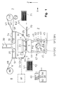
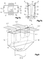
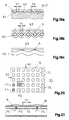
- Fig. 1 shows a flat embossing machine according to the invention for a embossing flat material 5, with a flat-flat press 2, with an embossing table 3 and as a counterpart a tool plate 4 with clichés 23 and with at least one embossing foil web 6.
- the flat material 5 to be embossed consists in this example of sheet 5.1, which from an investor 71 a register device 70 led to the flat embossing table 3, there at a standstill stamped and then stacked in a boom 72.
- Press is a toggle press 41 with four toggle lever pairs 43, with joints 44 and 45 and two pairs of tie rods 42.
- the tool plate 4 is adjustable in the Z direction by means of a positioning device 61, e.g.
- the embossing material is on one or more film webs 6, 6.1, 6.2 of unwinding rolls 7, 7.1, 7.2 via a first film loop store upstream of the press 10 and a film feed device 24 on one Side of the embossing table 3 and a clamping device 25 on the other side of the embossing table and then a film discharge device 8 fed.
- the film web 6 can be connected to the press via a second one Foil loop storage 20 on one or more winding rolls 80 are performed.
- Foil removal device 81 e.g. in the form of a compacting or shredding system, be used.
- the film feed device 24 is a precisely controllable slip-free feed of the film web 6, e.g. by means of lighter Rollers or suction elements, ensured while the tensioning device 25 an adjustable, optimal, even film tension on the embossing table generated, so that the film at the embossing location, smooth and without distortion and stretching for embossing is held at a standstill.
- the film feed device 24 is connected downstream of the press and the Tensioning device 25, e.g. as a precisely adjustable slip brake with constant Braking force or film tension, upstream of the press. It is the other way round also possible with a downstream tensioning device 25 a uniform Train to exert on the film web, which from an upstream Foil feed device is controlled precisely and without slippage (e.g. in Fig. 14).
- the flat embossing printing machine has a film feed and storage control 52 with an associated operating and display device 40.
- This feed control VV (t) must be carried out as gently, precisely and quickly as possible, so that the film web 6 is held precisely on the embossing table 3 during the printing phase TP (see FIG. 4) and then quickly and nevertheless gently into the during the unpressurized phase TL the next embossing position is brought forward.
- large, rapidly changing speed differences result between the relatively constant unwinding or winding speeds V7, V8 on the one hand and the intermittent feed speed VV (t).
- the accumulators are connected to a differential pressure device 30, which exerts an air pressure difference on the loops 12 in the accumulator and thus always keeps these loops smooth and stretched.
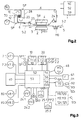
- FIG. 2 shows a flat embossing printing machine with a Endless web 5.2 as flat material 5 to be embossed with a dancer roller store 110, here the flat material and the film web 6 in the opposite direction are promoted, while Fig. 1 the advantageous in many cases Synchronization of flat material 5 and film web 6 illustrated.
- the film side Speed ratios with respect to VV, V7, V8 remain the same here same as described for Figure 1.
- the two film loop stores 10 and 20 are designed as a double labyrinth memory 28 with a common one internal suction as a differential pressure device 30. This represents a particularly simple and compact design of a double storage Measurement and monitoring of the loop depth LT and thus also the loop length L in the memories are film loop sensors SF (see FIG. 6).
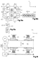
- FIG. 3 shows a circuit diagram with a machine control 50, a film web and storage control 52, and a control of the toggle lever geometry 54, a print control 56 and a register control 58 for sheet or for endless track machines 59, as well as with assigned sensors SF, SB, SP and SD and with an operating and display device 40 for those concerned Adjustment and control functions.
- the example illustrates the controls of one Machine with two independently controllable film webs 6.1, 6.2 with Unwinding rolls 7.1, 7.2 or winding rolls 80.1, 80.2 and associated sensors to determine the unwinding speed V7.1, V7.2 or the winding speed V8.1, V8.2 (e.g. determined from roller diameter and speed).
- the corresponding are also on the film feed devices 24.1, 24.2 Feed speeds VV1, VV2 determined (e.g. by means of Encoder on servo motors).
- VV1, VV2 Feed speeds
- the film tensioning devices 25.1, 25.2 optimal film tension forces FF1, FF2 directly or indirectly adjustable and controllable.
- These film clamping forces FF1, FF2 are on the film web in question and the chosen embossing process can be tuned to match the embossing foils on the one hand, as gently as possible and without overstretching, and on the other hand, nevertheless, a precise, stretched alignment and positioning the foils are reached at the embossing location 3, this and during the embossing process is optimally adjustable.
- An additional film-like alignment of the film webs 6 on the Clichés 23 of the tool plate 4 can be made using film image sensors SB1, SB2 take place (see Fig. 2 and 15a). This is e.g. required for embossing Holograms or foil images, which register to the clichés position (and from the other side the flat material is also the register device positioned with respect to the clichés).
- the foil and Memory controller 52 will also loop the two Stores 10 and 20 controlled and monitored, e.g. through film web sensors SF1.1, SF1.2 in memory 10 and sensors SF2.1, SF2.2 in memory 20, which each capture the loop depths LT1.1, LT1.2 and LT2.1, LT2.2.
- this film web and storage controller 52 can also control the toggle lever geometry as additional functions 54, e.g. by adjusting the distance XS between the toggle joint points and thus influencing the embossing time DT, and a control 56 of the Pressure force via the positioning device 61 of the press with the aid of pressure force sensors SP1 to SP4 (Fig. 1). Also a register control 58 for sheet machines with SDi sensors and actuators 91, 92, 93 (according to FIG. 1, 19) or a register control 59 for endless web machines with web memories 110, 120, web edge controls 112, 113 and web feed and Web tensioning devices 124, 125 result in an advantageous combination.
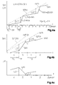
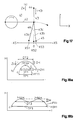
- FIG. 4 illustrates the feed control using an example with a five-cycle period VV, the film feed S (t) and the loop formation L (t) in the memories as a function of time over several embossing cycles. This is done here a relatively small film feed over four cycles (e.g. each 7 cm) and then a large feed in the fifth cycle (e.g. by 77 cm).
- FIG. 4b shows this course over the cycles 4, 5 and 1 in more detail.
- the feed S (t) is controlled as evenly as possible, without large changes in speed, ie with the lowest possible accelerations (d2S / dt 2 ). This is particularly important in the fifth cycle, when large changes in the loop length (from L2 to L1) occur in a short time during the depressurized phase TL of the cycle.
- the feed S (t) 0 must be during the printing phase TP and in particular during the embossing time DT, that is to say the film web must rest exactly on the embossing table.
- the line S7.2 (t) shows here, by way of example, a different time profile for a second film web 6.2, which here has a higher unwinding speed V7.2.
- FIG. 4c shows the change over time in the loop length L (t) in Foil loop memory 10 according to the feed movement S (t) according to Fig. 4b.
- FIG. 4d shows an enlarged feed S (t) in cycle 5 and the influence of the adjustment of the embossing time DT and thus also the pressure phase TP by a toggle lever adjustment according to FIGS. 16-18.
- a short embossing time DT1 a small value of TP1 results and remains accordingly a larger area TL1 for changing the feed speed VV and for changing the loop length L in the memories.
- the cycle time T0 and accordingly also the phases TP and TL become very small, which requires correspondingly higher feed speeds during the unpressurized phase TL.
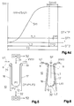
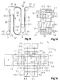
- the film loop 12 runs along the guide walls 16, 17 and parallel to these.
- the guide walls 16, 17 can e.g. also tapered the arrangement of guide walls (as well as any Side walls) and differential pressure devices so coordinated is that a uniform air flow for optimal training of the desired film loop in the entire area between minimum loop length L1 and maximum loop length L2 are created.
- the determination and The loop length L is monitored here with a distance sensor SF (e.g. as an optical or ultrasonic detector), which is at the memory input is arranged and measures the loop depth LT. Then from LT Loop length L can be calculated.
- a distance sensor SF e.g. as an optical or ultrasonic detector
- FIGS. 7a, b show a film loop memory with side walls 18, 19 from above and from the side.
- the example shows another variant of a adjustable memory geometry, with which, matched to the differential pressure device, an optimal local flow distribution for a perfect Loop formation, e.g. also of different widths of film, can be adjusted.
- With sliding side walls 18, 19 or lids 22 attached thereto may have adjustable openings or slots 13 are formed.
- the film loop memory according to FIG. 8 has one as another example Suction box 15 with an inlet opening 14 for the film webs 6.1, 6.2 and with a suction fan 32 at the loop end or at the lower end of the Suction box.
- the loop memory can simultaneously several film webs 6.1, 6.2 (different types and Width), which are independently promoted and thus form different loops. To achieve optimal flow conditions for each loop you can use the variable covers 26 approximately the same size free inlet openings on both sides of each film web 6.1, 6.2 27 can be set.
- the differential pressure devices can the film loop storage also suction rolls 34 or suction wall elements 35 with circumferential perforated bands 36, which are advantageous additionally combined with a pressure or suction fan 31, 32.
- FIG. 10 shows a suction roller 34 with a suction area 37 on the input side Promotion of the film web 6 into the memory.
- the loop formation is supported here by a pressure blower 31.
- a perforated suction wall element 35 conveys a rotating one Perforated tape 36 via the suction and conveying area 37 to the film web 6 Forming a loop in the memory.
- This memory is suitable e.g. particularly good for long loops with very narrow foil webs.
- FIG. 12 shows a suction wall element 35 with perforated band 36, the one running downwards Area 35.1 forms a transport wall of a feed store 10 and whose upward area 35.2 is a transport wall for a discharge store 20 forms.
- Figure 13 shows a double memory 29, which has two compartments 16.1, 17.1 and 16.2, 17.2, these two compartments having a plurality of film webs 6.1 to 6.4 alternately and each spaced apart among the subjects exhibit. Both compartments can be combined with only one differential pressure device operate.
- Figure 14 illustrates an example of a machine with multiple longitudinal and Transversal film webs (in the X and Y directions), which can be controlled independently are.
- Two longitudinal tracks 6.1 and 6.2 with feed speeds VV1, VV2 have separate feed devices 24.1, 24.2 and clamping devices 25.1, 25.2 and shared film loop storage 10.1, 20.1.
- Two Cross tracks 6.3, 6.4 with feed speeds VV3, VV4 have separate Feed devices 24.3, 24.4 and clamping devices 25.3, 25.4 and common film storage 10.2 and 20.2.
- FIG. 15 illustrates an embossing work with several different embossing foil webs with different embossed goods and different clichés, which is carried out simultaneously in one stamping process.
- the film webs in the longitudinal and transverse directions can be simultaneously with more clichés and more complex images.
- Condition is that no clichés are arranged in the crossing areas of the film webs are.
- a sheet 5.1 in to be embossed is shown in FIG. 15a Y direction divided into two identical areas.
- In the X direction with two identical film webs 6.1, 6.2 with image units corresponding to the Clichés 23.1 coined.
- FIG. 15b shows the pronounced image film web 6.2 and FIG. 15c the distinctive color film web 6.3 with a 3-cycle period.
- the order the film webs and their individual feed control is done in such a way that the foil stamping is used in the best possible way.
- a flat embossing printing machine is created, which is very demanding and complex embossing tasks in one pass at high speed and can perform in the best quality and also the film webs little burdened and whose embossed goods can be used in the best possible way.
- Figures 16-18 illustrate the combination of the inventive Machine with a geometry adjustment or an embossing time adjustment (DT).
- DT embossing time adjustment
- Figure 16 shows a geometry adjustment of a toggle press with seen from above four pairs of toggle levers, their lower four toggle lever joints 45 (see Figure 1) are adjusted simultaneously by a servo drive 48 via a Transmission to the four joints 45. The adjustment takes place e.g.
- each over one Spindle and an adjusting wedge 49 so that the distance XS of the joints 45 is adjustable by means of the controllable motors 48 and a geometry control 54.
- controllable motors 48 and a geometry control 54 there are also other forms of drive (e.g. hydraulic or with Manual drive) possible or all four joints 45 can be directly with one synchronously controlled motor can be moved.
- the adjustment can be programmable and is preferably done step by step only during the depressurized phase (TL).
- FIG. 17 illustrates the geometry adjustment on one of the toggle lever pairs 43, which are moved by the tie rods 42.
- the setting XS1 ⁇ 0 results in a maximum deflection position 43a, the toggle levers 43, 43a not fully reaching their elongated position 46.
- the setting XS2 0, the elongated length 46 is just reached in the maximum deflection position 43b.
- the setting XS3>0 the stretched length 46 is exceeded up to the maximum deflection 43c. This results in
- the height difference DH results from the extent to which a given flat material 5 to be embossed can be compressed. This also results in the course of the press pressure force F (t) corresponding to the stroke movement H (t). If in case a) the stretched position 46 is not completely reached, the tool plate 4 must be adjusted accordingly in the direction Z4 by means of the positioning device 61 in order to compensate for the missing height H.
- the embossing printing machine has sensors SP1 to SP4 for measuring the press pressure forces F (see FIGS. 1 and 16).
- the pressure control 56 controls the tool plate 4 in the direction Z4 by means of the positioning device 61, so that a desired predetermined working pressure F can be kept constant automatically.
- the pressure control can also contain various functions for controlling the pressure force.
- optimal parameter values can be set both with regard to the embossing time DT and with respect to the embossing pressure force F, and the highest embossing quality and machine performance can thus be achieved.
- This control of the toggle lever geometry and the printing phase can also be used to optimize the embossing quality independently of the loop stores according to the invention.
- films of various types and Widths can be processed optimally.
- very wide and very thin Foils with a thickness of e.g. 15 - 30 ⁇ are extremely difficult to work properly to transport.
- the insulating plastic carrier material of the foils is electrostatically charged, what on the guide walls (inlet walls 16 and Outlet walls 17) of the accumulator may have relatively high frictional forces can result, which lead to distortion and hull formation of the film webs can.
- An important development of the invention is the frictional forces of the foil webs running over it, especially on the inlet walls 16 to keep the loop storage small or to reduce it to one size, that the loop formation and the transport can take place optimally.
- FIGS. 19 to 23 Various Measures and means for this are shown in FIGS. 19 to 23 shown.
- the Ratio of contacted to covered area F1 / F0 is less than 50% and is preferably even less, e.g. 10 - 30%.
- Such structured surfaces 63 can be formed in various ways e.g. through grooves or channels 64, according to FIGS. 19 a and 20, or by means of grids or fine-mesh wire meshes 65 according to FIG. 91b or by perforated sheets, knobbed sheets or corrugated sheet 66 according to FIG. 19c.
- the lattice constant or the structural distances of these structured surfaces are preferably only 1mm or less, e.g. 0.3 - 1 mm.
- FIG. 20 shows a top view of an example of a structured surface with Longitudinal and transverse channels 64, here an area ratio F1 / F0 of approx. 25% is illustrated.
- FIG. 21 Another particularly simple and effective method for reducing the Contact area portion F1 or the frictional force of the film web on the inlet wall 16 consists of the film web by partially blowing in air partially detachable from the inlet wall.
- the Inlet wall 16 has injection holes 75 through which an overpressure chamber 74 local air is blown in under the film.
- This air-assisted Reduction of friction on the inlet wall is the one to be transported Corresponding foils, easy to dose by controlling the Overpressure P3 in the chambers 74. This can e.g. 2 - 4 bar.
- the Blow-off openings 75 are preferably dimensioned relatively small and large Spaced from each other. The diameter of the blow-off openings is e.g.
- the guide walls are metallically conductive and the ventilated inlet walls can be a smooth surface (Fig. 21) or a textured Surface (Fig.20).
- FIG. 22 shows a further variant for reducing the frictional force Applying a potential U2 to the inlet wall 16 with an adjustable one Voltage source 96.
- the inlet wall is metallically conductive and from the environment trained in isolation.
- the potential difference U1 - U2 between the film web 6 and the guide wall 16 reduced so far that the desired low value of the friction force is reached.
- the setting of the Potential U2 on the inlet wall 16 is such that an optimal smooth Loop formation and film guidance is achieved.
- the potential U1 of the film web 6 is determined by means of a capacitive potential probe 95 and then the potential U2 is set or regulated.
- FIG. 23 shows an example with a double compartment memory 29 before and after the embossing press and each with a film web 6.1, 6.2 in a respective compartment two double compartments.
- the loops are formed in the store by vacuum suction using a common suction fan 32.
- the four inlet walls 16.1, 16.2 have ventilation with overpressure chambers 74 with a pressure P3 and injection openings 75.
- the four outlet walls 17.1, 17.2 are, however, expressly not ventilated. The friction force the outlet walls are therefore deliberately higher than on the inlet walls, so that the film web is slightly stretched for perfect further transport becomes.
- a drag wheel 53 with a rotary encoder detects speed and Feed of the running film web, with which the motor of the winding roll 80 as well as feed and loop formation in the stores can be controlled.
- FIG. 24 shows the combination of the flat embossing printing machine according to the invention with a register control 58 of the flat material. That combination enables both-sided optimization on the film web side with regard to the Foil guidance and alignment as well as regarding the flat material guidance for precise image alignment.
- On the film side e.g. Film subjects like holograms or film images by means of the film image sensors SB (FIG. 15a, FIG. 2) precisely aligned with the clichés 23 on the tool plate 4, while the sheet 5.1 by the register control also in exact position the location of the clichés are aligned.
- Such register control for Sheet-fed machines are known from EP-A-708 046.
- the register feeding device 70 for flat embossing printing machines has leading edge stops, a side stop and position sensors SD1, SD2, SD3 for detecting print marks M1, M2, M3 of sheet 5.1 and two the detectors SD4, SD5 assigned to the front stops A1, A2 for Detect the leading edge of the sheet.
- the front stops are A1, A2 adjustable by actuators 91, 92 until the front print marks M1, M2 of the sheet are detected by the corresponding sensors SD1, SD2 are.
- An actuator 93 then adjusts the side stop or sideshift A3 until the page print mark M3 from the assigned position sensor SD3 is recorded.
- a register controller 58 controls this register correction with the position sensors SD1, SD2, SD3, the detectors SD4, SD5 and the actuators 91, 92, 93. This simply results in a reliable automatic register correction for each individual sheet and increased thus, in combination with the film guidance and control, the print quality.
- FIG. 25 shows, seen from above, a register control 59 for Endless web machines (Fig. 2) with sensors SD1, SD3 for detecting Print marks M1, M3.
- the endless web 5.2 runs from an unwind roll 107 to a take-up reel 108 with web edge controls 112, 113, web stores 110, 120 (designed as dancer rollers or also as a suction accumulator), a web tensioning device 125 and a web feed device 124
- the continuous web is aligned in the transverse direction Y with the print mark M3 through the known web edge controls 112, 113 and Alignment with the mark M1 in the longitudinal direction X is carried out with the web feed device 124 controlled.
- Foil web control also here web storage 110 and 120 for the endless web 5.2 used.
Applications Claiming Priority (3)
| Application Number | Priority Date | Filing Date | Title |
|---|---|---|---|
| CH31297 | 1997-02-13 | ||
| CH312/97 | 1997-02-13 | ||
| CH31297 | 1997-02-13 |
Publications (4)
| Publication Number | Publication Date |
|---|---|
| EP0858888A2 true EP0858888A2 (fr) | 1998-08-19 |
| EP0858888A3 EP0858888A3 (fr) | 1999-02-17 |
| EP0858888B1 EP0858888B1 (fr) | 2002-09-11 |
| EP0858888B2 EP0858888B2 (fr) | 2007-03-07 |
Family
ID=4184142
Family Applications (1)
| Application Number | Title | Priority Date | Filing Date |
|---|---|---|---|
| EP98101498A Expired - Lifetime EP0858888B2 (fr) | 1997-02-13 | 1998-01-29 | Presse d'estampage à plat |
Country Status (3)
| Country | Link |
|---|---|
| US (1) | US5979308A (fr) |
| EP (1) | EP0858888B2 (fr) |
| DE (1) | DE59805462D1 (fr) |
Cited By (21)
| Publication number | Priority date | Publication date | Assignee | Title |
|---|---|---|---|---|
| EP0987205A1 (fr) * | 1998-09-17 | 2000-03-22 | Armin Steuer | Accumulateur à boucle pour matériau en bande et son utilisation |
| WO2000064794A1 (fr) * | 1999-04-23 | 2000-11-02 | Schober Gmbh | Dispositif pour appliquer des elements delimites spatialement, en particulier souples |
| NL1013194C2 (nl) * | 1999-10-01 | 2001-04-03 | Aremberg Beheer B V I O | Werkwijze voor het bufferen van bandmateriaal, toevoerinrichting voor bandmateriaal en inrichting voor het met bandmateriaal omgeven van producten. |
| EP1593503A3 (fr) * | 2004-05-04 | 2006-07-26 | Maschinenfabrik Gietz Ag | Dispostif de guidage du film d'une machine de dorure à plat |
| FR2913914A1 (fr) * | 2007-03-21 | 2008-09-26 | Cer Soc Par Actions Simplifiee | Machine de marquage a ruban |
| WO2009150029A1 (fr) * | 2008-05-28 | 2009-12-17 | Manroland Ag | Dispositif de gaufrage de feuilles à froid |
| WO2011042047A1 (fr) * | 2009-10-06 | 2011-04-14 | Kern Ag | Dispositif pour couper des bandes de papier |
| CN102169814A (zh) * | 2010-02-03 | 2011-08-31 | 志圣工业股份有限公司 | 晶圆压膜机离形膜保护机构 |
| CN102491112A (zh) * | 2011-12-01 | 2012-06-13 | 陈晓滨 | 纸张输送机构 |
| CN102896890A (zh) * | 2011-07-27 | 2013-01-30 | 上海亚华印刷机械有限公司 | 一种具备铝箔储存装置的烫印机 |
| EP2578405A1 (fr) * | 2011-10-07 | 2013-04-10 | Komori Corporation | Appareil de transfert de film |
| WO2016086325A1 (fr) * | 2014-12-04 | 2016-06-09 | Gietz Ag | Machine d'impression par gaufrage avec guidage de bande de film et de feuille |
| WO2017031603A2 (fr) | 2015-08-21 | 2017-03-02 | Gietz Ag | Machine d'estampage à plat |
| EP3173232A1 (fr) | 2015-11-30 | 2017-05-31 | KBA-NotaSys SA | Presse à estamper à chaud |
| WO2019200596A1 (fr) * | 2018-04-20 | 2019-10-24 | Bobst Mex Sa | Dispositif d'entraînement d'une feuille d'estampage, station et machine d'estampage, et procédé de commande de l'entraînement d'une feuille d'estampage |
| CN111231503A (zh) * | 2019-10-09 | 2020-06-05 | 上海灵博塑料包装有限公司 | 一种薄膜在线烫金机 |
| US10737485B2 (en) | 2015-11-05 | 2020-08-11 | Kba-Notasys Sa | Sheet-fed stamping press comprising a foil laminating unit |
| US10800159B2 (en) | 2015-01-27 | 2020-10-13 | Illinois Tool Works Inc. | Marking machine and method for implementing such a machine |
| US11065865B2 (en) | 2015-11-05 | 2021-07-20 | Kba-Notasys Sa | Sheet-fed stamping press having a foil laminating unit |
| CN115256903A (zh) * | 2022-06-22 | 2022-11-01 | 中化工程沧州冷却技术有限公司 | 一种填料用的压花成型装置 |
| WO2023148250A1 (fr) | 2022-02-02 | 2023-08-10 | Gietz Ag | Machine d'impression par estampage à plat comprenant un dispositif de guidage et de transport de bande de film |
Families Citing this family (26)
| Publication number | Priority date | Publication date | Assignee | Title |
|---|---|---|---|---|
| US6606942B2 (en) * | 2001-02-26 | 2003-08-19 | Armin Steuer | Die stamping method and die stamping device |
| DE10148975A1 (de) * | 2001-10-04 | 2003-04-10 | Zahoransky Anton Gmbh & Co | Verfahren und Vorrichtung zum Bedrucken von Gegenständen |
| DE10236597A1 (de) * | 2002-08-09 | 2004-02-19 | Leonhard Kurz Gmbh & Co. Kg | Laserunterstütztes Replizierverfahren |
| US7012232B1 (en) | 2004-08-31 | 2006-03-14 | Mark Gruenspecht | RF welding device |
| DE602006016414D1 (de) * | 2005-03-29 | 2010-10-07 | Concepts For Success | Verfahren und einrichtung zur herstellung von dreidimensional geformten oder mit gürtel ausgestatteten artikeln, wie zum beispiel kleidungsstücken oder absorbierenden artikeln |
| US20060219108A1 (en) * | 2005-04-01 | 2006-10-05 | Dorrell Cheryl B | Apparatus and method for production of personalized gift-wrap |
| US20070044921A1 (en) * | 2005-08-31 | 2007-03-01 | Laser Die And Engineering | Apparatus for applying heat/pressure-activated labels to pre-formed automotive interior panels |
| DE102007049421B4 (de) * | 2007-10-12 | 2010-06-10 | Leonhard Kurz Gmbh & Co. Kg | Verfahren und Vorrichtung zur Dekoration einer Oberfläche eines Werkstücks |
| DE102008011493A1 (de) * | 2008-02-20 | 2009-08-27 | Spm Steuer Gmbh & Co. Kg | Verfahren zur Entsorgung von verbrauchter Prägefolienbahn sowie Prägevorrichtung mit kontinuierlich arbeitender Entsorgungseinrichtung |
| JP2009208308A (ja) * | 2008-03-03 | 2009-09-17 | Miyakoshi Printing Machinery Co Ltd | 箔転写装置 |
| EP2285720B1 (fr) * | 2008-05-27 | 2015-09-02 | Gietz AG | Machine d'impression-gaufrage à plat pourvue d'un dispositif de guidage de feuilles continues |
| JP4829364B1 (ja) * | 2010-05-25 | 2011-12-07 | トタニ技研工業株式会社 | 製袋機 |
| KR101459251B1 (ko) * | 2010-09-08 | 2014-11-07 | 봅스트 맥스 에스에이 | 스트립을 이동시키는 시스템 내에서 엠보싱될 스트립을 공급하는 방법 및 이러한 방법을 실행하는 장치 |
| TWI515120B (zh) * | 2010-09-22 | 2016-01-01 | 巴柏斯特合資公司 | 包含平板壓機的打印機 |
| CN103391892A (zh) * | 2011-02-28 | 2013-11-13 | 鲍勃斯脱梅克斯股份有限公司 | 印压机的带展开装置 |
| CN103373051B (zh) * | 2012-04-28 | 2015-11-18 | 上海旭恒精工机械制造有限公司 | 保压时间可调的模切/烫印平台驱动机构 |
| CN104129155A (zh) * | 2014-07-25 | 2014-11-05 | 上海达盾自动化科技有限公司 | 一种铝箔烫印机 |
| CN105729998B (zh) * | 2016-04-19 | 2018-10-26 | 唐山瑞可达科技有限公司 | 平压平烫金模切机运动平台调整装置 |
| CN106393963B (zh) * | 2016-08-31 | 2018-08-24 | 瑞安市飞鹏机械厂 | 全自动平压平压痕烫金设备 |
| DE102017118934A1 (de) * | 2017-07-03 | 2019-01-03 | Weber Maschinenbau Gmbh Breidenbach | Bereitstellen von bahnförmigem Zwischenblattmaterial an einem Schneidbereich |
| DE102017118927A1 (de) * | 2017-07-03 | 2019-01-03 | Weber Maschinenbau Gmbh Breidenbach | Bereitstellen von bahnförmigem Zwischenblattmaterial an einem Schneidbereich |
| EP3888467A1 (fr) * | 2017-07-03 | 2021-10-06 | Weber Maschinenbau GmbH Breidenbach | Production de matériau intermédiaire sous forme de feuille en bande sur une zone de coupe |
| DE102017118925A1 (de) * | 2017-07-03 | 2019-01-03 | Weber Maschinenbau Gmbh Breidenbach | Bereitstellen von bahnförmigem Zwischenblattmaterial an einem Schneidbereich |
| PL3424852T3 (pl) * | 2017-07-03 | 2021-11-02 | Weber Maschinenbau Gmbh Breidenbach | Dostarczanie pasmowego materiału przekładkowego do obszaru cięcia |
| DE102017118930A1 (de) * | 2017-07-03 | 2019-01-03 | Weber Maschinenbau Gmbh Breidenbach | Bereitstellen von bahnförmigem Zwischenblattmaterial an einem Schneidbereich |
| CN107522005B (zh) * | 2017-09-22 | 2024-02-06 | 天津长荣科技集团股份有限公司 | 一种下吸式递纸装置 |
Citations (10)
| Publication number | Priority date | Publication date | Assignee | Title |
|---|---|---|---|---|
| DE881517C (de) * | 1946-02-01 | 1953-07-02 | George Ernest Packer | Praegedruck mittels beheizter Praegedruckform und Tiegel |
| US5079569A (en) * | 1991-02-25 | 1992-01-07 | B. Bunch Company, Inc. | Laser printer with paper positioning and tensioning features |
| GB2249782A (en) * | 1990-11-19 | 1992-05-20 | Tokyo Automatic Mach Works | Web feeding mechanism |
| GB2254586A (en) * | 1991-04-11 | 1992-10-14 | Profoil Systems Limited | Foil blocking apparatus |
| EP0623432A1 (fr) * | 1993-04-08 | 1994-11-09 | Eastman Kodak Company | Dispositif et méthode pour le transport et la perforation d'une bande de matériau |
| EP0658505A1 (fr) * | 1993-12-16 | 1995-06-21 | Eastman Kodak Company | Caisse aspirante sans contact et procédé d'opération |
| EP0690017A2 (fr) * | 1994-06-30 | 1996-01-03 | Eastman Kodak Company | Appareil à faible inertie et procédé pour accumuler et appliquer une tension à des bandes |
| EP0708046A1 (fr) * | 1994-10-21 | 1996-04-24 | Maschinenfabrik Gietz Ag | Dispositif de répérage et d'alimentation de feuilles |
| EP0723925A2 (fr) * | 1995-01-26 | 1996-07-31 | Japan Tobacco Inc. | Appareil pour le transfert stable de matériau en forme de bande |
| EP0741001A2 (fr) * | 1995-05-04 | 1996-11-06 | Gietz AG | Estampeuse, imprimeuse et poinçonneuse |
Family Cites Families (9)
| Publication number | Priority date | Publication date | Assignee | Title |
|---|---|---|---|---|
| US1558156A (en) * | 1918-05-02 | 1925-10-20 | Duratex Corp | Fabric-delivering mechanism for embossing presses |
| US3584572A (en) * | 1968-02-19 | 1971-06-15 | Anthony Apicella | Method, apparatus and die adapted to simultaneously heat stamp, emboss and cut |
| US4218026A (en) * | 1978-06-23 | 1980-08-19 | Xerox Corporation | Paper web buffer system |
| US4253597A (en) * | 1979-07-09 | 1981-03-03 | Moore Business Forms, Inc. | Loose loop feed control apparatus |
| CH674337A5 (fr) * | 1987-04-08 | 1990-05-31 | Gietz Ag Maschf | |
| US5448419A (en) * | 1993-06-11 | 1995-09-05 | Eastman Kodak Company | Apparatus and method for anhysteretically recording from master drum to slave web |
| DE9420707U1 (de) * | 1994-12-24 | 1995-02-16 | Steuer Armin | Präge-Rotationsmaschine |
| DE19503110B4 (de) * | 1995-02-01 | 2009-01-29 | Heidelberger Druckmaschinen Ag | Bogenleiteinrichtung für Druckmaschinen |
| US5813337A (en) * | 1996-06-05 | 1998-09-29 | Quad/Tech, Inc. | Closed-loop printing control system |
-
1998
- 1998-01-29 DE DE59805462T patent/DE59805462D1/de not_active Expired - Lifetime
- 1998-01-29 EP EP98101498A patent/EP0858888B2/fr not_active Expired - Lifetime
- 1998-02-11 US US09/021,757 patent/US5979308A/en not_active Expired - Lifetime
Patent Citations (10)
| Publication number | Priority date | Publication date | Assignee | Title |
|---|---|---|---|---|
| DE881517C (de) * | 1946-02-01 | 1953-07-02 | George Ernest Packer | Praegedruck mittels beheizter Praegedruckform und Tiegel |
| GB2249782A (en) * | 1990-11-19 | 1992-05-20 | Tokyo Automatic Mach Works | Web feeding mechanism |
| US5079569A (en) * | 1991-02-25 | 1992-01-07 | B. Bunch Company, Inc. | Laser printer with paper positioning and tensioning features |
| GB2254586A (en) * | 1991-04-11 | 1992-10-14 | Profoil Systems Limited | Foil blocking apparatus |
| EP0623432A1 (fr) * | 1993-04-08 | 1994-11-09 | Eastman Kodak Company | Dispositif et méthode pour le transport et la perforation d'une bande de matériau |
| EP0658505A1 (fr) * | 1993-12-16 | 1995-06-21 | Eastman Kodak Company | Caisse aspirante sans contact et procédé d'opération |
| EP0690017A2 (fr) * | 1994-06-30 | 1996-01-03 | Eastman Kodak Company | Appareil à faible inertie et procédé pour accumuler et appliquer une tension à des bandes |
| EP0708046A1 (fr) * | 1994-10-21 | 1996-04-24 | Maschinenfabrik Gietz Ag | Dispositif de répérage et d'alimentation de feuilles |
| EP0723925A2 (fr) * | 1995-01-26 | 1996-07-31 | Japan Tobacco Inc. | Appareil pour le transfert stable de matériau en forme de bande |
| EP0741001A2 (fr) * | 1995-05-04 | 1996-11-06 | Gietz AG | Estampeuse, imprimeuse et poinçonneuse |
Cited By (39)
| Publication number | Priority date | Publication date | Assignee | Title |
|---|---|---|---|---|
| EP0987205A1 (fr) * | 1998-09-17 | 2000-03-22 | Armin Steuer | Accumulateur à boucle pour matériau en bande et son utilisation |
| WO2000064794A1 (fr) * | 1999-04-23 | 2000-11-02 | Schober Gmbh | Dispositif pour appliquer des elements delimites spatialement, en particulier souples |
| US6616026B1 (en) | 1999-04-23 | 2003-09-09 | Schober Gmbh Werkzeug- Und Maschinenbau | Device for applying spatially limited elements, in particular, flexible elements |
| NL1013194C2 (nl) * | 1999-10-01 | 2001-04-03 | Aremberg Beheer B V I O | Werkwijze voor het bufferen van bandmateriaal, toevoerinrichting voor bandmateriaal en inrichting voor het met bandmateriaal omgeven van producten. |
| EP1593503A3 (fr) * | 2004-05-04 | 2006-07-26 | Maschinenfabrik Gietz Ag | Dispostif de guidage du film d'une machine de dorure à plat |
| US8074568B2 (en) | 2007-03-21 | 2011-12-13 | Cer | Foil stamping machine |
| FR2913914A1 (fr) * | 2007-03-21 | 2008-09-26 | Cer Soc Par Actions Simplifiee | Machine de marquage a ruban |
| WO2008142225A2 (fr) * | 2007-03-21 | 2008-11-27 | Cer | Machine de marquage a ruban |
| WO2008142225A3 (fr) * | 2007-03-21 | 2009-02-19 | Cer | Machine de marquage a ruban |
| WO2009150029A1 (fr) * | 2008-05-28 | 2009-12-17 | Manroland Ag | Dispositif de gaufrage de feuilles à froid |
| CN102046382B (zh) * | 2008-05-28 | 2013-07-24 | 曼罗兰纸张有限责任公司 | 用于冷薄膜压印的装置 |
| CN102639418B (zh) * | 2009-10-06 | 2015-08-12 | 科恩股份公司 | 用于切割纸带的装置 |
| US10106356B2 (en) | 2009-10-06 | 2018-10-23 | Kern Ag | Device for cutting paper webs |
| CN102639418A (zh) * | 2009-10-06 | 2012-08-15 | 科恩股份公司 | 用于切割纸带的装置 |
| WO2011042047A1 (fr) * | 2009-10-06 | 2011-04-14 | Kern Ag | Dispositif pour couper des bandes de papier |
| CN102169814B (zh) * | 2010-02-03 | 2013-05-22 | 志圣工业股份有限公司 | 晶圆压膜机离形膜保护机构 |
| CN102169814A (zh) * | 2010-02-03 | 2011-08-31 | 志圣工业股份有限公司 | 晶圆压膜机离形膜保护机构 |
| CN102896890A (zh) * | 2011-07-27 | 2013-01-30 | 上海亚华印刷机械有限公司 | 一种具备铝箔储存装置的烫印机 |
| EP2578405A1 (fr) * | 2011-10-07 | 2013-04-10 | Komori Corporation | Appareil de transfert de film |
| US9278508B2 (en) | 2011-10-07 | 2016-03-08 | Komori Corporation | Film transfer apparatus |
| CN102491112A (zh) * | 2011-12-01 | 2012-06-13 | 陈晓滨 | 纸张输送机构 |
| US10525763B2 (en) | 2014-12-04 | 2020-01-07 | Gietz Ag | Flat foil printing press having foil web and sheet guidance |
| WO2016086325A1 (fr) * | 2014-12-04 | 2016-06-09 | Gietz Ag | Machine d'impression par gaufrage avec guidage de bande de film et de feuille |
| US10800159B2 (en) | 2015-01-27 | 2020-10-13 | Illinois Tool Works Inc. | Marking machine and method for implementing such a machine |
| WO2017031603A2 (fr) | 2015-08-21 | 2017-03-02 | Gietz Ag | Machine d'estampage à plat |
| US11065865B2 (en) | 2015-11-05 | 2021-07-20 | Kba-Notasys Sa | Sheet-fed stamping press having a foil laminating unit |
| US10737485B2 (en) | 2015-11-05 | 2020-08-11 | Kba-Notasys Sa | Sheet-fed stamping press comprising a foil laminating unit |
| EP3173232A1 (fr) | 2015-11-30 | 2017-05-31 | KBA-NotaSys SA | Presse à estamper à chaud |
| WO2017093894A1 (fr) | 2015-11-30 | 2017-06-08 | Kba-Notasys Sa | Presse à marquer à chaud |
| US11697277B2 (en) | 2015-11-30 | 2023-07-11 | Kba-Notsys Sa | Hot-stamping press |
| CN111989220B (zh) * | 2018-04-20 | 2022-07-29 | 鲍勃斯脱梅克斯股份有限公司 | 压印箔的驱动装置,压印站和压印机及控制压印箔的驱动的方法 |
| CN111989220A (zh) * | 2018-04-20 | 2020-11-24 | 鲍勃斯脱梅克斯股份有限公司 | 压印箔的驱动装置,压印站和压印机及控制压印箔的驱动的方法 |
| US11325408B2 (en) | 2018-04-20 | 2022-05-10 | Bobst Mex Sa | Device for driving a stamping foil, stamping station and machine, and method for controlling the driving of a stamping foil |
| WO2019200596A1 (fr) * | 2018-04-20 | 2019-10-24 | Bobst Mex Sa | Dispositif d'entraînement d'une feuille d'estampage, station et machine d'estampage, et procédé de commande de l'entraînement d'une feuille d'estampage |
| CN111231503A (zh) * | 2019-10-09 | 2020-06-05 | 上海灵博塑料包装有限公司 | 一种薄膜在线烫金机 |
| WO2023148250A1 (fr) | 2022-02-02 | 2023-08-10 | Gietz Ag | Machine d'impression par estampage à plat comprenant un dispositif de guidage et de transport de bande de film |
| CH719395A1 (de) * | 2022-02-02 | 2023-08-15 | Gietz Ag | Flachprägedruckmaschine mit einer Folienbahnführungs- und Transporteinrichtung. |
| CN115256903A (zh) * | 2022-06-22 | 2022-11-01 | 中化工程沧州冷却技术有限公司 | 一种填料用的压花成型装置 |
| CN115256903B (zh) * | 2022-06-22 | 2023-06-16 | 中化工程沧州冷却技术有限公司 | 一种填料用的压花成型装置 |
Also Published As
| Publication number | Publication date |
|---|---|
| EP0858888B2 (fr) | 2007-03-07 |
| EP0858888B1 (fr) | 2002-09-11 |
| DE59805462D1 (de) | 2002-10-17 |
| EP0858888A3 (fr) | 1999-02-17 |
| US5979308A (en) | 1999-11-09 |
Similar Documents
| Publication | Publication Date | Title |
|---|---|---|
| EP0858888B1 (fr) | Presse d'estampage à plat | |
| EP0987205B1 (fr) | Accumulateur à boucle pour matériau en bande et son utilisation | |
| EP1790601B1 (fr) | Contrôle de la tension d'une bande de matériau | |
| EP1457324B1 (fr) | Procédé et dispositif pour imprimer une bande | |
| DE102009020106B4 (de) | Folientaktung | |
| EP1556301B1 (fr) | Dispositifs pour traiter et/ou acheminer une bande de matiere | |
| EP0475095A1 (fr) | Dispositif d'alignement d'une bande continue par rapport à une deuxième bande | |
| WO2002022368A1 (fr) | Dispositif d'impression a jet d'encre | |
| EP0744365B1 (fr) | Méthode pour changer le rouleau dans une machine à enrouler et machine à enrouler pour l'application de cette méthode | |
| DE3713666C2 (de) | Verfahren zum Aufprägen und Präge-Rotationsmaschine | |
| EP1815982B1 (fr) | Guidage de film dans un dispositif d'estampage | |
| EP2841365B1 (fr) | Système d'acheminement par aspiration pour le transport d'éléments plats et installation pour la fabrication d'éléments plats comprenant ledit système | |
| DE102014104662B4 (de) | Arbeitsverfahren für den digitalen Multipass-Mehrfarbendruck | |
| EP0518053B1 (fr) | Procédé et appareil pour la fabrication de carton ondulé imprimé de grande largeur | |
| EP1155831B1 (fr) | Procédé et dispositif d'estampage à chaud. | |
| EP2128060B1 (fr) | Machine d'estampage de feuilles | |
| DE2111160A1 (de) | Vorrichtung fuer die Befoerderung von metallisierten Baendern in einer Plattenpresse | |
| EP3737630B1 (fr) | Arrangement pour découper une bande de matière en feuilles individuelles avec un accumulateur de bande | |
| DE102006023825A1 (de) | Verfahren und System zur Antriebsregelung einer Druck- und/oder Verarbeitungsmaschine | |
| DE3616664C2 (de) | Einrichtung zum Abtrennen von einzelnen Bahnabschnitten aus einer Bahn, die durch einzelne aufeinanderfolgend auf eine Kunststoffilmbahn aufkaschierte Flächenelemente gebildet ist | |
| DE102008042902B4 (de) | Bogenbremse einer Druckmaschine und Verfahren zum Antrieb einer Bogenbremse | |
| DE3744107A1 (de) | Einrichtung zur herstellung von querlinien an materialbahnen | |
| DE4137369A1 (de) | Bandspannvorrichtung | |
| WO2021083676A1 (fr) | Machine de traitement de feuilles avec au moins un dispositif de stockage de feuilles et procédé de stockage de feuilles | |
| DE10009162A1 (de) | Folienprägemaschine |
Legal Events
| Date | Code | Title | Description |
|---|---|---|---|
| PUAI | Public reference made under article 153(3) epc to a published international application that has entered the european phase |
Free format text: ORIGINAL CODE: 0009012 |
|
| AK | Designated contracting states |
Kind code of ref document: A2 Designated state(s): CH DE GB LI |
|
| AX | Request for extension of the european patent |
Free format text: AL;LT;LV;MK;RO;SI |
|
| PUAL | Search report despatched |
Free format text: ORIGINAL CODE: 0009013 |
|
| AK | Designated contracting states |
Kind code of ref document: A3 Designated state(s): AT BE CH DE DK ES FI FR GB GR IE IT LI LU MC NL PT SE |
|
| AX | Request for extension of the european patent |
Free format text: AL;LT;LV;MK;RO;SI |
|
| 17P | Request for examination filed |
Effective date: 19990722 |
|
| AKX | Designation fees paid |
Free format text: CH DE GB LI |
|
| 17Q | First examination report despatched |
Effective date: 19990924 |
|
| GRAG | Despatch of communication of intention to grant |
Free format text: ORIGINAL CODE: EPIDOS AGRA |
|
| GRAG | Despatch of communication of intention to grant |
Free format text: ORIGINAL CODE: EPIDOS AGRA |
|
| GRAG | Despatch of communication of intention to grant |
Free format text: ORIGINAL CODE: EPIDOS AGRA |
|
| GRAH | Despatch of communication of intention to grant a patent |
Free format text: ORIGINAL CODE: EPIDOS IGRA |
|
| GRAH | Despatch of communication of intention to grant a patent |
Free format text: ORIGINAL CODE: EPIDOS IGRA |
|
| GRAA | (expected) grant |
Free format text: ORIGINAL CODE: 0009210 |
|
| AK | Designated contracting states |
Kind code of ref document: B1 Designated state(s): CH DE GB LI |
|
| REG | Reference to a national code |
Ref country code: GB Ref legal event code: FG4D Free format text: NOT ENGLISH |
|
| REG | Reference to a national code |
Ref country code: CH Ref legal event code: EP |
|
| REF | Corresponds to: |
Ref document number: 59805462 Country of ref document: DE Date of ref document: 20021017 |
|
| REG | Reference to a national code |
Ref country code: CH Ref legal event code: NV Representative=s name: FREI PATENTANWALTSBUERO |
|
| GBT | Gb: translation of ep patent filed (gb section 77(6)(a)/1977) |
Effective date: 20021205 |
|
| PLBI | Opposition filed |
Free format text: ORIGINAL CODE: 0009260 |
|
| PLAX | Notice of opposition and request to file observation + time limit sent |
Free format text: ORIGINAL CODE: EPIDOSNOBS2 |
|
| PLBQ | Unpublished change to opponent data |
Free format text: ORIGINAL CODE: EPIDOS OPPO |
|
| PLAB | Opposition data, opponent's data or that of the opponent's representative modified |
Free format text: ORIGINAL CODE: 0009299OPPO |
|
| 26 | Opposition filed |
Opponent name: BOBST S.A. Effective date: 20030611 |
|
| R26 | Opposition filed (corrected) |
Opponent name: BOBST S.A. Effective date: 20030611 |
|
| PLAX | Notice of opposition and request to file observation + time limit sent |
Free format text: ORIGINAL CODE: EPIDOSNOBS2 |
|
| PLBB | Reply of patent proprietor to notice(s) of opposition received |
Free format text: ORIGINAL CODE: EPIDOSNOBS3 |
|
| APBP | Date of receipt of notice of appeal recorded |
Free format text: ORIGINAL CODE: EPIDOSNNOA2O |
|
| APAH | Appeal reference modified |
Free format text: ORIGINAL CODE: EPIDOSCREFNO |
|
| PLAB | Opposition data, opponent's data or that of the opponent's representative modified |
Free format text: ORIGINAL CODE: 0009299OPPO |
|
| R26 | Opposition filed (corrected) |
Opponent name: BOBST S.A. Effective date: 20030611 |
|
| APBU | Appeal procedure closed |
Free format text: ORIGINAL CODE: EPIDOSNNOA9O |
|
| PUAH | Patent maintained in amended form |
Free format text: ORIGINAL CODE: 0009272 |
|
| STAA | Information on the status of an ep patent application or granted ep patent |
Free format text: STATUS: PATENT MAINTAINED AS AMENDED |
|
| 27A | Patent maintained in amended form |
Effective date: 20070307 |
|
| AK | Designated contracting states |
Kind code of ref document: B2 Designated state(s): CH DE GB LI |
|
| REG | Reference to a national code |
Ref country code: CH Ref legal event code: AEN Free format text: AUFRECHTERHALTUNG DES PATENTES IN GEAENDERTER FORM |
|
| GBTA | Gb: translation of amended ep patent filed (gb section 77(6)(b)/1977) | ||
| PGFP | Annual fee paid to national office [announced via postgrant information from national office to epo] |
Ref country code: DE Payment date: 20170120 Year of fee payment: 20 Ref country code: CH Payment date: 20170113 Year of fee payment: 20 |
|
| PGFP | Annual fee paid to national office [announced via postgrant information from national office to epo] |
Ref country code: GB Payment date: 20170119 Year of fee payment: 20 |
|
| REG | Reference to a national code |
Ref country code: DE Ref legal event code: R071 Ref document number: 59805462 Country of ref document: DE |
|
| REG | Reference to a national code |
Ref country code: CH Ref legal event code: PL |
|
| REG | Reference to a national code |
Ref country code: GB Ref legal event code: PE20 Expiry date: 20180128 |
|
| PG25 | Lapsed in a contracting state [announced via postgrant information from national office to epo] |
Ref country code: GB Free format text: LAPSE BECAUSE OF EXPIRATION OF PROTECTION Effective date: 20180128 |