EP0858888A2 - Flat-bed blocking press - Google Patents
Flat-bed blocking press Download PDFInfo
- Publication number
- EP0858888A2 EP0858888A2 EP98101498A EP98101498A EP0858888A2 EP 0858888 A2 EP0858888 A2 EP 0858888A2 EP 98101498 A EP98101498 A EP 98101498A EP 98101498 A EP98101498 A EP 98101498A EP 0858888 A2 EP0858888 A2 EP 0858888A2
- Authority
- EP
- European Patent Office
- Prior art keywords
- film
- printing machine
- machine according
- loop
- flat
- Prior art date
- Legal status (The legal status is an assumption and is not a legal conclusion. Google has not performed a legal analysis and makes no representation as to the accuracy of the status listed.)
- Granted
Links
Images


Classifications
-
- B—PERFORMING OPERATIONS; TRANSPORTING
- B65—CONVEYING; PACKING; STORING; HANDLING THIN OR FILAMENTARY MATERIAL
- B65H—HANDLING THIN OR FILAMENTARY MATERIAL, e.g. SHEETS, WEBS, CABLES
- B65H20/00—Advancing webs
- B65H20/30—Arrangements for accumulating surplus web
- B65H20/32—Arrangements for accumulating surplus web by making loops
-
- B—PERFORMING OPERATIONS; TRANSPORTING
- B41—PRINTING; LINING MACHINES; TYPEWRITERS; STAMPS
- B41F—PRINTING MACHINES OR PRESSES
- B41F19/00—Apparatus or machines for carrying out printing operations combined with other operations
- B41F19/02—Apparatus or machines for carrying out printing operations combined with other operations with embossing
- B41F19/06—Printing and embossing between a negative and a positive forme after inking and wiping the negative forme; Printing from an ink band treated with colour or "gold"
- B41F19/064—Presses of the reciprocating type
- B41F19/068—Presses of the reciprocating type motor-driven
-
- B—PERFORMING OPERATIONS; TRANSPORTING
- B41—PRINTING; LINING MACHINES; TYPEWRITERS; STAMPS
- B41P—INDEXING SCHEME RELATING TO PRINTING, LINING MACHINES, TYPEWRITERS, AND TO STAMPS
- B41P2219/00—Printing presses using a heated printing foil
- B41P2219/10—Driving devices for the reciprocating die
- B41P2219/13—Gearings
- B41P2219/134—Knee-lever
-
- B—PERFORMING OPERATIONS; TRANSPORTING
- B41—PRINTING; LINING MACHINES; TYPEWRITERS; STAMPS
- B41P—INDEXING SCHEME RELATING TO PRINTING, LINING MACHINES, TYPEWRITERS, AND TO STAMPS
- B41P2219/00—Printing presses using a heated printing foil
- B41P2219/20—Arrangements for moving, supporting or positioning the printing foil
-
- B—PERFORMING OPERATIONS; TRANSPORTING
- B41—PRINTING; LINING MACHINES; TYPEWRITERS; STAMPS
- B41P—INDEXING SCHEME RELATING TO PRINTING, LINING MACHINES, TYPEWRITERS, AND TO STAMPS
- B41P2219/00—Printing presses using a heated printing foil
- B41P2219/40—Material or products to be decorated or printed
- B41P2219/42—Sheet-like material
-
- B—PERFORMING OPERATIONS; TRANSPORTING
- B65—CONVEYING; PACKING; STORING; HANDLING THIN OR FILAMENTARY MATERIAL
- B65H—HANDLING THIN OR FILAMENTARY MATERIAL, e.g. SHEETS, WEBS, CABLES
- B65H2406/00—Means using fluid
- B65H2406/30—Suction means
- B65H2406/31—Suction box; Suction chambers
- B65H2406/311—Suction box; Suction chambers for accumulating a loop of handled material
-
- B—PERFORMING OPERATIONS; TRANSPORTING
- B65—CONVEYING; PACKING; STORING; HANDLING THIN OR FILAMENTARY MATERIAL
- B65H—HANDLING THIN OR FILAMENTARY MATERIAL, e.g. SHEETS, WEBS, CABLES
- B65H2408/00—Specific machines
- B65H2408/20—Specific machines for handling web(s)
- B65H2408/21—Accumulators
- B65H2408/215—Accumulators supported by vacuum or blown air
Definitions
- the invention relates to a flat embossing printing machine for a to be embossed Flat material with a flat press, embossing table and tool plate according to Preamble of claim 1.
- stamping foil webs on the stamping table during the stamping phase to be held in a precisely positioned position and then during the unpressurized Phase quickly advanced to the next embossing position of the film web will.
- the sensitive stamping foil webs must be treated carefully and be promoted. This is difficult to achieve because of this stamping cycle results in a very uneven feed at the stamping location, while the sluggish unwinding rollers are driven substantially uniformly will.
- this object is achieved by a flat embossing printing machine according to claim 1.
- the film loop memory with a differential pressure device loops of the film web are used for length compensation quickly, gently and in a compact space, while at the same time
- Foil feed device with the assigned feed and loop storage control ensures optimal positioning at the embossing location.
- the dependent claims relate to advantageous developments of the invention. They concern further improvements of the embossing machine functions and - properties and enable an even wider range of applications. Especially advantageous combinations result in the additional adjustment of Toggle geometry and embossing time as well as pressure control of the press and Register control of the flat material to be embossed.
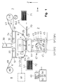
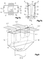
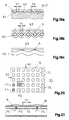
- Fig. 1 shows a flat embossing machine according to the invention for a embossing flat material 5, with a flat-flat press 2, with an embossing table 3 and as a counterpart a tool plate 4 with clichés 23 and with at least one embossing foil web 6.
- the flat material 5 to be embossed consists in this example of sheet 5.1, which from an investor 71 a register device 70 led to the flat embossing table 3, there at a standstill stamped and then stacked in a boom 72.
- Press is a toggle press 41 with four toggle lever pairs 43, with joints 44 and 45 and two pairs of tie rods 42.
- the tool plate 4 is adjustable in the Z direction by means of a positioning device 61, e.g.
- the embossing material is on one or more film webs 6, 6.1, 6.2 of unwinding rolls 7, 7.1, 7.2 via a first film loop store upstream of the press 10 and a film feed device 24 on one Side of the embossing table 3 and a clamping device 25 on the other side of the embossing table and then a film discharge device 8 fed.
- the film web 6 can be connected to the press via a second one Foil loop storage 20 on one or more winding rolls 80 are performed.
- Foil removal device 81 e.g. in the form of a compacting or shredding system, be used.
- the film feed device 24 is a precisely controllable slip-free feed of the film web 6, e.g. by means of lighter Rollers or suction elements, ensured while the tensioning device 25 an adjustable, optimal, even film tension on the embossing table generated, so that the film at the embossing location, smooth and without distortion and stretching for embossing is held at a standstill.
- the film feed device 24 is connected downstream of the press and the Tensioning device 25, e.g. as a precisely adjustable slip brake with constant Braking force or film tension, upstream of the press. It is the other way round also possible with a downstream tensioning device 25 a uniform Train to exert on the film web, which from an upstream Foil feed device is controlled precisely and without slippage (e.g. in Fig. 14).
- the flat embossing printing machine has a film feed and storage control 52 with an associated operating and display device 40.
- This feed control VV (t) must be carried out as gently, precisely and quickly as possible, so that the film web 6 is held precisely on the embossing table 3 during the printing phase TP (see FIG. 4) and then quickly and nevertheless gently into the during the unpressurized phase TL the next embossing position is brought forward.
- large, rapidly changing speed differences result between the relatively constant unwinding or winding speeds V7, V8 on the one hand and the intermittent feed speed VV (t).
- the accumulators are connected to a differential pressure device 30, which exerts an air pressure difference on the loops 12 in the accumulator and thus always keeps these loops smooth and stretched.
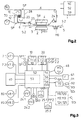
- FIG. 2 shows a flat embossing printing machine with a Endless web 5.2 as flat material 5 to be embossed with a dancer roller store 110, here the flat material and the film web 6 in the opposite direction are promoted, while Fig. 1 the advantageous in many cases Synchronization of flat material 5 and film web 6 illustrated.
- the film side Speed ratios with respect to VV, V7, V8 remain the same here same as described for Figure 1.
- the two film loop stores 10 and 20 are designed as a double labyrinth memory 28 with a common one internal suction as a differential pressure device 30. This represents a particularly simple and compact design of a double storage Measurement and monitoring of the loop depth LT and thus also the loop length L in the memories are film loop sensors SF (see FIG. 6).
- FIG. 3 shows a circuit diagram with a machine control 50, a film web and storage control 52, and a control of the toggle lever geometry 54, a print control 56 and a register control 58 for sheet or for endless track machines 59, as well as with assigned sensors SF, SB, SP and SD and with an operating and display device 40 for those concerned Adjustment and control functions.
- the example illustrates the controls of one Machine with two independently controllable film webs 6.1, 6.2 with Unwinding rolls 7.1, 7.2 or winding rolls 80.1, 80.2 and associated sensors to determine the unwinding speed V7.1, V7.2 or the winding speed V8.1, V8.2 (e.g. determined from roller diameter and speed).
- the corresponding are also on the film feed devices 24.1, 24.2 Feed speeds VV1, VV2 determined (e.g. by means of Encoder on servo motors).
- VV1, VV2 Feed speeds
- the film tensioning devices 25.1, 25.2 optimal film tension forces FF1, FF2 directly or indirectly adjustable and controllable.
- These film clamping forces FF1, FF2 are on the film web in question and the chosen embossing process can be tuned to match the embossing foils on the one hand, as gently as possible and without overstretching, and on the other hand, nevertheless, a precise, stretched alignment and positioning the foils are reached at the embossing location 3, this and during the embossing process is optimally adjustable.
- An additional film-like alignment of the film webs 6 on the Clichés 23 of the tool plate 4 can be made using film image sensors SB1, SB2 take place (see Fig. 2 and 15a). This is e.g. required for embossing Holograms or foil images, which register to the clichés position (and from the other side the flat material is also the register device positioned with respect to the clichés).
- the foil and Memory controller 52 will also loop the two Stores 10 and 20 controlled and monitored, e.g. through film web sensors SF1.1, SF1.2 in memory 10 and sensors SF2.1, SF2.2 in memory 20, which each capture the loop depths LT1.1, LT1.2 and LT2.1, LT2.2.
- this film web and storage controller 52 can also control the toggle lever geometry as additional functions 54, e.g. by adjusting the distance XS between the toggle joint points and thus influencing the embossing time DT, and a control 56 of the Pressure force via the positioning device 61 of the press with the aid of pressure force sensors SP1 to SP4 (Fig. 1). Also a register control 58 for sheet machines with SDi sensors and actuators 91, 92, 93 (according to FIG. 1, 19) or a register control 59 for endless web machines with web memories 110, 120, web edge controls 112, 113 and web feed and Web tensioning devices 124, 125 result in an advantageous combination.
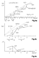
- FIG. 4 illustrates the feed control using an example with a five-cycle period VV, the film feed S (t) and the loop formation L (t) in the memories as a function of time over several embossing cycles. This is done here a relatively small film feed over four cycles (e.g. each 7 cm) and then a large feed in the fifth cycle (e.g. by 77 cm).
- FIG. 4b shows this course over the cycles 4, 5 and 1 in more detail.
- the feed S (t) is controlled as evenly as possible, without large changes in speed, ie with the lowest possible accelerations (d2S / dt 2 ). This is particularly important in the fifth cycle, when large changes in the loop length (from L2 to L1) occur in a short time during the depressurized phase TL of the cycle.
- the feed S (t) 0 must be during the printing phase TP and in particular during the embossing time DT, that is to say the film web must rest exactly on the embossing table.
- the line S7.2 (t) shows here, by way of example, a different time profile for a second film web 6.2, which here has a higher unwinding speed V7.2.
- FIG. 4c shows the change over time in the loop length L (t) in Foil loop memory 10 according to the feed movement S (t) according to Fig. 4b.
- FIG. 4d shows an enlarged feed S (t) in cycle 5 and the influence of the adjustment of the embossing time DT and thus also the pressure phase TP by a toggle lever adjustment according to FIGS. 16-18.
- a short embossing time DT1 a small value of TP1 results and remains accordingly a larger area TL1 for changing the feed speed VV and for changing the loop length L in the memories.
- the cycle time T0 and accordingly also the phases TP and TL become very small, which requires correspondingly higher feed speeds during the unpressurized phase TL.
- the film loop 12 runs along the guide walls 16, 17 and parallel to these.
- the guide walls 16, 17 can e.g. also tapered the arrangement of guide walls (as well as any Side walls) and differential pressure devices so coordinated is that a uniform air flow for optimal training of the desired film loop in the entire area between minimum loop length L1 and maximum loop length L2 are created.
- the determination and The loop length L is monitored here with a distance sensor SF (e.g. as an optical or ultrasonic detector), which is at the memory input is arranged and measures the loop depth LT. Then from LT Loop length L can be calculated.
- a distance sensor SF e.g. as an optical or ultrasonic detector
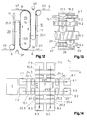
- FIGS. 7a, b show a film loop memory with side walls 18, 19 from above and from the side.
- the example shows another variant of a adjustable memory geometry, with which, matched to the differential pressure device, an optimal local flow distribution for a perfect Loop formation, e.g. also of different widths of film, can be adjusted.
- With sliding side walls 18, 19 or lids 22 attached thereto may have adjustable openings or slots 13 are formed.
- the film loop memory according to FIG. 8 has one as another example Suction box 15 with an inlet opening 14 for the film webs 6.1, 6.2 and with a suction fan 32 at the loop end or at the lower end of the Suction box.
- the loop memory can simultaneously several film webs 6.1, 6.2 (different types and Width), which are independently promoted and thus form different loops. To achieve optimal flow conditions for each loop you can use the variable covers 26 approximately the same size free inlet openings on both sides of each film web 6.1, 6.2 27 can be set.
- the differential pressure devices can the film loop storage also suction rolls 34 or suction wall elements 35 with circumferential perforated bands 36, which are advantageous additionally combined with a pressure or suction fan 31, 32.
- FIG. 10 shows a suction roller 34 with a suction area 37 on the input side Promotion of the film web 6 into the memory.
- the loop formation is supported here by a pressure blower 31.
- a perforated suction wall element 35 conveys a rotating one Perforated tape 36 via the suction and conveying area 37 to the film web 6 Forming a loop in the memory.
- This memory is suitable e.g. particularly good for long loops with very narrow foil webs.
- FIG. 12 shows a suction wall element 35 with perforated band 36, the one running downwards Area 35.1 forms a transport wall of a feed store 10 and whose upward area 35.2 is a transport wall for a discharge store 20 forms.
- Figure 13 shows a double memory 29, which has two compartments 16.1, 17.1 and 16.2, 17.2, these two compartments having a plurality of film webs 6.1 to 6.4 alternately and each spaced apart among the subjects exhibit. Both compartments can be combined with only one differential pressure device operate.
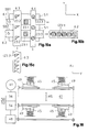
- Figure 14 illustrates an example of a machine with multiple longitudinal and Transversal film webs (in the X and Y directions), which can be controlled independently are.
- Two longitudinal tracks 6.1 and 6.2 with feed speeds VV1, VV2 have separate feed devices 24.1, 24.2 and clamping devices 25.1, 25.2 and shared film loop storage 10.1, 20.1.
- Two Cross tracks 6.3, 6.4 with feed speeds VV3, VV4 have separate Feed devices 24.3, 24.4 and clamping devices 25.3, 25.4 and common film storage 10.2 and 20.2.
- FIG. 15 illustrates an embossing work with several different embossing foil webs with different embossed goods and different clichés, which is carried out simultaneously in one stamping process.
- the film webs in the longitudinal and transverse directions can be simultaneously with more clichés and more complex images.
- Condition is that no clichés are arranged in the crossing areas of the film webs are.
- a sheet 5.1 in to be embossed is shown in FIG. 15a Y direction divided into two identical areas.
- In the X direction with two identical film webs 6.1, 6.2 with image units corresponding to the Clichés 23.1 coined.
- FIG. 15b shows the pronounced image film web 6.2 and FIG. 15c the distinctive color film web 6.3 with a 3-cycle period.
- the order the film webs and their individual feed control is done in such a way that the foil stamping is used in the best possible way.
- a flat embossing printing machine is created, which is very demanding and complex embossing tasks in one pass at high speed and can perform in the best quality and also the film webs little burdened and whose embossed goods can be used in the best possible way.
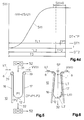
- Figures 16-18 illustrate the combination of the inventive Machine with a geometry adjustment or an embossing time adjustment (DT).
- DT embossing time adjustment
- Figure 16 shows a geometry adjustment of a toggle press with seen from above four pairs of toggle levers, their lower four toggle lever joints 45 (see Figure 1) are adjusted simultaneously by a servo drive 48 via a Transmission to the four joints 45. The adjustment takes place e.g.
- each over one Spindle and an adjusting wedge 49 so that the distance XS of the joints 45 is adjustable by means of the controllable motors 48 and a geometry control 54.
- controllable motors 48 and a geometry control 54 there are also other forms of drive (e.g. hydraulic or with Manual drive) possible or all four joints 45 can be directly with one synchronously controlled motor can be moved.
- the adjustment can be programmable and is preferably done step by step only during the depressurized phase (TL).
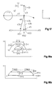
- FIG. 17 illustrates the geometry adjustment on one of the toggle lever pairs 43, which are moved by the tie rods 42.
- the setting XS1 ⁇ 0 results in a maximum deflection position 43a, the toggle levers 43, 43a not fully reaching their elongated position 46.
- the setting XS2 0, the elongated length 46 is just reached in the maximum deflection position 43b.
- the setting XS3>0 the stretched length 46 is exceeded up to the maximum deflection 43c. This results in
- the height difference DH results from the extent to which a given flat material 5 to be embossed can be compressed. This also results in the course of the press pressure force F (t) corresponding to the stroke movement H (t). If in case a) the stretched position 46 is not completely reached, the tool plate 4 must be adjusted accordingly in the direction Z4 by means of the positioning device 61 in order to compensate for the missing height H.
- the embossing printing machine has sensors SP1 to SP4 for measuring the press pressure forces F (see FIGS. 1 and 16).
- the pressure control 56 controls the tool plate 4 in the direction Z4 by means of the positioning device 61, so that a desired predetermined working pressure F can be kept constant automatically.
- the pressure control can also contain various functions for controlling the pressure force.
- optimal parameter values can be set both with regard to the embossing time DT and with respect to the embossing pressure force F, and the highest embossing quality and machine performance can thus be achieved.
- This control of the toggle lever geometry and the printing phase can also be used to optimize the embossing quality independently of the loop stores according to the invention.
- films of various types and Widths can be processed optimally.
- very wide and very thin Foils with a thickness of e.g. 15 - 30 ⁇ are extremely difficult to work properly to transport.
- the insulating plastic carrier material of the foils is electrostatically charged, what on the guide walls (inlet walls 16 and Outlet walls 17) of the accumulator may have relatively high frictional forces can result, which lead to distortion and hull formation of the film webs can.
- An important development of the invention is the frictional forces of the foil webs running over it, especially on the inlet walls 16 to keep the loop storage small or to reduce it to one size, that the loop formation and the transport can take place optimally.
- FIGS. 19 to 23 Various Measures and means for this are shown in FIGS. 19 to 23 shown.
- the Ratio of contacted to covered area F1 / F0 is less than 50% and is preferably even less, e.g. 10 - 30%.
- Such structured surfaces 63 can be formed in various ways e.g. through grooves or channels 64, according to FIGS. 19 a and 20, or by means of grids or fine-mesh wire meshes 65 according to FIG. 91b or by perforated sheets, knobbed sheets or corrugated sheet 66 according to FIG. 19c.
- the lattice constant or the structural distances of these structured surfaces are preferably only 1mm or less, e.g. 0.3 - 1 mm.
- FIG. 20 shows a top view of an example of a structured surface with Longitudinal and transverse channels 64, here an area ratio F1 / F0 of approx. 25% is illustrated.
- FIG. 21 Another particularly simple and effective method for reducing the Contact area portion F1 or the frictional force of the film web on the inlet wall 16 consists of the film web by partially blowing in air partially detachable from the inlet wall.
- the Inlet wall 16 has injection holes 75 through which an overpressure chamber 74 local air is blown in under the film.
- This air-assisted Reduction of friction on the inlet wall is the one to be transported Corresponding foils, easy to dose by controlling the Overpressure P3 in the chambers 74. This can e.g. 2 - 4 bar.
- the Blow-off openings 75 are preferably dimensioned relatively small and large Spaced from each other. The diameter of the blow-off openings is e.g.
- the guide walls are metallically conductive and the ventilated inlet walls can be a smooth surface (Fig. 21) or a textured Surface (Fig.20).
- FIG. 22 shows a further variant for reducing the frictional force Applying a potential U2 to the inlet wall 16 with an adjustable one Voltage source 96.
- the inlet wall is metallically conductive and from the environment trained in isolation.
- the potential difference U1 - U2 between the film web 6 and the guide wall 16 reduced so far that the desired low value of the friction force is reached.
- the setting of the Potential U2 on the inlet wall 16 is such that an optimal smooth Loop formation and film guidance is achieved.
- the potential U1 of the film web 6 is determined by means of a capacitive potential probe 95 and then the potential U2 is set or regulated.
- FIG. 23 shows an example with a double compartment memory 29 before and after the embossing press and each with a film web 6.1, 6.2 in a respective compartment two double compartments.
- the loops are formed in the store by vacuum suction using a common suction fan 32.
- the four inlet walls 16.1, 16.2 have ventilation with overpressure chambers 74 with a pressure P3 and injection openings 75.
- the four outlet walls 17.1, 17.2 are, however, expressly not ventilated. The friction force the outlet walls are therefore deliberately higher than on the inlet walls, so that the film web is slightly stretched for perfect further transport becomes.
- a drag wheel 53 with a rotary encoder detects speed and Feed of the running film web, with which the motor of the winding roll 80 as well as feed and loop formation in the stores can be controlled.
- FIG. 24 shows the combination of the flat embossing printing machine according to the invention with a register control 58 of the flat material. That combination enables both-sided optimization on the film web side with regard to the Foil guidance and alignment as well as regarding the flat material guidance for precise image alignment.
- On the film side e.g. Film subjects like holograms or film images by means of the film image sensors SB (FIG. 15a, FIG. 2) precisely aligned with the clichés 23 on the tool plate 4, while the sheet 5.1 by the register control also in exact position the location of the clichés are aligned.
- Such register control for Sheet-fed machines are known from EP-A-708 046.
- the register feeding device 70 for flat embossing printing machines has leading edge stops, a side stop and position sensors SD1, SD2, SD3 for detecting print marks M1, M2, M3 of sheet 5.1 and two the detectors SD4, SD5 assigned to the front stops A1, A2 for Detect the leading edge of the sheet.
- the front stops are A1, A2 adjustable by actuators 91, 92 until the front print marks M1, M2 of the sheet are detected by the corresponding sensors SD1, SD2 are.
- An actuator 93 then adjusts the side stop or sideshift A3 until the page print mark M3 from the assigned position sensor SD3 is recorded.
- a register controller 58 controls this register correction with the position sensors SD1, SD2, SD3, the detectors SD4, SD5 and the actuators 91, 92, 93. This simply results in a reliable automatic register correction for each individual sheet and increased thus, in combination with the film guidance and control, the print quality.
- FIG. 25 shows, seen from above, a register control 59 for Endless web machines (Fig. 2) with sensors SD1, SD3 for detecting Print marks M1, M3.
- the endless web 5.2 runs from an unwind roll 107 to a take-up reel 108 with web edge controls 112, 113, web stores 110, 120 (designed as dancer rollers or also as a suction accumulator), a web tensioning device 125 and a web feed device 124
- the continuous web is aligned in the transverse direction Y with the print mark M3 through the known web edge controls 112, 113 and Alignment with the mark M1 in the longitudinal direction X is carried out with the web feed device 124 controlled.
- Foil web control also here web storage 110 and 120 for the endless web 5.2 used.
Abstract
Description
Die Erfindung betrifft eine Flach-Prägedruckmaschine für ein zu beprägendes
Flachmaterial mit einer Flach-Presse, Prägetisch und Werkzeugplatte gemäss
Oberbegriff von Anspruch 1. Bei derartigen Maschinen, mit denen Prägedruckaufgaben
besonders anspruchsvoller Qualität ausführbar sind, müssen
die Prägefolienbahnen während der Prägedruckphase auf dem Prägetisch
genau positioniert stillgehalten werden und anschliessend während der drucklosen
Phase rasch in die nächste Prägeposition der Folienbahn vorgeschoben
werden. Dabei müssen die empfindlichen Prägefolienbahnen schonend behandelt
und gefördert werden. Dies ist schwierig zu erreichen, denn bedingt durch
diesen Prägezyklus ergibt sich ein sehr ungleichmässiger Vorschub am Prägeort,
während die trägen Abwickelrollen im wesentlichen gleichförmig angetrieben
werden. Die daraus entstehenden Längenänderungen der Folienbahn
wurden bisher durch Tänzerwalzen kompensiert. Dies war möglich bis zu
mittleren Prägegeschwindigkeiten, wobei allerdings die Folienbahngeschwindigkeiten,
die Anzahl der gleichzeitig verarbeitbaren Folienbahnen und vor
allem auch die Maschinengeschwindigkeit begrenzt werden. Anderseits ermöglicht
jedoch die Flach-Flach-Prägegeometrie höchste Prägequalitäten, vor
allem auch für Reliefdruck und für grosse Bildformate. Eine Verbesserung in
Teilbereichen konnte z.B. mit einer Registersteuerung nach EP-A-708 046
oder mit einer automatischen Drucksteuerung nach EP-A-749 001 erreicht
werden. Die grundsätzlichen Beschränkungen blieben jedoch bestehen. The invention relates to a flat embossing printing machine for a to be embossed
Flat material with a flat press, embossing table and tool plate according to
Preamble of
Es ist daher Aufgabe der vorliegenden Enfindung, eine Flach-Prägedruckmaschine zu schaffen, welche beste Prägequalität auch bei sehr hohen Maschinengeschwindigkeiten ermöglicht und welche für einen erweiterten Bereich möglicher Prägeaufgaben mit vielen Folienbahnen und komplexen Bildern einsetzbar ist. Dazu muss vor allem auch eine schonende und rasche Förderung mehrerer ganz unterschiedlicher Folienbahnen möglich sein.It is therefore an object of the present invention, a flat embossing printing machine to create the best embossing quality even at very high machine speeds enables and which for an extended area possible embossing tasks with many foil webs and complex images can be used. Above all, this requires careful and rapid funding several completely different film webs may be possible.
Diese Aufgabe wird erfindungsgemäss gelöst durch eine Flach-Prägedruckmaschine
nach Anspruch 1. Durch die Folienschlaufenspeicher mit einer Differenzdruckvorrichtung
werden zum Längenausgleich Schlaufen der Folienbahn
rasch, schonend und auf kompaktem Raum gebildet, während gleichzeitig die
Folienvorschubeinrichtung mit der zugeordneten Vorschub- und Schlaufenspeichersteuerung
eine optimale Positionierung am Prägeort sicherstellt. Die
abhängigen Ansprüche betreffen vorteilhafte Weiterbildungen der Erfindung.
Sie betreffen weitere Verbesserungen der Präge-Maschinenfunktionen und -
eigenschaften und ermöglichen einen noch breiteren Einsatzbereich. Besonders
vorteilhafte Kombinationen ergeben die zusätzliche Verstellung von
Kniehebelgeometrie und Prägezeit sowie Drucksteuerung der Presse und
Registersteuerung des zu beprägenden Flachmaterials.According to the invention, this object is achieved by a flat embossing printing machine
according to
Im folgenden wird die Erfindung anhand von Beispielen und Figuren weiter erläutert. Es zeigen:
- Fig. 1
- eine erfindungsgemässe Flach-Prägedruckmaschine mit Folienbahnspeichern und Vorschubsteuerung
- Fig. 2
- ein weiteres Beispiel mit Doppelspeichern und Endlosbahn
- Fig. 3
- ein Schaltschema mit Folienbahn- und Speichersteuerung sowie mit weiteren Funktionen
- Fig. 4
- den zeitlichen Verlauf von Folienvorschub S und Schlaufenbildung L im Speicher
- Fig. 5, 6
- Beispiele von Folienschlaufenspeichern mit Führungswänden und Differenzdruckvorrichtungen
- Fig. 7
- einen Folienspeicher mit einstellbaren Seitenwänden
- Fig. 8, 9
- Saugkastenspeicher mit variablen Abdeckungen
- Fig. 10
- einen Speicher mit Saugwalze
- Fig. 11
- einen Speicher mit Saugwandelement und Lochband
- Fig. 12
- einen Doppelspeicher mit Saugwandelement
- Fig. 13
- einen Doppelspeicher mit mehreren Folienbahnen
- Fig. 14
- eine Maschine mit mehreren unabhängigen Längs- und Querfolienbahnen
- Fig. 15
- ein Prägebeispiel mit mehreren Prägefolienbahnen und Clichés
- Fig. 16
- eine Geometrieverstellung von Gelenken einer Kniehebelpresse
- Fig. 17
- schematisch eine Geometrieverstellung von Kniehebeln
- Fig. 18
- Hubbewegungsverläufe H des Prägetischs in Funktion der Zeit
- Fig. 19 a,b,c
- Beispiele von strukturierten Führungsflächen
- Fig. 20
- eine strukturierte Einlaufwand mit Einblasöffnungen
- Fig. 21
- eine belüftete Einlaufwand
- Fig. 22
- eine Einlaufwand mit angelegtem Potential
- Fig. 23
- Doppelfachspeicher mit belüfteten Einlaufwänden
- Fig. 24
- eine Registereinzugsvorrichtung in einer Bogenmaschine
- Fig. 25
- eine Endlosbahnmaschine mit Registersteuerung
- Fig. 1
- a flat embossing printing machine according to the invention with film web storage and feed control
- Fig. 2
- another example with double storage and endless track
- Fig. 3
- a circuit diagram with film web and memory control as well as with other functions
- Fig. 4
- the time course of foil feed S and loop formation L in the memory
- 5, 6
- Examples of film loop stores with guide walls and differential pressure devices
- Fig. 7
- a film storage with adjustable side walls
- 8, 9
- Suction box storage with variable covers
- Fig. 10
- a memory with suction roller
- Fig. 11
- a memory with suction wall element and perforated tape
- Fig. 12
- a double storage with suction wall element
- Fig. 13
- a double storage with several foil webs
- Fig. 14
- a machine with several independent longitudinal and transverse film webs
- Fig. 15
- an embossing example with several embossing foils and clichés
- Fig. 16
- a geometry adjustment of joints of a toggle press
- Fig. 17
- schematically a geometry adjustment of toggle levers
- Fig. 18
- Stroke movements H of the embossing table as a function of time
- 19 a, b, c
- Examples of structured guide surfaces
- Fig. 20
- a structured inlet wall with injection openings
- Fig. 21
- a ventilated inlet wall
- Fig. 22
- an inlet wall with applied potential
- Fig. 23
- Double compartment storage with ventilated inlet walls
- Fig. 24
- a register feeder in a sheet machine
- Fig. 25
- an endless web machine with register control
Fig. 1 zeigt eine erfindungsgemässe Flach-Prägedruckmaschine für ein zu
beprägendes Flachmaterial 5, mit einer Flach-Flach-Presse 2, mit einem Prägetisch
3 und als Gegenstück eine Werkzeugplatte 4 mit Clichés 23 sowie mit
mindestens einer Prägefolienbahn 6. Das zu beprägende Flachmaterial 5
besteht in diesem Beispiel aus Bogen 5.1, welche von einem Anleger 71 über
eine Registervorrichtung 70 zum flachen Prägetisch 3 geführt, dort im Stillstand
beprägt und anschliessend in einem Ausleger 72 gestapelt werden. Als
Presse dient eine Kniehebelpresse 41 mit vier Kniehebelpaaren 43, mit Gelenken
44 und 45 und zwei Paaren von Zugstangen 42. Die Werkzeugplatte 4 ist
in Z-Richtung einstellbar mittels einer Positioniervorrichtung 61, z.B. mit
einer motorgetriebenen Spindel, welche einen Schiebekeil verstellt. Das Prägematerial
wird auf einer oder mehreren Folienbahnen 6, 6.1, 6.2 von Abwickelrollen
7, 7.1, 7.2 über einen ersten, der Presse vorgeschalteten Folienschlaufenspeicher
10 und eine Folienvorschubeinrichtung 24 auf der einen
Seite des Prägetischs 3 sowie eine Spanneinrichtung 25 auf der andern Seite
des Prägetischs gefördert und anschliessend einer Folienabführeinrichtung 8
zugeführt. Dabei kann die Folienbahn 6 über einen zweiten, der Presse nachgeschalteten
Folienschlaufenspeicher 20 auf eine bzw. mehrere Aufwickelrollen
80 geführt werden. Anstelle von Aufwickelrollen 80 kann auch eine direkte
Folienabführeirrichtung 81, z.B. in Form einer Kompaktier- oder Schredderanlage,
eingesetzt sein. Mit der Folienvorschubeinrichtung 24 wird ein
genau steuerbarer schlupffreier Vorschub der Folienbahn 6, z.B. mittels leichter
Walzen oder Saugelementen, sichergestellt, während die Spanneinrichtung
25 am Prägetisch eine einstellbare optimale, gleichmässige Folienspannung
erzeugt, so dass die Folie am Prägeort positionsgenau, glatt und ohne Verzug
und Überdehnung zum Prägen im Stillstand gehalten wird. Mit Vorteil ist
dabei die Folienvorschubeinrichtung 24 der Presse nachgeschaltet und die
Spanneinrichtung 25, z.B. als genau einstellbare Schlupfbremse mit konstanter
Bremskraft bzw. Folienspannung, der Presse vorgeschaltet. Umgekehrt ist es
auch möglich, mit einer nachgeschalteten Spanneinrichtung 25 einen gleichmässigen
Zug auf die Folienbahn auszuüben, welche von einer vorgeschalteten
Folienvorschubeinrichtung genau und schlupffrei ablaufend gesteuert wird
(z.B. in Fig. 14).Fig. 1 shows a flat embossing machine according to the invention for a
embossing
Die Flach-Prägedruckmaschine weist eine Folienvorschub- und Speichersteuerung
52 mit zugeordnetem Bedienungs- und Anzeigegerät 40 auf. Damit wird
der Folienvorschub am Prägeort dem Flachpressen Zyklus entsprechend gesteuert,
wobei die Folienbahn während der Druckphase TP auf dem Prägetisch
3 stillgehalten wird und während der drucklosen Phase TL in die nächste
Prägeposition vorgezogen wird, mit Zyklendauer
Zusätzlich zur Maschinensteuerung 50 mit Folien- und Speichersteuerung 52 können weitere vorteilhafte Kombinationen für Steuerfunktionen integriert werden (siehe Fig. 3):
- eine Steuerung der Kniehebelgeometrie 54 und eine Pressen-
Drucksteuerung 56, wie dies inden Figuren 16bis 18 weiter erläutert wird, - sowie eine Registersteuerung 58 für Bogen gemäss Fig. 24, bzw.
eine Registersteuerung 59 für Endlosbahnen gemäss Fig. 25.
- a control of the
toggle lever geometry 54 and apress pressure control 56, as is further explained in FIGS. 16 to 18, - as well as a
register control 58 for sheets according to FIG. 24, or aregister control 59 for endless webs according to FIG. 25.
Figur 2 zeigt als weiteres Beispiel eine Flach-Prägedruckmaschine mit einer
Endlosbahn 5.2 als zu beprägendes Flachmaterial 5 mit einem Tänzerwalzenspeicher
110, wobei hier das Flachmaterial und die Folienbahn 6 im Gegenlauf
gefördert werden, während Fig. 1 den in vielen Fällen vorteilhaften
Gleichlauf von Flachmaterial 5 und Folienbahn 6 illustriert. Die folienseitigen
Geschwindigkeitsverhältnisse bezüglich VV, V7, V8 bleiben auch hier die
gleichen wie zu Figur 1 beschrieben ist. Die beiden Folienschlaufenspeicher
10 und 20 sind als Doppellabyrinthspeicher 28 ausgebildet mit einer gemeinsamen
inneren Absaugung als Differenzdruckvorrichtung 30. Dies stellt eine
besonders einfache und kompakte Bauweise eines Doppelspeichers dar. Zur
Messung und Überwachung der Schlaufentiefe LT und damit auch der Schlaufenlänge
L in den Speichern dienen Folienschlaufensensoren SF (s. Fig. 6).As a further example, FIG. 2 shows a flat embossing printing machine with a
Endless web 5.2 as
Figur 3 zeigt ein Schaltschema mit einer Maschinensteuerung 50, einer Folienbahn- und Speichersteuerung 52, einer Steuerung der Kniehebelgeometrie
54, einer Drucksteuerung 56 und einer Registersteuerung 58 für Bogen- bzw.
für Endlosbahn-Maschinen 59, sowie mit zugeordneten Sensoren SF, SB, SP
und SD und mit einem Bedienungs- und Anzeigegerät 40 für die betreffenden
Einstell- und Steuerfunktionen. Das Beispiel illustriert die Steuerungen einer
Maschine mit zwei unabhängig steuerbaren Folienbahnen 6.1, 6.2 mit
Abwickelrollen 7.1, 7.2 bzw. Aufwickelrollen 80.1, 80.2 sowie zugehörigen Sensoren
zur Bestimmung der Abwickelgeschwindigkeit V7.1, V7.2 bzw. der Aufwickelgeschwindigkeit
V8.1, V8.2 (z.B. ermittelt aus Rollendurchmesser und Drehzahl).
An den Folienvorschubeinrichtungen 24.1, 24.2 werden auch die entsprechenden
Vorschubgeschwindigkeiten VV1, VV2 bestimmt (z.B. mittels
Encoder an Servomotoren). Mit den Folienspanneinrichtungen 25.1, 25.2 sind
optimale Folienspannkräfte FF1, FF2 direkt oder indirekt einstellbar und
steuerbar. Diese Folienspannkräfte FF1, FF2 sind so auf die betreffende Folienbahn
und den gewählten Prägevorgang abstimmbar, dass die Prägefolien
einerseits möglichst schonend und ohne Überdehnung gefördert werden und
anderseits dennoch eine genaue, gestreckte Ausrichtung und Positionierung
der Folien am Prägeort 3 erreicht wird wobei dies und während dem Prägevorgang
optimal einstellbar ist.FIG. 3 shows a circuit diagram with a
Eine zusätzliche folienbildmässige Ausrichtung der Folienbahnen 6 auf die
Clichés 23 der Werkzeugplatte 4 kann mittels Folienbildsensoren SB1, SB2
erfolgen (siehe Fig. 2 und 15a). Dies ist z.B. erforderlich zum Prägen von
Hologrammen oder Folienbildern, welche registergenau auf die Clichés zu
positionieren sind (und von der anderen Seite her wird das Flachmaterial mit
der Registervorrichtung bezüglich der Clichés positioniert). Mit der Folien- und
Speichersteuerung 52 werden auch die Schlaufenbildungen in den beiden
Speichern 10 und 20 gesteuert und überwacht, z.B. durch Folienbahnsensoren
SF1.1, SF1.2 im Speicher 10 und die Sensoren SF2.1, SF2.2 im Speicher 20,
welche je die Schlaufentiefen LT1.1, LT1.2 und LT2.1, LT2.2 erfassen. Als
vorteilhafte Kombinationen mit dieser Folienbahn- und Speichersteuerung 52
können auch als weitere Funktionen eine Steuerung der Kniehebelgeometrie
54, z.B. durch Verstellung des Abstandes XS der Kniehebelgelenkpunkte und
damit Beeinflussung der Prägezeit DT, erfolgen sowie eine Steuerung 56 der
Druckkraft über die Positioniervorrichtung 61 der Presse mit Hilfe von Druckkraftsensoren
SP1 bis SP4 (Fig. 1). Auch eine Registersteuerung 58 für Bogenmaschinen
mit Sensoren SDi und Stellgliedern 91, 92, 93 (nach Figur 1,
19) oder eine Registersteuerung 59 für Endlosbahnmaschinen mit Bahnspeichern
110, 120, Bahnkantensteuerungen 112, 113 und Bahnvorschub- und
Bahnspanneinrichtungen 124, 125 ergibt eine vorteilhafte Kombination.An additional film-like alignment of the
Figur 4 illustriert an einem Beispiel mit einer Fünf-Zyklen-Periode die Vorschubsteuerung VV, den Folienvorschub S(t) und die Schlaufenbildung L(t) in den Speichern in Funktion der Zeit über mehrere Prägezyklen. Dabei erfolgt hier über vier Zyklen ein relativ kleiner Folienvorschub (von z.B. je 7 cm) und anschliessend ein grosser Vorschub im fünften Zyklus (um z.B. 77 cm). FIG. 4 illustrates the feed control using an example with a five-cycle period VV, the film feed S (t) and the loop formation L (t) in the memories as a function of time over several embossing cycles. This is done here a relatively small film feed over four cycles (e.g. each 7 cm) and then a large feed in the fifth cycle (e.g. by 77 cm).
Figur 4a zeigt den Verlauf der Bandförderung S7(t) mit einer Bahngeschwindigkeit
Figur 4b zeigt diesen Verlauf über die Zyklen 4, 5 und 1 genauer. Der Vorschub
S(t) wird dabei möglichst ausgeglichen gesteuert, ohne grosse
Geschwindigkeitsänderungen, d.h. mit möglichst geringen Beschleunigungen
(d2S/dt2). Dies ist wichtig vor allem im fünften Zyklus, wenn in kurzer Zeit
grosse Änderungen der Schlaufenlänge (von L2 auf L1) auftreten während der
drucklosen Phase TL des Zyklus. Wie ersichtlich ist, muss während der
Druckphase TP und insbesondere während der Prägezeit DT der Vorschub
S(t) = 0 sein, d.h. die Folienbahn muss auf dem Prägetisch genau stillstehen.
Die Linie S7.2(t) zeigt hier beispielhaft auch einen anderen zeitlichen Verlauf
für eine zweite Folienbahn 6.2, welche hier eine höhere Abwickelgeschwindigkeit
V7.2 aufweist.Figure 4b shows this course over the
Figur 4c zeigt die zeitliche Veränderung der Schlaufenlänge L(t) im
Folienschlaufenspeicher 10 entsprechend der Vorschubbewegung S(t) gemäss
Fig. 4b.FIG. 4c shows the change over time in the loop length L (t) in
Figur 4d zeigt vergrössert den Vorschub S(t) im Zyklus 5 sowie den Einfluss
der Verstellung der Prägezeit DT und damit auch der Druckphase TP durch
eine Kniehebelverstellung gemäss Figuren 16 - 18. Bei einer kurzen Prägezeit
DT1 resultiert ein kleiner Wert von TP1 und entsprechend bleibt ein grösserer
Bereich TL1 für die Änderung der Vorschubgeschwindigkeit VV und für
die Änderung der Schlaufenlänge L in den Speichern. Bei grosser Prägezeit
DT2 und entsprechend grösserem Wert von TP2 resultiert entsprechend der
Beziehung
Figur 5 zeigt einen Folienschlaufenspeicher 10 mit zwei Führungswänden 16,
17, Umlenkrollen 39 und mit einem steuerbaren Druckgebläse 31 und/oder
einem Sauggebläse 32 als Differenzdruckvorrichtung. Diese erzeugen einen
Differenzdruck
Wie Figur 6 zeigt, können die Führungswände 16, 17 z.B. auch konisch verlaufen,
wobei die Anordnung von Führungswänden (sowie von allfälligen
Seitenwänden) und Differenzdruckvorrichtungen so aufeinander abgestimmt
wird, dass eine gleichmässige Luftströmung zur optimalen Ausbildung der
gewünschten Folienschlaufe im ganzen Bereich zwischen minimaler Schlaufenlänge
L1 und maximaler Schlaufenlänge L2 entsteht. Die Bestimmung und
Überwachung der Schlaufenlänge L erfolgt hier mit einem Distanzsensor SF
(z.B. als optischer oder Ultraschalldetektor), welcher am Speichereingang
angeordnet ist und die Schlaufentiefe LT misst. Aus LT kann dann die
Schlaufenlänge L berechnet werden.As Figure 6 shows, the
Die Figuren 7a, b zeigen einen Folienschlaufenspeicher mit Seitenwänden 18,
19 von oben und von der Seite. Das Beispiel zeigt eine weitere Variante einer
einstellbaren Speichergeometrie, mit welcher, abgestimmt auf die Differenzdruckvorrichtung,
eine optimale örtliche Strömungsverteilung für eine einwandfreie
Schlaufenbildung, z.B auch von unterschiedlich breiten Folienbahnen,
eingestellt werden kann. Mit verschiebbaren Seitenwänden 18, 19 oder
daran angebrachten Deckeln 22 können einstellbare Öffnungen oder Schlitze
13 gebildet werden. Diese Einstellungen von Geometrie und Öffnungen der
Speicher 10 können auch mittels Stellgliedern automatisch bzw. durch die
Steuerung 52 steuerbar ausgebildet werden.FIGS. 7a, b show a film loop memory with
Der Folienschlaufenspeicher nach Figur 8 weist als weiteres Beispiel einen
Saugkasten 15 auf mit einer Eingangsöffnung 14 für die Folienbahnen 6.1, 6.2
und mit einem Sauggebläse 32 am Schlaufenende bzw. am unteren Ende des
Saugkastens.The film loop memory according to FIG. 8 has one as another
Figur 9a, b zeigt von oben und von der Seite einen Saugkastenspeicher 15 mit
variablen Abdeckungen 26 an der Eingangsöffnung 14. Die Schlaufenspeicher
können gleichzeitig mehrere Folienbahnen 6.1, 6.2 (unterschiedlicher Art und
Breite) aufnehmen, welche unabhängig voneinander gefördert werden und
somit unterschiedliche Schlaufen ausbilden. Zur Erzielung optimaler Strömungsverhältnisse
für jede Schlaufe können mit den variablen Abdeckungen
26 beidseitig jeder Folienbahn 6.1, 6.2 etwa gleichgrosse freie Einlassöffnungen
27 eingestellt werden.9a, b show a
Wie in den Figuren 10 bis 12 illustriert wird, können die Differenzdruckvorrichtungen
der Folienschlaufenspeicher auch Saugwalzen 34 oder Saugwandelemente
35 mit umlaufenden Lochbändern 36 aufweisen, welche mit Vorteil
zusätzlich noch mit einem Druck- oder Sauggebläse 31, 32 kombiniert sind. As illustrated in Figures 10 through 12, the differential pressure devices can
the film loop storage also suction rolls 34 or
Figur 10 zeigt eingangsseitig eine Saugwalze 34 mit einem Saugbereich 37 zur
Förderung der Folienbahn 6 in den Speicher hinein. Die Schlaufenbildung
wird hier noch unterstützt durch ein Druckgebläse 31.FIG. 10 shows a
In Figur 11 fördert ein gelochtes Saugwandelement 35 mit einem umlaufenden
Lochband 36 über den Saug- und Förderbereich 37 die Folienbahn 6 zur
Ausbildung einer Schleife in den Speicher. Dieser Speicher eignet sich z.B.
besonders gut für lange Schlaufen mit sehr schmalen Folienbahnen.In FIG. 11, a perforated
Figur 12 zeigt ein Saugwandelement 35 mit Lochband 36, dessen abwärtslaufender
Bereich 35.1 eine Transportwand eines Zufuhrspeichers 10 bildet und
dessen aufwärtslaufender Bereich 35.2 eine Transportwand für einen Abfuhrspeicher
20 bildet.FIG. 12 shows a
Figur 13 zeigt einen Doppelspeicher 29, welcher zwei Fächer 16.1, 17.1 und
16.2, 17.2 aufweist, wobei diese beiden Fächer mehrere Folienbahnen 6.1 bis
6.4 abwechselnd und je mit Abstand untereinander auf die Fächer verteilt
aufweisen. Beide Fächer können zusammen mit nur einer Differenzdruckvorrichtung
betrieben werden.Figure 13 shows a
Figur 14 illustriert ein Beispiel einer Maschine mit mehreren Längs- und Querfolienbahnen (in X- und Y-Richtung), welche einzeln unabhängig steuerbar sind. Zwei Längsbahnen 6.1 und 6.2 mit Vorschubgeschwindigkeiten VV1, VV2 weisen separate Vorschubeinrichtungen 24.1, 24.2 und Spanneinrichtungen 25.1, 25.2 sowie gemeinsame Folienschlaufenspeicher 10.1, 20.1 auf. Zwei Querbahnen 6.3, 6.4 mit Vorschubgeschwindigkeiten VV3, VV4 weisen separate Vorschubeinrichtungen 24.3, 24.4 und Spanneinrichtungen 25.3, 25.4 sowie gemeinsame Folienspeicher 10.2 und 20.2 auf. Figure 14 illustrates an example of a machine with multiple longitudinal and Transversal film webs (in the X and Y directions), which can be controlled independently are. Two longitudinal tracks 6.1 and 6.2 with feed speeds VV1, VV2 have separate feed devices 24.1, 24.2 and clamping devices 25.1, 25.2 and shared film loop storage 10.1, 20.1. Two Cross tracks 6.3, 6.4 with feed speeds VV3, VV4 have separate Feed devices 24.3, 24.4 and clamping devices 25.3, 25.4 and common film storage 10.2 and 20.2.
Die Figur 15 illustriert eine Prägearbeit mit mehreren unterschiedlichen Prägefolienbahnen mit unterschiedlichem Prägegut und verschiedenen Clichés, welche gleichzeitig in einem Prägevorgang durchgeführt wird. Durch die Anordnung der Folienbahnen in Längs- und Querrichtung können gleichzeitig mit mehr Clichés und komplexere Bilder geprägt werden. Bedingung dabei ist, dass in den Kreuzungsbereichen der Folienbahnen keine Clichés angeordnet sind. Als einfaches Beispiel ist in Figur 15a ein zu beprägender Bogen 5.1 in Y-Richtung in zwei identische Bereiche unterteilt. In X-Richtung wird mit zwei identischen Folienbahnen 6.1, 6.2 mit Bildeinheiten entsprechend den Clichés 23.1 geprägt. Die Registerhaltigkeit dieser Folienbildeinheiten bezüglich der Clichés 23.1 und damit auch bezüglich des zu beprägenden Bogens 5.1 wird durch Folienbildsensoren SB1, SB2 (welche Folienbildmarken detektieren) überwacht und gesteuert. In Y-Richtung verlaufen zwei Folienbahnen 6.3, 6.4 mit unterschiedlichen Farbschichten als Prägegut und mit zugeordneten Clichés 23.2, 23.3.FIG. 15 illustrates an embossing work with several different embossing foil webs with different embossed goods and different clichés, which is carried out simultaneously in one stamping process. By the arrangement the film webs in the longitudinal and transverse directions can be simultaneously with more clichés and more complex images. Condition is that no clichés are arranged in the crossing areas of the film webs are. As a simple example, a sheet 5.1 in to be embossed is shown in FIG. 15a Y direction divided into two identical areas. In the X direction with two identical film webs 6.1, 6.2 with image units corresponding to the Clichés 23.1 coined. The registration of these film image units with regard to the Clichés 23.1 and thus also regarding the sheet to be embossed 5.1 is detected by film image sensors SB1, SB2 (which detect film image marks) monitored and controlled. Two film webs run in the Y direction 6.3, 6.4 with different layers of color as an embossed material and with assigned Clichés 23.2, 23.3.
In Figur 15b ist die ausgeprägte Bildfolienbahn 6.2 gezeigt und in Figur 15c die ausgeprägte Farbfolienbahn 6.3 mit einer 3-Zyklen Periode. Die Anordnung der Folienbahnen und deren individuelle Vorschubsteuerung erfolgt so, dass das Folienprägegut bestmöglich ausgenützt wird. Mit der erfindungsgemässen Kombination von kompakten, sehr rasch ansprechenden gemeinsamen Schlaufenspeichern für mehrere und unabhängig steuerbare Folienbahnen wird eine Flach-Prägedruckmaschine geschaffen, welche sehr anspruchsvolle und komplexe Prägeaufgaben in einem Durchgang mit hoher Geschwindigkeit und in bester Qualität ausführen kann und wobei zudem die Folienbahnen wenig belastet und deren Prägegut bestmöglich ausgenützt werden kann.FIG. 15b shows the pronounced image film web 6.2 and FIG. 15c the distinctive color film web 6.3 with a 3-cycle period. The order the film webs and their individual feed control is done in such a way that the foil stamping is used in the best possible way. With the inventive Combination of compact, very responsive common Loop storage for several and independently controllable film webs a flat embossing printing machine is created, which is very demanding and complex embossing tasks in one pass at high speed and can perform in the best quality and also the film webs little burdened and whose embossed goods can be used in the best possible way.
Die Figuren 16 - 18 illustrieren die Kombination der erfindungsgemässen
Maschine mit einer Geometrieverstellung bzw. einer Prägezeitverstellung
(DT). Damit ist eine Optimierung möglich in zwei Dimensionen, d.h. mittels
zweier unabhängiger Einstellgrössen: sowohl bezüglich des Folienvorschubs
S(t) als auch bezüglich des Prägeprozesses mit der Prägezeit DT. Dies ergibt
maximale Prägequalität und universelle Einsatzmöglichkeiten. Die Figur 16
zeigt von oben gesehen eine Geometrieverstellung einer Kniehebelpresse mit
vier Kniehebelpaaren, wobei deren untere vier Kniehebel-Gelenke 45 (siehe
Figur 1) gleichzeitig verstellt werden durch einen Servoantrieb 48 über eine
Transmission an die vier Gelenke 45. Die Verstellung erfolgt z.B. je über eine
Spindel und einen Verstellkeil 49, so dass der Abstand XS der Gelenke 45
einstellbar ist mittels der steuerbaren Motoren 48 und einer Geometrie-Steuerung
54. Es sind aber auch andere Antriebsformen (z.B. hydraulisch oder mit
Handantrieb) möglich oder es können alle vier Gelenke 45 direkt mit je einem
synchron gesteuerten Motor verschoben werden. Die Verstellung kann
programmierbar sein und erfolgt vorzugsweise schrittweise nur während der
drucklosen Phase (TL).Figures 16-18 illustrate the combination of the inventive
Machine with a geometry adjustment or an embossing time adjustment
(DT). This enables optimization in two dimensions, i.e. by means of
two independent setting parameters: both with regard to the film feed
S (t) as well as regarding the embossing process with the embossing time DT. This results in
maximum embossing quality and universal application possibilities. Figure 16
shows a geometry adjustment of a toggle press with seen from above
four pairs of toggle levers, their lower four toggle lever joints 45 (see
Figure 1) are adjusted simultaneously by a
Figur 17 illustriert die Geometrieverstellung an einem der Kniehebelpaare 43,
welche durch die Zugstangen 42 bewegt werden. Je nach Einstellung XS der
unteren Gelenke 45 resultieren unterschiedliche Verläufe der Hubmaxima
H(t) der Presse wie an drei Einstellungsbeispielen nachfolgend dargestellt
wird.
Mit der Einstellung XS1 < 0 resultiert eine maximale Auslenkungslage 43a,
wobei die Kniehebel 43, 43a ihre gestreckte Läge 46 nicht ganz erreichen.
Mit der Einstellung XS2 = 0 wird in der maximalen Auslenkungslage 43b die
gestreckte Läge 46 eben erreicht.
Mit der Einstellung XS3 > 0 wird die gestreckte Läge 46 überschritten bis zur
maximalen Auslenkung 43c. Dies ergibt nachFIG. 17 illustrates the geometry adjustment on one of the toggle lever pairs 43, which are moved by the
The setting XS1 <0 results in a
With the setting XS2 = 0, the
With the setting XS3> 0, the stretched
Figur 18a, b folgende Bewegungsverläufe des Hubs H(t) der Presse in Funktion
der Zeit:
Die Höhendifferenz DH ergibt sich daraus, wie stark ein gegebenes zu beprägendes
Flachmaterial 5 komprimierbar ist. Daraus ergibt sich auch der, der
Hubbewegung H(t) entsprechende Verlauf der Pressendruckkraft F(t).
Wenn im Falle a) die gestreckte Lage 46 nicht ganz erreicht wird, muss die
Werkzeugplatte 4 mittels Positioniervorrichtung 61 entsprechend in Richtung
Z4 nachgestellt werden, um damit die fehlende Höhe H zu kompensieren.
Wie in den Figuren 18a, b gezeigt wird, ist die Druckphase TP notwendigerweise
etwas grösser als die Prägezeit DT. Diese kann für die Fälle a, b, c z.B.
betragen TP1 = 40°, TP2 = 50°, TP3 = 60°. Entsprechend verändert sich
auch die drucklose Phase TL gemäss der Beziehung
Eine weitere besonders vorteilhafte Kombination ergibt sich durch Integration
einer Drucksteuerung in die Maschine, wie dies aus der EP-A-749 001 bekannt
ist. Dazu weist die Prägedruckmaschine Sensoren SP1 bis SP4 zur Messung
der Pressendruckkräfte F auf (siehe Fig. 1 und 16). Die Drucksteuerung
56 steuert durch die Positioniervorrichtung 61 die Werkzeugplatte 4 in Richtung
Z4, so dass ein gewünschter vorgegebener Arbeitsdruck F automatisch
konstant gehalten werden kann. Die Drucksteuerung kann auch verschiedene
Funktionen zur Druckkraftsteuerung enthalten. Mit der Kniehebelgeometriesteuerung
54 und der Pressendrucksteuerung 56 können damit sowohl bezüglich
der Prägezeit DT als auch bezüglich der Prägedruckkraft F optimale
Parameterwerte eingestellt und damit höchste Prägequalität und Maschinenleistungen
erreicht werden.
Diese Steuerung der Kniehebelgeometrie und der Druckphase kann auch
unabhängig von den erfindungsgemässen Schlaufenspeichern zur Optimierung
der Prägequalität eingesetzt werden.Another particularly advantageous combination results from the integration of a pressure control in the machine, as is known from EP-A-749 001. For this purpose, the embossing printing machine has sensors SP1 to SP4 for measuring the press pressure forces F (see FIGS. 1 and 16). The
This control of the toggle lever geometry and the printing phase can also be used to optimize the embossing quality independently of the loop stores according to the invention.
In der erfindungsgemässen Maschine sollen Folien unterschiedlichster Art und
Breiten optimal verarbeitet werden. Insbesondere sehr breite und sehr dünne
Folien mit einer Dicke von z.B. 15 - 30 µ sind äusserst schwierig einwandfrei
zu transportieren. Das isolierende Kunststoffträgermaterial der Folien wird
elektrostatisch aufgeladen, was an den Führungswänden (Einlaufwände 16 und
Auslaufwände 17) der Speicher unter Umständen relativ hohe Reibungskräfte
ergeben kann, was zu Verzerren und Rumpfbildung der Folienbahnen führen
kann. Eine wichtige Weiterbildung der Erfindung besteht darin, die Reibungskräfte
der darüber laufenden Folienbahnen vor allem an den Einlaufwänden
16 der Schlaufenspeicher klein zu halten bzw. auf ein Mass zu reduzieren,
dass die Schlaufenbildung und der Transport optimal erfolgen kann. Verschiedene
Massnahmen und Mittel dazu werden anhand der Figuren 19 bis 23
dargestellt.In the machine according to the invention, films of various types and
Widths can be processed optimally. In particular, very wide and very thin
Foils with a thickness of e.g. 15 - 30 µ are extremely difficult to work properly
to transport. The insulating plastic carrier material of the foils is
electrostatically charged, what on the guide walls (
Die Fig. 19 und 20 illustrieren strukturierte Oberflächen 63 an den Führungswänden
16, 17, wobei deren Kontaktfläche F1 mit der darüberlaufenden Folie
wesentlich kleiner ist als die ganze durch Folie überdeckte Fläche F0. Das
Verhältnis von kontaktierter zu überdeckter Fläche F1/F0 ist kleiner als 50%
und beträgt vorzugsweise noch weniger, z.B. 10 - 30%.19 and 20 illustrate structured
Solche strukturierte Oberflächen 63 können auf verschiedene Arten gebildet
werden, z.B. durch Rillen oder Kanäle 64, nach Fig. 19a und Fig. 20,
oder durch Gitter, bzw. feinmaschige Drahtgeflechte 65 nach Fig. 91b
oder durch Lochbleche, Noppenbleche oder Wellblech 66 gemäss Fig. 19c.
Die Gitterkonstante bzw. die Strukturabstände dieser strukturierten Oberflächen
betragen vorzugsweise nur 1mm oder weniger, z.B. 0.3 - 1 mm.Such
Fig. 20 zeigt in Aufsicht ein Beispiel einer strukturierten Oberfläche mit
Längs- und Querkanälen 64, wobei hier ein Flächenverhältnis F1/F0 von ca.
25% illustriert ist.20 shows a top view of an example of a structured surface with
Longitudinal and
Eine weitere besonders einfache und wirksame Methode zur Reduktion des
Kontakflächenanteils F1 bzw. der Reibungskraft der Folienbahn an der Einlaufwand
16 besteht darin, die Folienbahn durch partielles Einblasen von Luft
teilweise von der Einlaufwand zu lösen. Dies ist in Fig. 21 illustriert. Die
Einlaufwand 16 weist Einblaslöcher 75 auf, durch welche aus einer Überdruckkammer
74 lokal Luft unter die Folie eingeblasen wird. Diese luftunterstützte
Reduktion der Reibungskräft an der Einlaufwand ist, den zu transportierenden
Folien ensprechend, einfach dosierbar mittels Steuerung des
Überdrucks P3 in den Kammern 74. Dieser kann z.B. 2 - 4 bar betragen. Die
Abblasöffnungen 75 sind vorzugsweise relativ klein dimesioniert und in grossen
Abständen voneinander angeordnet. Der Durchmesser der Abblasöffnungen
beträgt z.B. 1 mm oder weniger und die Abstände betragen mehrere cm,
z.B. 5 - 20 cm. Wichtig ist, dass die Folie immer an der Führungswand bleibt
und nicht vollständig abgehoben wird, d.h. der Kontaktflächenanteil F1 ist
nicht 0. Damit wird eine glatte, einwandfreie Führung der Folienbahn sichergestellt.
Die Führungswände sind metallisch leitend und die belüfteten Einlaufwände
können eine glatte Oberfläche (Fig. 21) oder eine strukturierte
Oberfläche (Fig.20) aufweisen. Another particularly simple and effective method for reducing the
Contact area portion F1 or the frictional force of the film web on the
Fig. 22 zeigt eine weiter Variante zur Reduktion der Reibungskraft durch
Anlegen eines Potentials U2 an die Einlaufwand 16 mit einer einstellbaren
Spannungsquelle 96. Die Einlaufwand ist metallisch leitend und von der Umgebung
isoliert ausgebildet. Damit wird die Potentialdifferenz U1 - U2 zwischen
der Folienbahn 6 und der Führungswand 16 soweit reduziert, dass der
gewünschte tiefe Wert der Reibungskraft erreicht wird. Die Einstellung des
Potentials U2 an der Einlaufwand 16 erfolgt so, dass eine optimale glatte
Schlaufenbildung und Folienführung erreicht wird. Zusätzlich kann das Potential
U1 der Folienbahn 6 mittels einer kapazitiven Potentialsonde 95 bestimmt
werden und danach das Potential U2 eingestellt bzw. geregelt werden.22 shows a further variant for reducing the frictional force
Applying a potential U2 to the
Fig. 23 zeigt ein Beispiel mit je einem Doppelfachspeicher 29 vor und nach
der Prägepresse und mit je einer Folienbahn 6.1, 6.2 in je einem Fach dieser
beiden Doppelfachspeicher. Die Schlaufenbildung in der Speichern erfolgt
durch Unterdruckabsaugen mittels einem gemeinsamen Absauggebläse 32.
Die vier Einlaufwände 16.1, 16.2 weisen eine Belüftung mit Überdruckkammern
74 mit einem Druck P3 und Einblasöffnungen 75 auf. Die vier Auslaufwände
17.1, 17.2 sind jedoch ausdrücklich nicht belüftet. Die Reibungskraft an
den Auslaufwänden ist damit absichtlich höher als an den Einlaufwänden,
sodass die Folienbahn zwecks einwandfreiem Weitertransport leicht gespannt
wird. Ein Schlepprad 53 mit Drehgeber erfasst hier Geschwindigkeit und
Vorschub der ablaufenden Folienbahn, womit der Motor der Aufwickelrolle
80 sowie Vorschub und Schlaufenbildung in den Speichern gesteuert werden.23 shows an example with a
Figur 24 zeigt die Kombination der erfindungsgemässen Flach-Prägedruckmaschine
mit einer Registersteuerung 58 des Flachmaterials. Diese Kombination
ermöglicht eine beidseitige Optimierung sowohl folienbahnseitig bezüglich der
Folienführung und Ausrichtung wie auch bezüglich der Flachmaterialführung
zur genauen Bildausrichtung. Folienseitig werden z.B. Foliensujets wie Hologramme
oder Folienbilder mittels der Folienbildsensoren SB (Fig. 15a, Fig. 2)
bezüglich der Clichés 23 auf der Werkzeugplatte 4 genau ausgerichtet, während
die Bogen 5.1 durch die Registersteuerung ebenfalls positionsgenau auf
die Läge der Clichés ausgerichtet werden. Eine solche Registersteuerung für
Bogenmaschinen ist aus der EP-A-708 046 bekannt.FIG. 24 shows the combination of the flat embossing printing machine according to the invention
with a
Die Registereinzugsvorrichtung 70 für Flach-Prägedruckmaschinen weist Vorderkantenanschläge,
einen Seitenanschlag und Positionssensoren SD1, SD2,
SD3 zum Erfassen von Druckmarken M1, M2, M3 des Bogens 5.1 sowie zwei
den vorderen Anschlägen A1, A2 zugeordneten Detektoren SD4, SD5 zum
Erfassen der Bogenvorderkante auf. Die vorderen Anschläge A1, A2 sind
durch Stellglieder 91, 92 soweit verstellbar, bis die vorderen Druckmarken
M1, M2 des Bogens durch die entsprechenden Sensoren SD1, SD2 erfasst
sind. Ein Stellglied 93 verstellt anschliessend den Seitenanschlag oder Seitenschieber
A3 so weit, bis die Seiten-Druckmarke M3 vom zugeordneten Positionssensor
SD3 erfasst wird. Eine Registersteuerung 58 steuert diese Registerkorrektur
mit den Positionssensoren SD1, SD2, SD3, den Detektoren SD4,
SD5 und den Stellgliedern 91, 92, 93. Dies ergibt auf einfache Art eine zuverlässige
automatische Registerkorrektur für jeden einzelnen Bogen und erhöht
damit in Kombination mit der Folienführung und -steuerung die Druckqualität.The
Figur 25 zeigt von oben gesehen schematisch eine Registersteuerung 59 für
Endlosbahnmaschinen (Fig. 2) mit Sensoren SD1, SD3 zur Erfassung von
Druckmarken M1, M3. Die Endlosbahn 5.2 läuft von einer Abwickelrolle 107
zu einer Aufwickelrolle 108 mit Bahnkantensteuerungen 112, 113, Bahnspeichern
110, 120 (als Tänzerwalzen oder auch als Saugspeicher ausgebildet),
einer Bahnspanneinrichtung 125 und einer Bahnvorschubeinrichtung 124. Die
Ausrichtung der Endlosbahn in Querrichtung Y auf die Druckmarke M3 erfolgt
durch die an sich bekannten Bahnkantensteuerungen 112, 113 und die
Ausrichtung auf die Marke M1 in Längsrichtung X wird mit der Bahnvorschubeinrichtung
124 gesteuert. Zum Ausgleich der Unterschiede zwischen dem
intermittierenden Vorschub am Prägetisch 3 und einer gleichmässigen Abwickelgeschwindigkeit
an den Rollen 107, 108 werden in analoger Weise zur
Folienbahnsteuerung auch hier Bahnspeicher 110 und 120 für die Endlosbahn
5.2 eingesetzt.FIG. 25 shows, seen from above, a
Im Zusammenhang mit den Figuren werden die folgenden Bezeichnungen
verwendet:
Claims (27)
gekennzeichnet durch
marked by
Applications Claiming Priority (3)
| Application Number | Priority Date | Filing Date | Title |
|---|---|---|---|
| CH31297 | 1997-02-13 | ||
| CH312/97 | 1997-02-13 | ||
| CH31297 | 1997-02-13 |
Publications (4)
| Publication Number | Publication Date |
|---|---|
| EP0858888A2 true EP0858888A2 (en) | 1998-08-19 |
| EP0858888A3 EP0858888A3 (en) | 1999-02-17 |
| EP0858888B1 EP0858888B1 (en) | 2002-09-11 |
| EP0858888B2 EP0858888B2 (en) | 2007-03-07 |
Family
ID=4184142
Family Applications (1)
| Application Number | Title | Priority Date | Filing Date |
|---|---|---|---|
| EP98101498A Expired - Lifetime EP0858888B2 (en) | 1997-02-13 | 1998-01-29 | Flat-bed blocking press |
Country Status (3)
| Country | Link |
|---|---|
| US (1) | US5979308A (en) |
| EP (1) | EP0858888B2 (en) |
| DE (1) | DE59805462D1 (en) |
Cited By (21)
| Publication number | Priority date | Publication date | Assignee | Title |
|---|---|---|---|---|
| EP0987205A1 (en) * | 1998-09-17 | 2000-03-22 | Armin Steuer | Loop buffer for tape material and its use |
| WO2000064794A1 (en) * | 1999-04-23 | 2000-11-02 | Schober Gmbh | Device for applying spatially limited elements, in particular, flexible elements |
| NL1013194C2 (en) * | 1999-10-01 | 2001-04-03 | Aremberg Beheer B V I O | Buffering process for strap material used for handing products involves air pressure exerting force on free part of length of strap material so that loop is formed |
| EP1593503A3 (en) * | 2004-05-04 | 2006-07-26 | Maschinenfabrik Gietz Ag | Foil guiding device for a flat foil printing machine |
| FR2913914A1 (en) * | 2007-03-21 | 2008-09-26 | Cer Soc Par Actions Simplifiee | Hot stamping machine for stamping e.g. cosmetic product package, has unit for unwinding ribbon, where ribbon from unit passes in ribbon suction box, so that ribbon is held with respect to mandril between surface and rewinding unit |
| WO2009150029A1 (en) * | 2008-05-28 | 2009-12-17 | Manroland Ag | Device for cold foil embossing |
| WO2011042047A1 (en) * | 2009-10-06 | 2011-04-14 | Kern Ag | Device for cutting paper webs |
| CN102169814A (en) * | 2010-02-03 | 2011-08-31 | 志圣工业股份有限公司 | Wafer laminator release liner protecting mechanism |
| CN102491112A (en) * | 2011-12-01 | 2012-06-13 | 陈晓滨 | Paper conveying mechanism |
| CN102896890A (en) * | 2011-07-27 | 2013-01-30 | 上海亚华印刷机械有限公司 | Thermoprinting machine with alumium foil storage devices |
| EP2578405A1 (en) * | 2011-10-07 | 2013-04-10 | Komori Corporation | Film transfer apparatus |
| WO2016086325A1 (en) * | 2014-12-04 | 2016-06-09 | Gietz Ag | Flat foil printing press having foil web and sheet guidance |
| WO2017031603A2 (en) | 2015-08-21 | 2017-03-02 | Gietz Ag | Flatbed embossed-printing machine |
| EP3173232A1 (en) | 2015-11-30 | 2017-05-31 | KBA-NotaSys SA | Hot-stamping press |
| WO2019200596A1 (en) * | 2018-04-20 | 2019-10-24 | Bobst Mex Sa | Device for driving a stamping foil, stamping station and machine, and method for controlling the driving of a stamping foil |
| CN111231503A (en) * | 2019-10-09 | 2020-06-05 | 上海灵博塑料包装有限公司 | Online gilding press of film |
| US10737485B2 (en) | 2015-11-05 | 2020-08-11 | Kba-Notasys Sa | Sheet-fed stamping press comprising a foil laminating unit |
| US10800159B2 (en) | 2015-01-27 | 2020-10-13 | Illinois Tool Works Inc. | Marking machine and method for implementing such a machine |
| US11065865B2 (en) | 2015-11-05 | 2021-07-20 | Kba-Notasys Sa | Sheet-fed stamping press having a foil laminating unit |
| CN115256903A (en) * | 2022-06-22 | 2022-11-01 | 中化工程沧州冷却技术有限公司 | Knurling forming device that filler was used |
| WO2023148250A1 (en) | 2022-02-02 | 2023-08-10 | Gietz Ag | Flat embossing printing press with a film web guiding and transporting device |
Families Citing this family (26)
| Publication number | Priority date | Publication date | Assignee | Title |
|---|---|---|---|---|
| US6606942B2 (en) * | 2001-02-26 | 2003-08-19 | Armin Steuer | Die stamping method and die stamping device |
| DE10148975A1 (en) * | 2001-10-04 | 2003-04-10 | Zahoransky Anton Gmbh & Co | Hot stamping of objects for transfer of decals, etc., whereby a film is placed between the stamp and the object and maintained tensioned for a preset time to ensure that the image is securely stuck to the object |
| DE10236597A1 (en) * | 2002-08-09 | 2004-02-19 | Leonhard Kurz Gmbh & Co. Kg | The laser assisted security marking assembly, for individual markings on a substrate, has a laser beam directed at the replicating surface to form shaping zones to be imposed on the substrate by pressure |
| US7012232B1 (en) | 2004-08-31 | 2006-03-14 | Mark Gruenspecht | RF welding device |
| EP1866226B1 (en) * | 2005-03-29 | 2010-08-25 | Concepts For Success | Process and equipment for manufacturing three dimensionally shaped or belted articles, such as garments or absorbent articles |
| US20060219108A1 (en) * | 2005-04-01 | 2006-10-05 | Dorrell Cheryl B | Apparatus and method for production of personalized gift-wrap |
| US20070044921A1 (en) * | 2005-08-31 | 2007-03-01 | Laser Die And Engineering | Apparatus for applying heat/pressure-activated labels to pre-formed automotive interior panels |
| DE102007049421B4 (en) * | 2007-10-12 | 2010-06-10 | Leonhard Kurz Gmbh & Co. Kg | Method and device for decorating a surface of a workpiece |
| DE102008011493A1 (en) * | 2008-02-20 | 2009-08-27 | Spm Steuer Gmbh & Co. Kg | Method for disposal of spent embossing foil web and embossing device with continuously operating disposal device |
| JP2009208308A (en) * | 2008-03-03 | 2009-09-17 | Miyakoshi Printing Machinery Co Ltd | Foil transfer apparatus |
| WO2009143644A1 (en) * | 2008-05-27 | 2009-12-03 | Gietz Ag | Embossing machine comprising a film web guide device |
| JP4829364B1 (en) * | 2010-05-25 | 2011-12-07 | トタニ技研工業株式会社 | Bag making machine |
| CN103097135B (en) * | 2010-09-08 | 2016-01-20 | 鲍勃斯脱梅克斯股份有限公司 | To method and the device for carrying out said thereof of the system introducing stamping systems of transmission stamping systems |
| TWI515120B (en) * | 2010-09-22 | 2016-01-01 | 巴柏斯特合資公司 | Stamping machine comprising a platen press |
| CN103391892A (en) * | 2011-02-28 | 2013-11-13 | 鲍勃斯脱梅克斯股份有限公司 | Tape paying out device for stamping machine |
| CN103373051B (en) * | 2012-04-28 | 2015-11-18 | 上海旭恒精工机械制造有限公司 | The cross cutting that dwell time is adjustable/thermoprint platform driving mechanism |
| CN104129155A (en) * | 2014-07-25 | 2014-11-05 | 上海达盾自动化科技有限公司 | Aluminum foil thermo-printing machine |
| CN105729998B (en) * | 2016-04-19 | 2018-10-26 | 唐山瑞可达科技有限公司 | Platen gold blocking die-cutting machine motion platform adjusting apparatus |
| CN106393963B (en) * | 2016-08-31 | 2018-08-24 | 瑞安市飞鹏机械厂 | Full-automatic platen impression gold stamping device |
| DE102017118930A1 (en) * | 2017-07-03 | 2019-01-03 | Weber Maschinenbau Gmbh Breidenbach | Providing web-shaped interleaf material at a cutting area |
| DE102017118927A1 (en) * | 2017-07-03 | 2019-01-03 | Weber Maschinenbau Gmbh Breidenbach | Providing web-shaped interleaf material at a cutting area |
| DE102017118925A1 (en) * | 2017-07-03 | 2019-01-03 | Weber Maschinenbau Gmbh Breidenbach | Providing web-shaped interleaf material at a cutting area |
| DE102017118934A1 (en) * | 2017-07-03 | 2019-01-03 | Weber Maschinenbau Gmbh Breidenbach | Providing web-shaped interleaf material at a cutting area |
| PL3424852T3 (en) * | 2017-07-03 | 2021-11-02 | Weber Maschinenbau Gmbh Breidenbach | Provision of web-shaped sheet material to a cutting area |
| EP3888467A1 (en) * | 2017-07-03 | 2021-10-06 | Weber Maschinenbau GmbH Breidenbach | Provision of web-shaped sheet material to a cutting area |
| CN107522005B (en) * | 2017-09-22 | 2024-02-06 | 天津长荣科技集团股份有限公司 | Downdraft paper transfer device |
Citations (10)
| Publication number | Priority date | Publication date | Assignee | Title |
|---|---|---|---|---|
| DE881517C (en) * | 1946-02-01 | 1953-07-02 | George Ernest Packer | Embossing printing using a heated embossing printing forme and crucible |
| US5079569A (en) * | 1991-02-25 | 1992-01-07 | B. Bunch Company, Inc. | Laser printer with paper positioning and tensioning features |
| GB2249782A (en) * | 1990-11-19 | 1992-05-20 | Tokyo Automatic Mach Works | Web feeding mechanism |
| GB2254586A (en) * | 1991-04-11 | 1992-10-14 | Profoil Systems Limited | Foil blocking apparatus |
| EP0623432A1 (en) * | 1993-04-08 | 1994-11-09 | Eastman Kodak Company | Apparatus and method for transporting and perforating elongated strips of material |
| EP0658505A1 (en) * | 1993-12-16 | 1995-06-21 | Eastman Kodak Company | Non-contact vacuum box and method of operation |
| EP0690017A2 (en) * | 1994-06-30 | 1996-01-03 | Eastman Kodak Company | Low inertia apparatus and method for accumulating and applying tension to webs |
| EP0708046A1 (en) * | 1994-10-21 | 1996-04-24 | Maschinenfabrik Gietz Ag | Register and feeding device |
| EP0723925A2 (en) * | 1995-01-26 | 1996-07-31 | Japan Tobacco Inc. | Apparatus for stably transferring belt-like material |
| EP0741001A2 (en) * | 1995-05-04 | 1996-11-06 | Gietz AG | Stamping, printing and punching machine |
Family Cites Families (9)
| Publication number | Priority date | Publication date | Assignee | Title |
|---|---|---|---|---|
| US1558156A (en) * | 1918-05-02 | 1925-10-20 | Duratex Corp | Fabric-delivering mechanism for embossing presses |
| US3584572A (en) * | 1968-02-19 | 1971-06-15 | Anthony Apicella | Method, apparatus and die adapted to simultaneously heat stamp, emboss and cut |
| US4218026A (en) * | 1978-06-23 | 1980-08-19 | Xerox Corporation | Paper web buffer system |
| US4253597A (en) * | 1979-07-09 | 1981-03-03 | Moore Business Forms, Inc. | Loose loop feed control apparatus |
| CH674337A5 (en) * | 1987-04-08 | 1990-05-31 | Gietz Ag Maschf | |
| US5448419A (en) * | 1993-06-11 | 1995-09-05 | Eastman Kodak Company | Apparatus and method for anhysteretically recording from master drum to slave web |
| DE9420707U1 (en) * | 1994-12-24 | 1995-02-16 | Steuer Armin | Embossing rotary machine |
| DE19503110B4 (en) * | 1995-02-01 | 2009-01-29 | Heidelberger Druckmaschinen Ag | Sheet guiding device for printing machines |
| US5813337A (en) * | 1996-06-05 | 1998-09-29 | Quad/Tech, Inc. | Closed-loop printing control system |
-
1998
- 1998-01-29 EP EP98101498A patent/EP0858888B2/en not_active Expired - Lifetime
- 1998-01-29 DE DE59805462T patent/DE59805462D1/en not_active Expired - Lifetime
- 1998-02-11 US US09/021,757 patent/US5979308A/en not_active Expired - Lifetime
Patent Citations (10)
| Publication number | Priority date | Publication date | Assignee | Title |
|---|---|---|---|---|
| DE881517C (en) * | 1946-02-01 | 1953-07-02 | George Ernest Packer | Embossing printing using a heated embossing printing forme and crucible |
| GB2249782A (en) * | 1990-11-19 | 1992-05-20 | Tokyo Automatic Mach Works | Web feeding mechanism |
| US5079569A (en) * | 1991-02-25 | 1992-01-07 | B. Bunch Company, Inc. | Laser printer with paper positioning and tensioning features |
| GB2254586A (en) * | 1991-04-11 | 1992-10-14 | Profoil Systems Limited | Foil blocking apparatus |
| EP0623432A1 (en) * | 1993-04-08 | 1994-11-09 | Eastman Kodak Company | Apparatus and method for transporting and perforating elongated strips of material |
| EP0658505A1 (en) * | 1993-12-16 | 1995-06-21 | Eastman Kodak Company | Non-contact vacuum box and method of operation |
| EP0690017A2 (en) * | 1994-06-30 | 1996-01-03 | Eastman Kodak Company | Low inertia apparatus and method for accumulating and applying tension to webs |
| EP0708046A1 (en) * | 1994-10-21 | 1996-04-24 | Maschinenfabrik Gietz Ag | Register and feeding device |
| EP0723925A2 (en) * | 1995-01-26 | 1996-07-31 | Japan Tobacco Inc. | Apparatus for stably transferring belt-like material |
| EP0741001A2 (en) * | 1995-05-04 | 1996-11-06 | Gietz AG | Stamping, printing and punching machine |
Cited By (39)
| Publication number | Priority date | Publication date | Assignee | Title |
|---|---|---|---|---|
| EP0987205A1 (en) * | 1998-09-17 | 2000-03-22 | Armin Steuer | Loop buffer for tape material and its use |
| WO2000064794A1 (en) * | 1999-04-23 | 2000-11-02 | Schober Gmbh | Device for applying spatially limited elements, in particular, flexible elements |
| US6616026B1 (en) | 1999-04-23 | 2003-09-09 | Schober Gmbh Werkzeug- Und Maschinenbau | Device for applying spatially limited elements, in particular, flexible elements |
| NL1013194C2 (en) * | 1999-10-01 | 2001-04-03 | Aremberg Beheer B V I O | Buffering process for strap material used for handing products involves air pressure exerting force on free part of length of strap material so that loop is formed |
| EP1593503A3 (en) * | 2004-05-04 | 2006-07-26 | Maschinenfabrik Gietz Ag | Foil guiding device for a flat foil printing machine |
| US8074568B2 (en) | 2007-03-21 | 2011-12-13 | Cer | Foil stamping machine |
| FR2913914A1 (en) * | 2007-03-21 | 2008-09-26 | Cer Soc Par Actions Simplifiee | Hot stamping machine for stamping e.g. cosmetic product package, has unit for unwinding ribbon, where ribbon from unit passes in ribbon suction box, so that ribbon is held with respect to mandril between surface and rewinding unit |
| WO2008142225A2 (en) * | 2007-03-21 | 2008-11-27 | Cer | Tape marking machine |
| WO2008142225A3 (en) * | 2007-03-21 | 2009-02-19 | Cer | Tape marking machine |
| WO2009150029A1 (en) * | 2008-05-28 | 2009-12-17 | Manroland Ag | Device for cold foil embossing |
| CN102046382B (en) * | 2008-05-28 | 2013-07-24 | 曼罗兰纸张有限责任公司 | Device for cold foil embossing |
| CN102639418B (en) * | 2009-10-06 | 2015-08-12 | 科恩股份公司 | For cutting the device of paper tape |
| US10106356B2 (en) | 2009-10-06 | 2018-10-23 | Kern Ag | Device for cutting paper webs |
| CN102639418A (en) * | 2009-10-06 | 2012-08-15 | 科恩股份公司 | Device for cutting paper webs |
| WO2011042047A1 (en) * | 2009-10-06 | 2011-04-14 | Kern Ag | Device for cutting paper webs |
| CN102169814B (en) * | 2010-02-03 | 2013-05-22 | 志圣工业股份有限公司 | Wafer laminator release liner protecting mechanism |
| CN102169814A (en) * | 2010-02-03 | 2011-08-31 | 志圣工业股份有限公司 | Wafer laminator release liner protecting mechanism |
| CN102896890A (en) * | 2011-07-27 | 2013-01-30 | 上海亚华印刷机械有限公司 | Thermoprinting machine with alumium foil storage devices |
| EP2578405A1 (en) * | 2011-10-07 | 2013-04-10 | Komori Corporation | Film transfer apparatus |
| US9278508B2 (en) | 2011-10-07 | 2016-03-08 | Komori Corporation | Film transfer apparatus |
| CN102491112A (en) * | 2011-12-01 | 2012-06-13 | 陈晓滨 | Paper conveying mechanism |
| US10525763B2 (en) | 2014-12-04 | 2020-01-07 | Gietz Ag | Flat foil printing press having foil web and sheet guidance |
| WO2016086325A1 (en) * | 2014-12-04 | 2016-06-09 | Gietz Ag | Flat foil printing press having foil web and sheet guidance |
| US10800159B2 (en) | 2015-01-27 | 2020-10-13 | Illinois Tool Works Inc. | Marking machine and method for implementing such a machine |
| WO2017031603A2 (en) | 2015-08-21 | 2017-03-02 | Gietz Ag | Flatbed embossed-printing machine |
| US11065865B2 (en) | 2015-11-05 | 2021-07-20 | Kba-Notasys Sa | Sheet-fed stamping press having a foil laminating unit |
| US10737485B2 (en) | 2015-11-05 | 2020-08-11 | Kba-Notasys Sa | Sheet-fed stamping press comprising a foil laminating unit |
| EP3173232A1 (en) | 2015-11-30 | 2017-05-31 | KBA-NotaSys SA | Hot-stamping press |
| WO2017093894A1 (en) | 2015-11-30 | 2017-06-08 | Kba-Notasys Sa | Hot-stamping press |
| US11697277B2 (en) | 2015-11-30 | 2023-07-11 | Kba-Notsys Sa | Hot-stamping press |
| CN111989220B (en) * | 2018-04-20 | 2022-07-29 | 鲍勃斯脱梅克斯股份有限公司 | Drive device for stamping foil, stamping station and stamping machine and method for controlling drive of stamping foil |
| CN111989220A (en) * | 2018-04-20 | 2020-11-24 | 鲍勃斯脱梅克斯股份有限公司 | Drive device for stamping foil, stamping station and stamping machine and method for controlling drive of stamping foil |
| US11325408B2 (en) | 2018-04-20 | 2022-05-10 | Bobst Mex Sa | Device for driving a stamping foil, stamping station and machine, and method for controlling the driving of a stamping foil |
| WO2019200596A1 (en) * | 2018-04-20 | 2019-10-24 | Bobst Mex Sa | Device for driving a stamping foil, stamping station and machine, and method for controlling the driving of a stamping foil |
| CN111231503A (en) * | 2019-10-09 | 2020-06-05 | 上海灵博塑料包装有限公司 | Online gilding press of film |
| WO2023148250A1 (en) | 2022-02-02 | 2023-08-10 | Gietz Ag | Flat embossing printing press with a film web guiding and transporting device |
| CH719395A1 (en) * | 2022-02-02 | 2023-08-15 | Gietz Ag | Flat embossing machine with a foil web guide and transport device. |
| CN115256903A (en) * | 2022-06-22 | 2022-11-01 | 中化工程沧州冷却技术有限公司 | Knurling forming device that filler was used |
| CN115256903B (en) * | 2022-06-22 | 2023-06-16 | 中化工程沧州冷却技术有限公司 | Embossing forming device for filler |
Also Published As
| Publication number | Publication date |
|---|---|
| EP0858888B1 (en) | 2002-09-11 |
| EP0858888A3 (en) | 1999-02-17 |
| DE59805462D1 (en) | 2002-10-17 |
| US5979308A (en) | 1999-11-09 |
| EP0858888B2 (en) | 2007-03-07 |
Similar Documents
| Publication | Publication Date | Title |
|---|---|---|
| EP0858888B1 (en) | Flat-bed blocking press | |
| EP0987205B1 (en) | Loop buffer for tape material and its use | |
| EP1790601B1 (en) | Control of the web tension of a running web | |
| EP1457324B1 (en) | Method and means for printing a web | |
| DE102009020106B4 (en) | slide timing | |
| EP1556301B1 (en) | Devices for treating and/or conveying a strip of material | |
| WO2002022368A1 (en) | Ink jet printing device | |
| DE3311197C2 (en) | ||
| EP0744365B1 (en) | Method for changing the roll in a winding machine and winding machine for carrying out this method | |
| DE3713666C2 (en) | Embossing method and embossing rotary machine | |
| EP1769915B1 (en) | Film transfer device | |
| EP1815982B1 (en) | Foil guide in an embossing device | |
| EP2841365B1 (en) | Suction conveyor device for transporting flat items, and system for producing flat items comprising said suction conveyor | |
| DE102014104662B4 (en) | Working method for multi-color digital multicolor printing | |
| EP0518053B1 (en) | Method and apparatus for producing printed corrugated cardboard in large working widths | |
| EP1155831B1 (en) | Method and device for hot foil printing | |
| EP2128060B1 (en) | Film impression machine | |
| DE2111160A1 (en) | Device for conveying metallized strips in a plate press | |
| DE102006023825A1 (en) | Method and system for controlling the drive of a printing and / or processing machine | |
| DE3616664C2 (en) | Device for separating individual web sections from a web which is formed by individual surface elements which are successively laminated onto a plastic film web | |
| DE102008042902B4 (en) | Sheet brake of a printing press and method for driving a sheet brake | |
| DE3744107A1 (en) | Device for producing transverse lines on webs | |
| DE4137369A1 (en) | Image applying method for transfer of holograms to bank notes | |
| WO2021083676A1 (en) | Sheet processing machine with at least one sheet storage device, and method for storing sheets | |
| DE10009162A1 (en) | Continuous film embossing machine includes film transport arrangement to give a vertical film path in the region of the embossing cylinders |
Legal Events
| Date | Code | Title | Description |
|---|---|---|---|
| PUAI | Public reference made under article 153(3) epc to a published international application that has entered the european phase |
Free format text: ORIGINAL CODE: 0009012 |
|
| AK | Designated contracting states |
Kind code of ref document: A2 Designated state(s): CH DE GB LI |
|
| AX | Request for extension of the european patent |
Free format text: AL;LT;LV;MK;RO;SI |
|
| PUAL | Search report despatched |
Free format text: ORIGINAL CODE: 0009013 |
|
| AK | Designated contracting states |
Kind code of ref document: A3 Designated state(s): AT BE CH DE DK ES FI FR GB GR IE IT LI LU MC NL PT SE |
|
| AX | Request for extension of the european patent |
Free format text: AL;LT;LV;MK;RO;SI |
|
| 17P | Request for examination filed |
Effective date: 19990722 |
|
| AKX | Designation fees paid |
Free format text: CH DE GB LI |
|
| 17Q | First examination report despatched |
Effective date: 19990924 |
|
| GRAG | Despatch of communication of intention to grant |
Free format text: ORIGINAL CODE: EPIDOS AGRA |
|
| GRAG | Despatch of communication of intention to grant |
Free format text: ORIGINAL CODE: EPIDOS AGRA |
|
| GRAG | Despatch of communication of intention to grant |
Free format text: ORIGINAL CODE: EPIDOS AGRA |
|
| GRAH | Despatch of communication of intention to grant a patent |
Free format text: ORIGINAL CODE: EPIDOS IGRA |
|
| GRAH | Despatch of communication of intention to grant a patent |
Free format text: ORIGINAL CODE: EPIDOS IGRA |
|
| GRAA | (expected) grant |
Free format text: ORIGINAL CODE: 0009210 |
|
| AK | Designated contracting states |
Kind code of ref document: B1 Designated state(s): CH DE GB LI |
|
| REG | Reference to a national code |
Ref country code: GB Ref legal event code: FG4D Free format text: NOT ENGLISH |
|
| REG | Reference to a national code |
Ref country code: CH Ref legal event code: EP |
|
| REF | Corresponds to: |
Ref document number: 59805462 Country of ref document: DE Date of ref document: 20021017 |
|
| REG | Reference to a national code |
Ref country code: CH Ref legal event code: NV Representative=s name: FREI PATENTANWALTSBUERO |
|
| GBT | Gb: translation of ep patent filed (gb section 77(6)(a)/1977) |
Effective date: 20021205 |
|
| PLBI | Opposition filed |
Free format text: ORIGINAL CODE: 0009260 |
|
| PLAX | Notice of opposition and request to file observation + time limit sent |
Free format text: ORIGINAL CODE: EPIDOSNOBS2 |
|
| PLBQ | Unpublished change to opponent data |
Free format text: ORIGINAL CODE: EPIDOS OPPO |
|
| PLAB | Opposition data, opponent's data or that of the opponent's representative modified |
Free format text: ORIGINAL CODE: 0009299OPPO |
|
| 26 | Opposition filed |
Opponent name: BOBST S.A. Effective date: 20030611 |
|
| R26 | Opposition filed (corrected) |
Opponent name: BOBST S.A. Effective date: 20030611 |
|
| PLAX | Notice of opposition and request to file observation + time limit sent |
Free format text: ORIGINAL CODE: EPIDOSNOBS2 |
|
| PLBB | Reply of patent proprietor to notice(s) of opposition received |
Free format text: ORIGINAL CODE: EPIDOSNOBS3 |
|
| APBP | Date of receipt of notice of appeal recorded |
Free format text: ORIGINAL CODE: EPIDOSNNOA2O |
|
| APAH | Appeal reference modified |
Free format text: ORIGINAL CODE: EPIDOSCREFNO |
|
| PLAB | Opposition data, opponent's data or that of the opponent's representative modified |
Free format text: ORIGINAL CODE: 0009299OPPO |
|
| R26 | Opposition filed (corrected) |
Opponent name: BOBST S.A. Effective date: 20030611 |
|
| APBU | Appeal procedure closed |
Free format text: ORIGINAL CODE: EPIDOSNNOA9O |
|
| PUAH | Patent maintained in amended form |
Free format text: ORIGINAL CODE: 0009272 |
|
| STAA | Information on the status of an ep patent application or granted ep patent |
Free format text: STATUS: PATENT MAINTAINED AS AMENDED |
|
| 27A | Patent maintained in amended form |
Effective date: 20070307 |
|
| AK | Designated contracting states |
Kind code of ref document: B2 Designated state(s): CH DE GB LI |
|
| REG | Reference to a national code |
Ref country code: CH Ref legal event code: AEN Free format text: AUFRECHTERHALTUNG DES PATENTES IN GEAENDERTER FORM |
|
| GBTA | Gb: translation of amended ep patent filed (gb section 77(6)(b)/1977) | ||
| PGFP | Annual fee paid to national office [announced via postgrant information from national office to epo] |
Ref country code: DE Payment date: 20170120 Year of fee payment: 20 Ref country code: CH Payment date: 20170113 Year of fee payment: 20 |
|
| PGFP | Annual fee paid to national office [announced via postgrant information from national office to epo] |
Ref country code: GB Payment date: 20170119 Year of fee payment: 20 |
|
| REG | Reference to a national code |
Ref country code: DE Ref legal event code: R071 Ref document number: 59805462 Country of ref document: DE |
|
| REG | Reference to a national code |
Ref country code: CH Ref legal event code: PL |
|
| REG | Reference to a national code |
Ref country code: GB Ref legal event code: PE20 Expiry date: 20180128 |
|
| PG25 | Lapsed in a contracting state [announced via postgrant information from national office to epo] |
Ref country code: GB Free format text: LAPSE BECAUSE OF EXPIRATION OF PROTECTION Effective date: 20180128 |