EP0987205B1 - Accumulateur à boucle pour matériau en bande et son utilisation - Google Patents
Accumulateur à boucle pour matériau en bande et son utilisation Download PDFInfo
- Publication number
- EP0987205B1 EP0987205B1 EP99117630A EP99117630A EP0987205B1 EP 0987205 B1 EP0987205 B1 EP 0987205B1 EP 99117630 A EP99117630 A EP 99117630A EP 99117630 A EP99117630 A EP 99117630A EP 0987205 B1 EP0987205 B1 EP 0987205B1
- Authority
- EP
- European Patent Office
- Prior art keywords
- storage device
- web
- material web
- film
- pulling
- Prior art date
- Legal status (The legal status is an assumption and is not a legal conclusion. Google has not performed a legal analysis and makes no representation as to the accuracy of the status listed.)
- Expired - Lifetime
Links
Images


Classifications
-
- B—PERFORMING OPERATIONS; TRANSPORTING
- B65—CONVEYING; PACKING; STORING; HANDLING THIN OR FILAMENTARY MATERIAL
- B65H—HANDLING THIN OR FILAMENTARY MATERIAL, e.g. SHEETS, WEBS, CABLES
- B65H20/00—Advancing webs
- B65H20/10—Advancing webs by a feed band against which web is held by fluid pressure, e.g. suction or air blast
-
- B—PERFORMING OPERATIONS; TRANSPORTING
- B65—CONVEYING; PACKING; STORING; HANDLING THIN OR FILAMENTARY MATERIAL
- B65H—HANDLING THIN OR FILAMENTARY MATERIAL, e.g. SHEETS, WEBS, CABLES
- B65H20/00—Advancing webs
- B65H20/30—Arrangements for accumulating surplus web
- B65H20/32—Arrangements for accumulating surplus web by making loops
-
- B—PERFORMING OPERATIONS; TRANSPORTING
- B65—CONVEYING; PACKING; STORING; HANDLING THIN OR FILAMENTARY MATERIAL
- B65H—HANDLING THIN OR FILAMENTARY MATERIAL, e.g. SHEETS, WEBS, CABLES
- B65H23/00—Registering, tensioning, smoothing or guiding webs
- B65H23/04—Registering, tensioning, smoothing or guiding webs longitudinally
- B65H23/042—Sensing the length of a web loop
-
- B—PERFORMING OPERATIONS; TRANSPORTING
- B65—CONVEYING; PACKING; STORING; HANDLING THIN OR FILAMENTARY MATERIAL
- B65H—HANDLING THIN OR FILAMENTARY MATERIAL, e.g. SHEETS, WEBS, CABLES
- B65H2301/00—Handling processes for sheets or webs
- B65H2301/40—Type of handling process
- B65H2301/44—Moving, forwarding, guiding material
- B65H2301/449—Features of movement or transforming movement of handled material
- B65H2301/4491—Features of movement or transforming movement of handled material transforming movement from continuous to intermittent or vice versa
-
- B—PERFORMING OPERATIONS; TRANSPORTING
- B65—CONVEYING; PACKING; STORING; HANDLING THIN OR FILAMENTARY MATERIAL
- B65H—HANDLING THIN OR FILAMENTARY MATERIAL, e.g. SHEETS, WEBS, CABLES
- B65H2408/00—Specific machines
- B65H2408/20—Specific machines for handling web(s)
- B65H2408/21—Accumulators
- B65H2408/215—Accumulators supported by vacuum or blown air
-
- Y—GENERAL TAGGING OF NEW TECHNOLOGICAL DEVELOPMENTS; GENERAL TAGGING OF CROSS-SECTIONAL TECHNOLOGIES SPANNING OVER SEVERAL SECTIONS OF THE IPC; TECHNICAL SUBJECTS COVERED BY FORMER USPC CROSS-REFERENCE ART COLLECTIONS [XRACs] AND DIGESTS
- Y10—TECHNICAL SUBJECTS COVERED BY FORMER USPC
- Y10S—TECHNICAL SUBJECTS COVERED BY FORMER USPC CROSS-REFERENCE ART COLLECTIONS [XRACs] AND DIGESTS
- Y10S101/00—Printing
- Y10S101/42—Means for tensioning webs
Definitions
- the invention relates to a storage device for recording a loop section of at least one moving flexible Material web, in particular an embossing film web, between a feed area upstream of the storage device, in which the material web at a feed web speed is moved, and a downstream discharge area in which the at least one material web with an at least temporarily discharge path speed deviating from the feed path speed is moved.
- Such storage devices can be of the type of expansion tanks or material buffers are used in one Device for processing the in the form of at least one flexible material web present material areas at least temporarily different material web speeds separate from each other. Adapting the different Speeds can take place in that the Storage device a more or less long loop section the web of material and in this way Speed differences between the supply side and the discharge side compensates without being too compressible or too impermissible Tensile stress on the material web comes.
- Known storage devices of this type have a vacuum container, into a loop section of the material web is sucked in.
- the loop section is in two places, for example held on pulleys while the one in between Loop section is tightened by negative pressure.
- there the more or less deeply drawn loop section works like a piston while the associated cylinder passes through the smooth-walled container walls is formed.
- the width of a vacuum chamber expediently the width of the stored material web only slightly exceeds.
- vacuum accumulators are, for example from European patent applications 0 176 905 which is considered the closest prior art, or EP 0 623 432 and have proven to be relatively stiff or solid material, such as paper or photographic film material, well proven. It is known from EP 0 718 099 that such Vacuum storage also as foil storage for storage of stamping foil web sections in a stamping rotary machine can be used. With relatively thin, sensitive stamping foil material is however to avoid of damage to the film material, possibly more constructive and / or control engineering effort required. If the train is inadequate, the very flutter can occur light, limp film material in the air flow of the sucked air come in, creating an embossed film damaged and / or the retraction force of the storage device can be affected uncontrollably.
- the invention has for its object a storage device to create the disadvantages of the prior art Technology avoids.
- the storage device easy storage of thin, sensitive Stamping foil material, if necessary, in several parallel to each other allow running material webs.
- the invention proposes a storage device with the features of claim 1.
- Claim 1 is a first pulling device on the feed side Pull the at least one material web towards the storage device and a separate, second pulling device on the discharge side for pulling the at least one material web direction Storage device provided.
- a free one Loop section that is essentially free of tensile forces is. It can be in relation to the total length of the loop section be very short and due to the inherent tension of the Material web material kept calm and flutter-free.
- Those adjacent to the free loop section Loop sections on which the traction devices can attack flatly by the pulling devices in one Distance from each other can be kept apart actively.
- a preferred embodiment is characterized in that that the first traction device and / or the second traction device at least one movable in a feed direction, preferably in sections flat drive surface and Pressure means for pressing the material web flat against the Has drive surface.
- the tractive force of a traction device can thus over a large or elongated area gently transferred to the at least one material web become.
- By being close to each other arranged drive surfaces can the corresponding Loop legs are actively kept apart safely. It is preferably under the formation of sliding friction between the at least one material web and drive surface a slip drive formed.
- the first traction device preferably has and / or the second traction device has at least one rotating, each with a flat section of its outer surface the conveyor belt forming the drive surface.
- the pressure means a suction device for Suction of the at least one material web on the drive surface include that between material web and drive surface creates a negative pressure.
- a fan over an air flow which at least a material web from the side facing away from the drive surface to press on the drive surface.
- Such contactless Working pressure means are because of the achievable Protection of the at least one material web is preferred.
- a such air flow can in particular through a fan rail take place between the two train devices is arranged and transverse to the conveying direction of the at least a web of material runs in this area. At least a web of material is placed between the fan rail and the two Pulling devices passed through. The airflow emerges from the Fan rail in the direction of the two pulling devices out, whereby the at least one material web to the Pulling devices is pressed.
- Fan rail is particularly advantageous if several if necessary, different widths of material in one and the same storage device are temporarily stored should. It is not necessary to be close to the material web Provide adjacent guiding surfaces to the pressure difference between the drive surfaces facing away from the exhaust side of the fan rail and drive surfaces facing the side of the traction devices to maintain. This diminishes below the changeover times when new material webs from others Width to be passed through the memory.
- the simplest design are the pulling devices fixed side walls to which the at least creates a material web and slides along it.
- the pressure means can also work by touch Pressure elements, for example pressure brushes or the like. exhibit.
- the at least one material web in the storage device can be advantageous means for adjusting the tractive force for the first traction device and / or the second traction device be provided, for example depending on from the average transport speed in the main transport direction and / or the material web material the tensile forces get optimized.
- a control of the strength of the sliding friction between material web and drive surface can for example about the feed speed of the conveyor belt and / or about the suction power of the suction unit and / or the air flow of the Fan rail done.
- a preferred embodiment is characterized in that that the drive surfaces of the first traction device and second traction device are facing each other and / or in run essentially parallel to each other.
- the drive surfaces can be used as movable walls in the feed direction act between which the loop section is approximately U-shaped runs with essentially straight legs.
- a den Distance between the loop legs determines the distance between the drive surfaces can suitably be chosen as large be that the free loop section in which the at least one material web is not in contact with any drive surface, held by the internal stress of the material itself and the material is only elastic without kinks is curved.
- the distance may be such be chosen small that changes in speed differences between supply and discharge area in one clear, possibly reliable by a sensor device detectable displacement of the free loop section within the storage device parallel to the feed direction noticeable.
- the storage capacity can be designed so that for everyone Operating conditions there is sufficient storage space and neither overfilling nor complete emptying of the memory occurs.
- the degree of Storage fill to be monitored, if necessary, on the supply side and / or discharge side by appropriate control of the Railway transport material material speed changes to be able to make.
- a sensor device for detecting the storage filling provided the at least one distance sensor for detection one measured in particular parallel to the feed direction Distance between a free loop section and has a reference position.
- a distance sensor enables not just a simple record of the absolute filling level a storage device, but in particular also a easy recording of the dynamics of the memory filling, so a capture of the speed at which a memory is fills or empties.
- one of the two Pulling devices or both pulling devices made of transparent Material - for example from a transparent Foil that is wrapped around two rolls and in a circle runs, with at least one of the two rollers driven and which is transparent in the area between the two roles is - to manufacture, and the location of at least one Capture material web via a camera that is on the Side of the transparent pulling device facing away from the material web is arranged.
- This is particularly advantageous if the position of several material webs in the same storage device should be monitored at the same time.
- the capture the memory filling dynamics enables a "predictive" Control of material supply and / or material removal for Storage device by not only when a permissible maximum filling levels corresponding control signals to a control unit, but also already when rapidly approaching an extreme state of memory filling.
- a preferably non-contact sensor device is characterized in that it has at least one wave generator to generate electromagnetic and / or acoustic Has waves and that preferably at least one Receiving device for receiving through the free loop section reflected waves is provided.
- at least one Wave generator to generate electromagnetic and / or acoustic Has waves
- at least one Receiving device for receiving through the free loop section reflected waves is provided.
- can measure the distance using at least one Laser light source are made, in particular at least one photodiode can serve as a receiver.
- at a distance measurement via waves is particularly easy using the double effect also the speed of the Derive filling or emptying of the memory device and consider.
- a corresponding Storage device can preferably be used for storage several parallel, preferably independently movable material webs can be formed. While at conventional vacuum storage for this purpose between the individual Material webs partition walls are provided at suitable intervals must be to avoid safe suction to ensure the intake of secondary air, this is at storage devices according to the invention not required, because in particular a pulling device with slip drive several, possibly with different speeds can move moving material webs simultaneously, whereby possibly the speed differences between a drive surface and the web of material drawn from web to web differ.
- the sensor device for sequential acquisition of the storage fill with at least two parallel to each other and preferably independently movable material webs between the Material web areas is movable.
- suction air stores very much advantageous measure saves on the part of the used Hardware, i.e. the sensors, costs and design effort, since a single sensor may be sufficient to detect one Monitor a variety of material webs.
- a sensor is expediently signal-transmitting with a control and evaluation unit connected over which the material web speed can be controlled on the supply side and / or discharge side. at several material webs monitored by a sensor the assignment of the degree of filling measurements, in particular the distance measurements, inexpensive within the control device be made by appropriate software.
- Storage devices of the type mentioned can with all Facilities are used where storage of sections of continuous material webs required is, for example in printing machines, packaging machines, Embossing machines or the like. Since both on the import side and material on the discharge side with suitable tensile force into the Storage device can be retracted even complicated speed ratios between Simply compensate the supply and discharge side at any time. So can continuously feed material, for example supplied and intermittent or alternating on the discharge side Speed can be dissipated. It is also possible, a discontinuous material supply to a discontinuous or adapt continuous material removal.
- Such Embossing device has an embossing unit, in which between one Embossing cylinder and a counter pressure element, in particular one Impression cylinder, an embossing gap is formed.
- Farther is a transport device for transporting an embossing foil web from a film supply through the embossing gap to one Foil collecting device provided, the transport device Has film acceleration means that such are designed so that the embossing film web at least at the same speed as during an embossing interval a material layer to be embossed through the embossing gap emotional.
- a Embossing device is characterized in that that between the film supply and the film accelerators and / or between the film accelerators and the film collecting device at least one storage device the type described is arranged.
- embossing foil webs with discrete embossing units a the best possible register accuracy, i.e. an exact position the stamping unit to the intended stamping location.
- Embossing foils with layers of color are aimed at minimizing from rejects with unused paint layer areas the smallest possible distance behind, still too defining color layer areas from previous ones, already areas of ink layer removed by embossing.
- the stamping foil web be outside the stamping interval slower than the one moving normally Material position is performed before the embossing interval on the Material layer speed is accelerated and then is braked again and possibly also withdrawn.
- These speed changes are caused by the film acceleration means causes, under film acceleration both an increase in speed and a decrease in speed, as well as a reversal of direction Movement of the embossing foil web is understood.
- the film acceleration means are accordingly preferred to produce an uneven Movement of the material web is formed, preferably for Generation of a forward / backward movement in which the Material web at times in one of the main transport directions opposite reverse direction is moved.
- the Foil stock which is preferably an unwind storage roll for the embossing foil web can comprise, with regard to the delivery rate for Stamping foil is controllable.
- the control can in particular Dependence of the degree of filling and / or the filling speed the storage device downstream of the film supply take place, these control variables advantageously via the described sensor device can be detected.
- FIG. 1 schematically shows a hot stamping rotary machine 1 shown, for example for minting successive Sheets or a sheet of paper, cardboard or plastic can serve with embossed material in a transfer layer there is an embossing foil web.
- the rotary machine has one Embossing unit 2 with a horizontal embossing cylinder 3 and one about the same size, underlying impression cylinder 4, between which an embossing gap 5 is formed.
- the embossing cylinder 3 has at least one heatable along its circumference Embossing die 6, which is in the position shown during a Minting interval on one with uniform speed through the embossing gap material layer 7 one of the on the embossing foil web 8 existing embossing units on the Layer of material.
- the embossing foil web 8 has one Embossing cylinder 3 facing back 9 and a sensitive, a layer of a thermally activatable hot glue having front side 10.
- Fig. 1 shows the device during an embossing interval during which the material layer 7 and the embossing foil web 8 in the area of the embossing gap 5 have the same direction of movement 11 and with the same speed run through the embossing gap at a speed that the Peripheral speed of the counter-rotating cylinders 3, 4 corresponds.
- the material web of the as yet unused stamping foil is in a film supply 15 in the form of an unwind storage roll before, by a not shown, with respect to its speed controllable motor is rotated in other versions but can also be passive or not driven.
- Foil stock makes the embossing foil loop-shaped through a Foil feed storage device 16 explained later a film accelerator 17 performed both the speed as well as the direction of the foil movement controls in the embossing gap 5.
- a film removal storage device 19 arranged through which the embossing foil web is loop-shaped to form a foil collecting device for the used stamping foil web Winding storage roll 20 is pulled by a Electric motor not shown in the pulling direction with a uniform Rotational speed is driven.
- the structure of the film acceleration device 17 is similar to that of FIG foil acceleration device described in EP 0 718 099.
- the film accelerator has an embossing gap 5 in the transport direction 18 downstream traction device 22 with a Electric motor 23 driven at a uniform speed, revolving suction belt 24, the embossing foil web 8 facing top moves in the transport direction 18.
- in the Continuous perforations are provided on the conveyor belt 24, which are dimensioned and arranged so that they are the embossing foil webs lying against the flat contact surface are covered in groups depending on their width. All Embossed foil webs run in parallel run over the same Suction belt.
- the traction device 22 preferably operates in the Area of sliding friction between the suction tape and the embossing foil web, which is achieved in that the suction belt 24 in Transport direction 18 moves faster than the embossing film web.
- the traction device thus creates a permanent train on the embossing foil path in the direction of 18, but also allows a movement of the embossing foil web against direction 18.
- the foil feed is connected upstream of the embossing gap 5 controlling film feeder 28 arranged.
- One regarding Direction and speed of programmable drive motor 29 drives a correspondingly in rotational speed and / or direction of rotation controllable control roller 30 on which the embossing foil web 8 by means of upstream or downstream Deflection rollers 31, 32 is guided so that the control roller about on one half of its circumference from the embossing foil web is entwined.
- the one in rolling contact with the stamping foil web standing control roller is designed as a suction roller, which in the looped area has effective suction openings which prevent the embossing film from slipping while building up static friction is sucked in. It is advantageous to have a firm, more suitable and in particular for driving the embossing foil web against the tractive force of the traction device more sufficient Adhesive contact to the control roller made without the sensitive front 10 is touched.
- the film acceleration device 17 in particular a very advantageous for reasons of film material savings Forward / reverse operation of the embossing foil web allows.
- the embossing foil web is like this accelerates to the same speed during the embossing interval with the material web 7 through the embossing gap running.
- the material web is through Braking of the control roller 30 braked and by reversing direction the control roller 30 a bit through the embossing gap withdrawn to provide sufficient "run-in distance" for the Acceleration of the next embossing unit to that during the Throughput required to create the embossing gap.
- the film accelerator 17 occur both fast and slow Path movements in the direction of transport 18, as well as fast and slow material web movements against this main transport direction on.
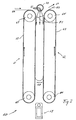
- the structure of a storage device is shown using the example of Feed storage device 16 explained on the feed side by the unwinding speed of the storage roll 15 given feed path speed prevails while on their discharge side in the amount and direction in time with the Embossing intervals varying web speed in the film acceleration area 17 prevails.
- the storage device 16 has on its side facing the film supply 15 first traction device 35 in the form of an elongated suction belt and on the film acceleration device 17 facing discharge side a second traction device 36, the is also formed by an elongated suction belt.
- the two suction belts 35, 36 are identical in construction, with their longitudinal axes parallel to each other in mirror image a dashed line indicated 37 and are perpendicular to the center plane.
- Each of the traction devices has one around two deflection rollers circumferential, perforated conveyor belt 38 and 39, respectively Conveyor belts by a common motor 40 such are driven in opposite directions that their each other facing, flat drive surfaces 41, 42 in one of the lower feed opening upward feed direction 43 (arrows) can be moved at the same speed.
- Conveyor belts by a common motor 40 such are driven in opposite directions that their each other facing, flat drive surfaces 41, 42 in one of the lower feed opening upward feed direction 43 (arrows) can be moved at the same speed.
- Vacuum boxes 45, 46 arranged through the air through the perforations provided in the conveyor belts can be.
- the width of the conveyor belts 38, 39 corresponds a multiple of a film web width, so that several with small distance parallel to each other through the storage device guided embossing foil tracks together in the store can be drawn in.
- Loop section 47 has two parallel to each other straight loop leg 48, which by the suction belts 35, 36 securely guided along their entire length and at a distance to each other by pointing towards 43 moving drive surfaces are pulled, as well as one in Usually short compared to the loop legs, curved free loop section 49 which is not in Is in contact with the suction tapes, but accordingly the supply and discharge-side speed ratios parallel to direction 43 in the area between the positions of maximum and minimum indicated by dashed lines Storage fill can move back and forth.
- the schematic Sensor device 50 shown has a sensor head 51, which in the space between the traction devices 35, 36 directed is and on a cross to the parallel embossing foil webs rail 52 perpendicular to the plane of the paper is movable that the sensor head 51 in succession at the the respective fill state next to each other detected.
- the sensor head has one on the center of the U-shaped curved free loop section 49 directed Laser light source and at least one photocell that the in this area reflected from the film web back 9 Light captured.
- An assigned evaluation device is determined from this the longitudinal distance between the free loop section and the sensor head serving as a reference point.
- the distance measurement over a suitable time interval is carried out, for example, in the Sensor head briefly above the film web to be measured is stopped, is from the temporal development of the Distance also the existing for the respective embossing foil web Filling or emptying speed of the memory derivable.
- the speed is also from the fill levels temporally defined successive path-related individual measurements derivable. The sensor head can do this continuously be moved.
- the film removal storage device 19 is constructed identically, their pulling devices 55, 56 over the same Motor 40 at the same speed as the traction devices 35, 36 are driven and assigned to the suction belts Vacuum boxes connected to the common suction fan 44 are. In contrast to the storage device on the supply side prevails here on the feed side 55 by the Foil acceleration device 17 predetermined non-uniform Belt feed with forward / backward movement while on the Discharge side 56 a uniform discharge to the take-up storage roll 20 takes place.
- FIG. 2 shows a section in a schematic representation by a storage device 60 which is suitable as Foil feed storage device 16 or as a film removal storage device 19 to be used.
- the storage device 60 is formed from the two traction devices 61 and 62 and the fan rail 70.
- the at least one material web 65 is on the startup page 66 of the memory device 60 fed and leaves this on the discharge side 67.
- Each the two pulling devices 61, 62 consist of a pair Casters 64, at least one of which is driven, and a conveyor belt 63.
- the conveyor belt 63 runs around the two rollers 64 of the traction device around.
- the fan rail 70 extends in width across the width of the Conveyor belts 63 and thus determines the width that the may have at least one material web 65 to pass through the To be conveyable through storage device 60.
- the Fan rail 70 has air outlet openings over its entire width 72, from which an air stream emerges which the material web to the conveyor belts 63 of the pulling devices 61, 62 presses. Due to the air flow 71 Material web 65 pressed against the conveyor belts 63 that the material web 65 is moved into the storage device is being exercised, with a steady pull resulting from Airflow 71 flow velocity, movement velocity of conveyor belts 63 and friction between Conveyor belt 63 and material web 65 results.
- the air outlet openings 72 of the fan rail 70 can be in be formed in different ways. It can happen for example around air outlet holes or around air outlet slots act.
- the air outlet openings 72 must be but be designed so that in the area between the traction devices 61 and 62 as uniform as possible, laminar air flow results. Furthermore, the air flow must not only on the space between the train devices 61, 62 aligned, but also on the conveyor belts of the pulling devices must be executed to an adequate extent Contact pressure for the material web 65 on the conveyor belts 63 to reach.
- Detection device 69 is provided, which is the distance to the between the traction devices 61, 62 free loop section 68 of the material web 65 detected. Become multiple webs of material 65 simultaneously in the storage device 60 stored, the detection device 69 is preferred Form so that they are the distance to the free loop sections 68 each web of material either simultaneously or cyclically in succession at a sufficient speed detected. This may be necessary in the detection device 69 to provide several sensors for distance measurement.
- FIG. 3 shows a further exemplary embodiment of a Storage device 60.
- This storage device 60 also essentially consists of two pulling devices 61 and 62 and a fan rail 70 is formed. Unlike that 2 has the pulling device 62 on the outlet side 67 of the at least one material web 65 additionally a suction box 73.
- the at least one Material web 65 is the storage device 60 on the Start page 66 fed. Through the air flow 71, which of the Blower rail 70 is generated, the web of material to the The conveyor belt 76 of the pulling device 61 is pressed. The The conveyor belt 76 of the pulling device 61 moves as well the conveyor belt 63 of the traction device 62 parallel to Air flow direction.
- the enlargement of the Pressure difference corresponds to an increase in the contact pressure of the Material web 65 to the conveyor belt 63 of the traction device 62.
- This measure may also contribute to the Relative movement between the conveyor belt 63 of the traction device 62 and to reduce the at least one material web 65.
- a relative speed between the conveyor belt 63 and the at least one material web 65 consists alone if only because the direction of movement of the conveyor belt 63 opposite to the direction of movement of the material web 65 is directed along the conveyor belt 63.
- blower rail 70 In order to load the material web as evenly as possible To reach 65 through the airflow 71, it can be advantageous be the blower rail 70 at several locations blowing air supply.
- the fan rail 70 can also be in a number divided by segments, each segment using a can have their own air supply, so that the air flow 71 of the through the air outlet openings 72 of the fan rail in Direction toward web 65 exits at everyone Segment can be another. This can then be the case, for example be advantageous if there are several in the storage device 60 Material webs 65 of different characteristics are temporarily stored become.
- a camera 75 On the side of the traction device facing away from the material web 65 61 is as a detection device 69 for the free Loop section 68 of the material web 65 a camera 75 arranged. So that the camera 75 the position of the free loop section between the two pulling devices 61 and 62 can detect, the conveyor belt 76 is transparent educated. The camera has to depend on your Observation opening angle 77 may be arranged so that it the position of the free loop section 68 of the at least a material web 65 between the rollers 64 of the conveyor belt 63 or the transparent conveyor belt 76 can capture. The camera can also extend in the direction of extension the fan rail 70 has such an opening angle or one have such a distance from the transparent conveyor belt 76, that the entire width in the at least one web of material 65 can be performed.
- the camera is in the Position, at the same time the position of the free loop sections 68 of several material webs 65 to be detected. Over a suitable, not shown image evaluation device can then the position as well as the change in position of the free Loop sections 68 are evaluated.
- the camera 75 is thus an example of a detection device 69 that is able to simultaneously position several material webs 65 in the memory device 60.
- the loop section over the substantial part of its length, with the exception of the free Loop section, guided and held securely so that especially touching the loop legs, for example due to electrostatic attraction, reliable is avoided.
- the non-guided, free loop section on the other hand stands calmly and flutter-free between the Suction belts and can be used as a well-detectable reference surface for the distance measurement using the one aimed at him Serve sensor device.
- the positionally reliable web guide can be guaranteed without special sealing measures, such as they are required for vacuum accumulators.
- foil webs of other widths without Effort possible because there are no side walls that limit the path must be provided.
- the storage capacity of the film storage to determine the total length of feed of the store that it is not for memory overcrowding or for complete Emptying of the memory can come.
- the storage dimension can be reduced by filling and / or filling or emptying speed of a memory by means of the Sensor device 50 monitors and, for example, the rolling speed the unwind storage roll 15 depending is controlled by filling level and / or filling speed.
- On Distance sensor is particularly advantageous for this, because not only the absolute levels, given by the (vertical) Position of the free loop section, detected can be, but by observing the temporal Course of the distance in particular also filling and emptying speeds.
Claims (18)
- Moyen d'accumulation (16, 19) pour le logement d'une section de boucle d'au moins une bande de matériau (8) flexible en déplacement, notamment d'une bande de feuille à empreindre, entre un domaine d'alimentation mis en précascade sur le moyen d'accumulation, dans lequel domaine cette bande de matériau au moins est déplacée avec une vitesse de bande d'alimentation, et un domaine d'évacuation placé dans la suite, dans lequel domaine la bande de matériau (8) est déplacée avec une vitesse de bande d'évacuation différant au moins temporairement de la vitesse de bande d'alimentation, caractérisé en ce que le moyen d'accumulation (16, 19, 60) présente côté admission un premier moyen de traction (35, 55) pour entraíner la bande de matériau vers l'intérieur du moyen d'accumulation et côté éduction un deuxième moyen de traction (36, 56) distinct pour faire entrer la bande de matériau dans le moyen d'accumulation.
- Moyen d'accumulation d'après la revendication 1, caractérisé en ce que le premier moyen de traction (35, 55) et/ou le deuxième moyen de traction (36, 56) présente au moins une surface d'entraínement (41, 42) de préférence plane par sections, pouvant être déplacée dans une direction de rentrage (43) ainsi que des moyens de pression (44, 45, 46) pour serrer la bande de matériau par la surface à la surface d'entraínement, une vitesse de la surface d'entraínement étant en direction de rentrage de préférence plus grande que la vitesse en direction de rentrage de la bande de matériau (8) adjacente.
- Moyen d'accumulation d'après la revendication 1 ou 2, caractérisé en ce que le premier moyen de traction (35, 55) et/ou le deuxième moyen de traction (36, 56) présente au moins une courroie de transport (38, 39) à rotation, formant la surface d'entraínement (41, 42) respectivement avec une section plane de sa surface extérieure.
- Moyen d'accumulation d'après une des revendications 2 ou 3, caractérisé en ce que les moyens de pression comprennent au moins un moyen d'aspiration (44, 45, 46) pour l'aspiration de une bande de matériau (8) au moins contre la surface d'entraínement (41, 42).
- Moyen d'accumulation d'après une des revendications précédentes, caractérisé en ce que entre le premier et le deuxième moyen de traction est disposée une barre à soufflerie (70), la barre à soufflerie (70) présentant au moins une ouverture d'échappement d'air (72) pour un courant d'air (71) pour le pressage de cette bande de matériau (65) au moins sur les moyens de traction (35, 55, 61 ; 36, 56, 62).
- Moyen d'accumulation d'après la revendication 5, caractérisé en ce que le courant d'air (71) présente un écoulement laminaire.
- Moyen d'accumulation d'après une des revendications précédentes, caractérisé en ce que le premier moyen de traction (35, 36) et le deuxième moyen de traction (55, 56) présentent des surfaces d'entraínement (41, 42) étant l'une en face de l'autre et/ou s'étendant essentiellement de manière parallèle l'une par rapport à l'autre.
- Moyen d'accumulation d'après une des revendications précédentes, caractérisé en ce que l'on prévoit des moyens de réglage pour la force de traction qui agit par le premier moyen de traction et/ou par le deuxième moyen de traction sur au moins une bande de matériau, la force de succion d'un moyen d'aspiration et/ou la vitesse de déplacement d'une surface d'entraínement étant de préférence réglable.
- Moyen d'accumulation d'après le préambule de la revendication 1, notamment d'après une des revendications précédentes, caractérisé en ce que l'on prévoit un moyen de détection (50), présentant au moins un détecteur écartométrique pour capter un écart entre une section de partie de boucle libre (49, 68) de la section de boucle et un point de référence.
- Moyen d'accumulation d'après la revendication 9, caractérisé en ce que le moyen de détection (50) est réalisé pour la captage d'une vitesse de modification de la charge d'accumulateur.
- Moyen d'accumulation d'après la revendication 9 ou 10, caractérisé en ce que le moyen de détection présente au moins un moyen émetteur (51) pouvant être orienté en direction d'une section de partie de boucle libre (49) pour la génération d'ondes électromagnétiques et/ou acoustiques, et de préférence au moins un moyen récepteur pour la réception d'ondes réfléchies par la section de partie de boucle (49).
- Moyen d'accumulation d'après la revendication 11, caractérisé en ce que le moyen émetteur (51) présente au moins une source de lumière laser et/ou que le moyen récepteur présente au moins une photodiode.
- Moyen d'accumulation d'après la revendication 9, caractérisé en ce que le moyen de détection (50, 69) est constitué par une caméra (75).
- Moyen d'accumulation d'après la revendication 13, caractérisé en ce que la courroie de transport (76) du moyen de traction (61) est transparente et en ce que la caméra (75) est disposée sur le côté, opposé à une bande de matériau (65) au moins, du moyen de traction (61).
- Moyen d'accumulation d'après une des revendications précédentes, caractérisé en ce qu'il est réalisé pour l'accumulation de plusieurs bandes de matériau parallèles, pouvant être déplacées de préférence indépendamment l'une de l'autre et en ce que le moyen de détection (50) présente au moins un capteur, qui peut être déplacé entre les domaines de bande de matériau pour au moins deux bandes de matériau parallèlement mobiles pour la détection temporellement consécutive de l'état de la charge d'accumulateur.
- Dispositif d'estampage, notamment dispositif d'estampage à chaud, avec un organe d'estampage (2), pour lequel est formé une fente d'estampage (5) entre un cylindre d'estampage (3) et un élément de contre-pression, notamment un cylindre de contre-pression (4), et avec un dispositif de transport pour le transport d'au moins une bande de feuille à empreindre à partir d'une réservoir à feuilles (15) à travers la fente d'estampage (5) vers un moyen collecteur de feuilles (20), le dispositif de transport présentant des moyens d'accélération de feuilles (17) réalisés de telle manière, que la bande de feuilles à empreindre se déplace à travers la fente d'estampage à la même vitesse qu'une bande de matériau à estamper au moins pendant l'intervalle d'estampage, caractérisé en ce qu'entre le réservoir à feuilles(15) et les moyens d'accélération de feuilles (17) et/ou entre les moyens d'accélération de feuilles (17) et le moyen collecteur de feuilles (20) est disposé au moins un moyen d'accumulation (16, 19) d'après une des revendications de 1 à 11.
- Dispositif d'estampage d'après la revendication 16, caractérisé en ce que les moyens d'accélération de feuilles (17) sont réalisés pour la production d'un mouvement non-uniforme d'au moins une bande de matériau (8), de préférence pour la production d'un mouvement d'avance / en retour, dans lequel la bande de matériau est déplacée temporairement dans une direction en retour opposée à la direction de transport principale (18).
- Dispositif d'estampage d'après la revendication 16 ou 17, caractérisé en ce que le réservoir à feuilles, qui comprend de préférence une bobine débitrice d'accumulation (15) pour la bande de feuille à empreindre, peut être commandé par rapport au taux de dévidement, de préférence en fonction du degré de remplissage et/ou d'une vitesse de modification de l'état de remplissage d'un moyen d'accumulation (16) placé après le réservoir à feuilles.
Applications Claiming Priority (2)
| Application Number | Priority Date | Filing Date | Title |
|---|---|---|---|
| DE19842585 | 1998-09-17 | ||
| DE19842585A DE19842585A1 (de) | 1998-09-17 | 1998-09-17 | Speichereinrichtung und ihre Verwendung |
Publications (2)
| Publication Number | Publication Date |
|---|---|
| EP0987205A1 EP0987205A1 (fr) | 2000-03-22 |
| EP0987205B1 true EP0987205B1 (fr) | 2003-06-18 |
Family
ID=7881270
Family Applications (1)
| Application Number | Title | Priority Date | Filing Date |
|---|---|---|---|
| EP99117630A Expired - Lifetime EP0987205B1 (fr) | 1998-09-17 | 1999-09-07 | Accumulateur à boucle pour matériau en bande et son utilisation |
Country Status (6)
| Country | Link |
|---|---|
| US (1) | US6230616B1 (fr) |
| EP (1) | EP0987205B1 (fr) |
| AT (1) | ATE243157T1 (fr) |
| DE (2) | DE19842585A1 (fr) |
| DK (1) | DK0987205T3 (fr) |
| ES (1) | ES2201607T3 (fr) |
Cited By (2)
| Publication number | Priority date | Publication date | Assignee | Title |
|---|---|---|---|---|
| EP1683635A1 (fr) | 2005-01-19 | 2006-07-26 | Steuer GmbH Printing Technology | Procedée et appareil pour éliminer de materiau flexible en forme de bande |
| DE102019106702A1 (de) * | 2019-03-15 | 2020-09-17 | Chromasens Gmbh | Bahnbeobachtungssystem und Verfahren zur Bahnbeobachtung |
Families Citing this family (34)
| Publication number | Priority date | Publication date | Assignee | Title |
|---|---|---|---|---|
| DE10024057A1 (de) * | 2000-05-16 | 2001-11-29 | Lemo Maschb Gmbh | Taktweise arbeitende Maschine, insbesondere Maschine zum Herstellen von Beuteln oder dergleichen |
| DE10023888A1 (de) * | 2000-05-17 | 2001-11-22 | Armin Steuer | Heißprägeverfahren und Heißprägevorrichtung |
| JP3944829B2 (ja) | 2002-01-17 | 2007-07-18 | ソニー株式会社 | 固体撮像装置およびその駆動方法 |
| DE10231323B4 (de) * | 2002-07-11 | 2005-09-29 | Koenig & Bauer Ag | Vorrichtung zur Messung einer Lage von Materialbahnen |
| US7093939B2 (en) * | 2004-04-05 | 2006-08-22 | Nextscan, Inc. | High-speed continuous linear film transport system |
| ITMI20041223A1 (it) * | 2004-06-17 | 2004-09-17 | No El Srl | Metodo ed apparecchiatura per la produzione di bobine senz'anima in film plastico |
| DE102005046689A1 (de) * | 2005-09-29 | 2007-04-05 | Heidelberger Druckmaschinen Ag | Folienübertragungsvorrichtung |
| WO2008077496A2 (fr) * | 2006-12-20 | 2008-07-03 | Manroland Ag | Ensemble de film modulaire |
| FR2913914B1 (fr) * | 2007-03-21 | 2012-09-07 | Cer | Machine de marquage a ruban |
| PL1975101T3 (pl) | 2007-03-28 | 2012-10-31 | Heidelberger Druckmasch Ag | Nawijanie pasma folii transferowej |
| EP1980516B1 (fr) * | 2007-04-13 | 2011-11-02 | WIFAG Maschinenfabrik AG | Procédé de mesure et dispositif de détermination de la position de bandes de matériau |
| EP2100735A1 (fr) * | 2008-01-21 | 2009-09-16 | Vinfoil B.V. | Dispositif d'alimentation de film à utiliser dans un processus d'impression vers une presse d'impression |
| DE102008011493A1 (de) * | 2008-02-20 | 2009-08-27 | Spm Steuer Gmbh & Co. Kg | Verfahren zur Entsorgung von verbrauchter Prägefolienbahn sowie Prägevorrichtung mit kontinuierlich arbeitender Entsorgungseinrichtung |
| JP2009208308A (ja) * | 2008-03-03 | 2009-09-17 | Miyakoshi Printing Machinery Co Ltd | 箔転写装置 |
| CN102046382B (zh) * | 2008-05-28 | 2013-07-24 | 曼罗兰纸张有限责任公司 | 用于冷薄膜压印的装置 |
| DE102009021176A1 (de) * | 2009-05-13 | 2010-11-18 | Hans Mathea | Vorrichtung zum Bedrucken einer Materialbahn |
| DE102010028836A1 (de) * | 2010-05-11 | 2011-11-17 | Manroland Ag | Folienspeicher in einer Vorrichtung zum Kaltfolienprägen |
| DE102010037285A1 (de) * | 2010-09-02 | 2012-03-08 | Krones Aktiengesellschaft | Einrichtung und Verfahren zum Fördern eines Etikettenbands sowie Etikettieraggregat |
| US9694573B2 (en) | 2010-12-17 | 2017-07-04 | Diversified Graphic Machinery | Cold foil printing system and method |
| CN102896890A (zh) * | 2011-07-27 | 2013-01-30 | 上海亚华印刷机械有限公司 | 一种具备铝箔储存装置的烫印机 |
| CN103029425B (zh) | 2011-10-07 | 2015-07-29 | 小森公司 | 薄膜转印装置 |
| CN102530619B (zh) * | 2012-01-12 | 2015-08-19 | 天津长荣印刷设备股份有限公司 | 一种储料装置及其工作方法 |
| US10029876B2 (en) * | 2012-04-27 | 2018-07-24 | Web Industries, Inc. | Interliner method and apparatus |
| US10093506B2 (en) | 2013-07-01 | 2018-10-09 | Bobst Mex Sa | Braking device for a tape reel |
| GB201419961D0 (en) * | 2014-11-10 | 2014-12-24 | Hitch David | Apparatus for printing onto objects |
| CN104354469A (zh) * | 2014-11-19 | 2015-02-18 | 温州力冠机械有限公司 | 印刷品自动剔废组件 |
| CN104354468A (zh) * | 2014-11-19 | 2015-02-18 | 温州力冠机械有限公司 | 印刷品自动剔废复原装置 |
| CN104354470A (zh) * | 2014-11-19 | 2015-02-18 | 温州力冠机械有限公司 | 印刷品自动复原组件 |
| WO2018086712A1 (fr) * | 2016-11-14 | 2018-05-17 | Sidel Participations | Appareil d'étiquetage et procédé de fonctionnement d'un tel appareil d'étiquetage |
| JP7055408B2 (ja) * | 2019-10-30 | 2022-04-18 | 株式会社ミヤコシ | 転写装置及びその転写方法 |
| JP7055407B2 (ja) * | 2019-10-30 | 2022-04-18 | 株式会社ミヤコシ | 転写装置及びその転写方法 |
| CN113371511A (zh) * | 2021-07-15 | 2021-09-10 | 深圳吉阳智能科技有限公司 | 一种张力控制系统以及张力控制方法 |
| DE102021129745A1 (de) * | 2021-11-15 | 2023-05-17 | Manroland Goss Web Systems Gmbh | Formatvariable Stanzvorrichtung und Verfahren hierzu |
| CN114873340A (zh) * | 2022-04-14 | 2022-08-09 | 中国原子能科学研究院 | 用于测量核孔膜的物理参数的设备和方法 |
Family Cites Families (11)
| Publication number | Priority date | Publication date | Assignee | Title |
|---|---|---|---|---|
| DE2146038C3 (de) * | 1971-09-15 | 1981-07-23 | Albert-Frankenthal Ag, 6710 Frankenthal | Vorrichtung zum Transport einer Bahn in Druckmaschinen mit inermittierendem Transport der Bahn |
| BE786186A (fr) * | 1972-05-23 | 1973-01-12 | Ruesch Ferd Maschf | Dispositif pour deplacer une bande dans une machine d'impression rotative pour des impressions de formats |
| US3784071A (en) * | 1973-04-02 | 1974-01-08 | Goodyear Tire & Rubber | Variable length festooning of web material |
| FR2280516A1 (fr) * | 1974-07-31 | 1976-02-27 | Sublistatic Holding Sa | Procede et installation pour realiser une bande de transfert grande laize |
| IT1184341B (it) | 1984-03-29 | 1987-10-28 | Hauni Werke Koerber & Co Kg | Dispositivo per alimentare materiale di rivestimento ad involucro ad una confezionatrice,specialmente confezionatrice per sigarette |
| US4640191A (en) * | 1985-08-13 | 1987-02-03 | Bradley Gerald R | Sublimation printing apparatus |
| FR2623127A1 (fr) * | 1987-11-12 | 1989-05-19 | Sarda Jean Claude | Dispositif d'alimentation et de reception d'une bande continue destine aux presses a imprimer du type feuille a feuille |
| DE4411936C2 (de) * | 1994-04-07 | 1996-03-28 | Fischer Maschf Karl E | Vorrichtung zum Auflagern und Führen eines zu bearbeitenden Bandmaterials im Schlaufenbereich |
| DE9420707U1 (de) * | 1994-12-24 | 1995-02-16 | Steuer Armin | Präge-Rotationsmaschine |
| DE59805462D1 (de) * | 1997-02-13 | 2002-10-17 | Gietz Ag Gossau Maschf | Flach-Prägedruckmaschine |
| US5873662A (en) * | 1997-12-03 | 1999-02-23 | Illinois Tool Works Inc. | Printer with dancer arm and reel brake and method therefor |
-
1998
- 1998-09-17 DE DE19842585A patent/DE19842585A1/de not_active Withdrawn
-
1999
- 1999-09-07 AT AT99117630T patent/ATE243157T1/de not_active IP Right Cessation
- 1999-09-07 ES ES99117630T patent/ES2201607T3/es not_active Expired - Lifetime
- 1999-09-07 DE DE59905984T patent/DE59905984D1/de not_active Expired - Lifetime
- 1999-09-07 EP EP99117630A patent/EP0987205B1/fr not_active Expired - Lifetime
- 1999-09-07 DK DK99117630T patent/DK0987205T3/da active
- 1999-09-14 US US09/395,165 patent/US6230616B1/en not_active Expired - Lifetime
Cited By (3)
| Publication number | Priority date | Publication date | Assignee | Title |
|---|---|---|---|---|
| EP1683635A1 (fr) | 2005-01-19 | 2006-07-26 | Steuer GmbH Printing Technology | Procedée et appareil pour éliminer de materiau flexible en forme de bande |
| DE102019106702A1 (de) * | 2019-03-15 | 2020-09-17 | Chromasens Gmbh | Bahnbeobachtungssystem und Verfahren zur Bahnbeobachtung |
| EP3718728A1 (fr) | 2019-03-15 | 2020-10-07 | Chromasens GmbH | Système de surveillance de bande et procédé de surveillance de bande |
Also Published As
| Publication number | Publication date |
|---|---|
| DK0987205T3 (da) | 2003-10-13 |
| DE59905984D1 (de) | 2003-07-24 |
| US6230616B1 (en) | 2001-05-15 |
| EP0987205A1 (fr) | 2000-03-22 |
| ATE243157T1 (de) | 2003-07-15 |
| ES2201607T3 (es) | 2004-03-16 |
| DE19842585A1 (de) | 2000-03-23 |
Similar Documents
| Publication | Publication Date | Title |
|---|---|---|
| EP0987205B1 (fr) | Accumulateur à boucle pour matériau en bande et son utilisation | |
| EP0718099B1 (fr) | Machine rotative pour gaufrer | |
| EP0858888B2 (fr) | Presse d'estampage à plat | |
| EP1947223B1 (fr) | Dispositf pour le transport guidé d'un voile de fibres | |
| EP2093057B1 (fr) | Procédé et dispositif d'élimination d'une bande d'estampage usagée | |
| EP2175056B1 (fr) | Dispositif et procédé destinés à la transmission d'un non-tissé | |
| DE3713666C2 (de) | Verfahren zum Aufprägen und Präge-Rotationsmaschine | |
| DE3820032A1 (de) | Interfolder mit den faltwalzen nachgeschalteter staustrecke | |
| DE4435988A1 (de) | Vorrichtung zum Abbremsen von Bogen | |
| DE69817018T2 (de) | Gerät zum aktiven stabilisieren einer bahn | |
| DE1957485A1 (de) | Verfahren zur Messung der Bahnspannung | |
| EP0697989B1 (fr) | Dispositif permettant de transferer et d'empiler des feuilles | |
| WO1997011019A1 (fr) | Procede et dispositif de production d'imprimes | |
| DE19911273C2 (de) | Verfahren und Vorrichtung zum Vereinzeln flächiger Güter | |
| DE2256882A1 (de) | Papierbahndehnungsregelung und vorrichtung zur durchfuehrung derselben | |
| EP0523346A1 (fr) | Dispositif de transport d'une bande de papier dans une plieuse pour une presse d'impression | |
| DE102011011659A1 (de) | Antriebsmechanismus für eine Vorrichtung zum Legen einer Fasermaterialbahn in eine Leporellofaltung | |
| DE19506463C2 (de) | Stauüberwachungseinrichtung für eine Transportvorrichtung für Papier, insbesondere für eine Papierbahn | |
| DE4314756C2 (de) | Vorrichtung zum Schuppen und Ablegen von Bogen auf einen Stapel | |
| DE1202118B (de) | Vorrichtung zum intermittierenden Foerdern von aus einer Stanze herauskommenden Bahnen oder Bahnteilen aus Papier, Karton od. dgl. | |
| DE2407848C2 (de) | Vorrichtung zum Einebnen und ebenflächigen Weiterführen von einer oder mehreren in Papierverarbeitungsmaschinen freischwebend geführten Materialbahnen | |
| DE102007032911A1 (de) | Verfahren zum Betrieb eines Längsfalzapparates | |
| WO2006099838A1 (fr) | Procede et dispositif pour deposer une bande de matiere souple | |
| DE102008025667A1 (de) | Fördereinrichtung für Bogenlagen und Verfahren zum Bilden und Fördern eines Schuppenstroms aus Bogenlagen | |
| DE2822137A1 (de) | Bahnfoermiges material verarbeitende maschine |
Legal Events
| Date | Code | Title | Description |
|---|---|---|---|
| PUAI | Public reference made under article 153(3) epc to a published international application that has entered the european phase |
Free format text: ORIGINAL CODE: 0009012 |
|
| AK | Designated contracting states |
Kind code of ref document: A1 Designated state(s): AT BE CH CY DE DK ES FI FR GB GR IE IT LI LU MC NL PT SE |
|
| AX | Request for extension of the european patent |
Free format text: AL;LT;LV;MK;RO;SI |
|
| 17P | Request for examination filed |
Effective date: 20000826 |
|
| AKX | Designation fees paid |
Free format text: AT BE CH CY DE DK ES FI FR GB GR IE IT LI LU MC NL PT SE |
|
| 17Q | First examination report despatched |
Effective date: 20020731 |
|
| GRAH | Despatch of communication of intention to grant a patent |
Free format text: ORIGINAL CODE: EPIDOS IGRA |
|
| GRAH | Despatch of communication of intention to grant a patent |
Free format text: ORIGINAL CODE: EPIDOS IGRA |
|
| GRAA | (expected) grant |
Free format text: ORIGINAL CODE: 0009210 |
|
| AK | Designated contracting states |
Designated state(s): AT BE CH CY DE DK ES FI FR GB GR IE IT LI LU MC NL PT SE |
|
| PG25 | Lapsed in a contracting state [announced via postgrant information from national office to epo] |
Ref country code: IE Free format text: LAPSE BECAUSE OF FAILURE TO SUBMIT A TRANSLATION OF THE DESCRIPTION OR TO PAY THE FEE WITHIN THE PRESCRIBED TIME-LIMIT Effective date: 20030618 Ref country code: FI Free format text: LAPSE BECAUSE OF FAILURE TO SUBMIT A TRANSLATION OF THE DESCRIPTION OR TO PAY THE FEE WITHIN THE PRESCRIBED TIME-LIMIT Effective date: 20030618 |
|
| REG | Reference to a national code |
Ref country code: GB Ref legal event code: FG4D Free format text: NOT ENGLISH |
|
| REG | Reference to a national code |
Ref country code: SE Ref legal event code: TRGR |
|
| REG | Reference to a national code |
Ref country code: CH Ref legal event code: EP |
|
| REG | Reference to a national code |
Ref country code: CH Ref legal event code: NV Representative=s name: WERNER FENNER PATENTANWALT |
|
| REG | Reference to a national code |
Ref country code: IE Ref legal event code: FG4D Free format text: GERMAN |
|
| REF | Corresponds to: |
Ref document number: 59905984 Country of ref document: DE Date of ref document: 20030724 Kind code of ref document: P |
|
| GBT | Gb: translation of ep patent filed (gb section 77(6)(a)/1977) | ||
| PG25 | Lapsed in a contracting state [announced via postgrant information from national office to epo] |
Ref country code: LU Free format text: LAPSE BECAUSE OF NON-PAYMENT OF DUE FEES Effective date: 20030907 Ref country code: CY Free format text: LAPSE BECAUSE OF FAILURE TO SUBMIT A TRANSLATION OF THE DESCRIPTION OR TO PAY THE FEE WITHIN THE PRESCRIBED TIME-LIMIT Effective date: 20030907 |
|
| PG25 | Lapsed in a contracting state [announced via postgrant information from national office to epo] |
Ref country code: PT Free format text: LAPSE BECAUSE OF FAILURE TO SUBMIT A TRANSLATION OF THE DESCRIPTION OR TO PAY THE FEE WITHIN THE PRESCRIBED TIME-LIMIT Effective date: 20030918 |
|
| PG25 | Lapsed in a contracting state [announced via postgrant information from national office to epo] |
Ref country code: MC Free format text: LAPSE BECAUSE OF NON-PAYMENT OF DUE FEES Effective date: 20030930 Ref country code: BE Free format text: LAPSE BECAUSE OF NON-PAYMENT OF DUE FEES Effective date: 20030930 |
|
| REG | Reference to a national code |
Ref country code: GR Ref legal event code: EP Ref document number: 20030403620 Country of ref document: GR |
|
| REG | Reference to a national code |
Ref country code: IE Ref legal event code: FD4D |
|
| REG | Reference to a national code |
Ref country code: ES Ref legal event code: FG2A Ref document number: 2201607 Country of ref document: ES Kind code of ref document: T3 |
|
| BERE | Be: lapsed |
Owner name: *STEUER ARMIN Effective date: 20030930 |
|
| PLBE | No opposition filed within time limit |
Free format text: ORIGINAL CODE: 0009261 |
|
| STAA | Information on the status of an ep patent application or granted ep patent |
Free format text: STATUS: NO OPPOSITION FILED WITHIN TIME LIMIT |
|
| ET | Fr: translation filed | ||
| 26N | No opposition filed |
Effective date: 20040319 |
|
| PGFP | Annual fee paid to national office [announced via postgrant information from national office to epo] |
Ref country code: NL Payment date: 20050919 Year of fee payment: 7 |
|
| PGFP | Annual fee paid to national office [announced via postgrant information from national office to epo] |
Ref country code: AT Payment date: 20050922 Year of fee payment: 7 |
|
| PGFP | Annual fee paid to national office [announced via postgrant information from national office to epo] |
Ref country code: SE Payment date: 20050923 Year of fee payment: 7 |
|
| PGFP | Annual fee paid to national office [announced via postgrant information from national office to epo] |
Ref country code: DK Payment date: 20050926 Year of fee payment: 7 |
|
| PGFP | Annual fee paid to national office [announced via postgrant information from national office to epo] |
Ref country code: GR Payment date: 20050927 Year of fee payment: 7 |
|
| PG25 | Lapsed in a contracting state [announced via postgrant information from national office to epo] |
Ref country code: AT Free format text: LAPSE BECAUSE OF NON-PAYMENT OF DUE FEES Effective date: 20060907 |
|
| PG25 | Lapsed in a contracting state [announced via postgrant information from national office to epo] |
Ref country code: SE Free format text: LAPSE BECAUSE OF NON-PAYMENT OF DUE FEES Effective date: 20060908 |
|
| PGFP | Annual fee paid to national office [announced via postgrant information from national office to epo] |
Ref country code: ES Payment date: 20060926 Year of fee payment: 8 |
|
| PGFP | Annual fee paid to national office [announced via postgrant information from national office to epo] |
Ref country code: IT Payment date: 20060930 Year of fee payment: 8 |
|
| PG25 | Lapsed in a contracting state [announced via postgrant information from national office to epo] |
Ref country code: DK Free format text: LAPSE BECAUSE OF NON-PAYMENT OF DUE FEES Effective date: 20061002 |
|
| PG25 | Lapsed in a contracting state [announced via postgrant information from national office to epo] |
Ref country code: NL Free format text: LAPSE BECAUSE OF NON-PAYMENT OF DUE FEES Effective date: 20070401 |
|
| REG | Reference to a national code |
Ref country code: DK Ref legal event code: EBP |
|
| EUG | Se: european patent has lapsed | ||
| NLV4 | Nl: lapsed or anulled due to non-payment of the annual fee |
Effective date: 20070401 |
|
| PG25 | Lapsed in a contracting state [announced via postgrant information from national office to epo] |
Ref country code: GR Free format text: LAPSE BECAUSE OF NON-PAYMENT OF DUE FEES Effective date: 20070404 |
|
| REG | Reference to a national code |
Ref country code: ES Ref legal event code: FD2A Effective date: 20070908 |
|
| PG25 | Lapsed in a contracting state [announced via postgrant information from national office to epo] |
Ref country code: ES Free format text: LAPSE BECAUSE OF NON-PAYMENT OF DUE FEES Effective date: 20070908 |
|
| PG25 | Lapsed in a contracting state [announced via postgrant information from national office to epo] |
Ref country code: IT Free format text: LAPSE BECAUSE OF NON-PAYMENT OF DUE FEES Effective date: 20070907 |
|
| REG | Reference to a national code |
Ref country code: CH Ref legal event code: PFA Owner name: STEUER, ARMIN Free format text: STEUER, ARMIN#AM WALDRAND 30#D-71111 WALDENBUCH (DE) -TRANSFER TO- STEUER, ARMIN#AM WALDRAND 30#D-71111 WALDENBUCH (DE) |
|
| REG | Reference to a national code |
Ref country code: DE Ref legal event code: R082 Ref document number: 59905984 Country of ref document: DE Representative=s name: PATENTANWAELTE RUFF, WILHELM, BEIER, DAUSTER &, DE Ref country code: DE Ref legal event code: R082 Ref document number: 59905984 Country of ref document: DE |
|
| REG | Reference to a national code |
Ref country code: DE Ref legal event code: R082 Ref document number: 59905984 Country of ref document: DE |
|
| REG | Reference to a national code |
Ref country code: CH Ref legal event code: NV Representative=s name: WAGNER PATENT AG, CH |
|
| REG | Reference to a national code |
Ref country code: FR Ref legal event code: PLFP Year of fee payment: 18 |
|
| REG | Reference to a national code |
Ref country code: FR Ref legal event code: PLFP Year of fee payment: 19 |
|
| REG | Reference to a national code |
Ref country code: FR Ref legal event code: PLFP Year of fee payment: 20 |
|
| PGFP | Annual fee paid to national office [announced via postgrant information from national office to epo] |
Ref country code: FR Payment date: 20180914 Year of fee payment: 20 Ref country code: DE Payment date: 20180828 Year of fee payment: 20 |
|
| PGFP | Annual fee paid to national office [announced via postgrant information from national office to epo] |
Ref country code: CH Payment date: 20180912 Year of fee payment: 20 Ref country code: GB Payment date: 20180905 Year of fee payment: 20 |
|
| REG | Reference to a national code |
Ref country code: DE Ref legal event code: R071 Ref document number: 59905984 Country of ref document: DE |
|
| REG | Reference to a national code |
Ref country code: CH Ref legal event code: PL |
|
| REG | Reference to a national code |
Ref country code: GB Ref legal event code: PE20 Expiry date: 20190906 |
|
| PG25 | Lapsed in a contracting state [announced via postgrant information from national office to epo] |
Ref country code: GB Free format text: LAPSE BECAUSE OF EXPIRATION OF PROTECTION Effective date: 20190906 |