EP0856246B1 - Broyeuse secondaire - Google Patents
Broyeuse secondaire Download PDFInfo
- Publication number
- EP0856246B1 EP0856246B1 EP98100939A EP98100939A EP0856246B1 EP 0856246 B1 EP0856246 B1 EP 0856246B1 EP 98100939 A EP98100939 A EP 98100939A EP 98100939 A EP98100939 A EP 98100939A EP 0856246 B1 EP0856246 B1 EP 0856246B1
- Authority
- EP
- European Patent Office
- Prior art keywords
- sections
- diameter
- crushing device
- rolls
- roller
- Prior art date
- Legal status (The legal status is an assumption and is not a legal conclusion. Google has not performed a legal analysis and makes no representation as to the accuracy of the status listed.)
- Expired - Lifetime
Links
Images

Classifications
-
- A—HUMAN NECESSITIES
- A01—AGRICULTURE; FORESTRY; ANIMAL HUSBANDRY; HUNTING; TRAPPING; FISHING
- A01D—HARVESTING; MOWING
- A01D82/00—Crop conditioners, i.e. machines for crushing or bruising stalks
- A01D82/02—Rollers for crop conditioners
Definitions
- the invention relates to a shredding device for chopped crop-well with at least two rollers, the rollers with parallel to each other and to an axis of rotation Circumferential surfaces are provided, each of the roller sections small and Has large diameter sections, the large sections and sections of small diameter of the opposite Enter the roller to form a shear edge on the end faces and peripheral surfaces of the rollers have a tooth profile.
- DE-OS-26 21 292 discloses the example of an attached Corn chopper in the exemplary embodiment according to FIGS. 3 and 4 two intermeshing rollers, which have a variety on their length of externally toothed washers that are spaced apart exhibit. Attached to the opposite roller in the same Discs formed in this way enter the spaces between the Discs of the roller on this side. Between the outer surface of the Discs on the one hand and the outer surface of the roller in the area of On the other hand, there is a gap in the valley which opens up in the Grains contained in the crop prevented.
- the larger diameter sections of one Roller and the smaller diameter sections of the others Rollers can be formed with the same outside diameter be, where then the rollers with at different speeds around you to achieve additional splice effect. However, they can Rolling at the same speed different outside diameter. Finally results with sections of different outside diameters same speed always a speed difference.
- the slit-shaped sections of small diameter can be used as small grooves are screwed or inserted into a roller or by using spacers between two neighboring ones Sections of a roller are formed. Otherwise you can with separate sections arranged side by side be in one or both sections also in Side area recesses are chamfered.
- the cutting effect is obtained as long as possible if as Cutting disc formed sections of large diameter the sections formed as slots Diameter slide along what z. B. by a slight axial misalignment of both rollers or the Sections is reachable.
- the shear edge is on the End faces or side surfaces of two preferably the same formed broad sections of opposing rollers.
- the side surfaces slide with the least possible Distance to each other and cut possibly contained in the feed Leaves.
- Rolls of different widths can be built using modular technology are formed when the sections as full disks are formed and by clamping screws on a shaft be summarized. Depending on the number of sections there are different roller widths.
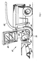
- a harvesting machine 10 shown in FIG. 1 in the manner of a self-propelled forage harvester is built on a frame 12 on carried by front and rear wheels 14 and 16 becomes.
- the harvesting machine 10 is operated by a Driver's cab 18, from which a crop receiving device 20 is visible.
- goods picked up from the ground e.g. B. corn, grass or the like is fed to a chopper drum 22, which it in small Chops pieces and gives it to a conveyor 24.
- the Well the harvesting machine 10 leaves for a vehicle traveling alongside Trailer over a rotating discharge shaft 26.
- the location the post-shredding device 28, however, is not crucial so that they are also downstream of the Conveyor 24 can be provided.
- the post-shredding device 28 is in the essentially formed by two rollers 30, the axes of rotation run parallel to each other and the one between them Leave gap 32 through which the harvested crop passes.
- the two rollers 30 can be the same or turn different speed and serve the good to squeeze the gap 32 passing and / or continue to mince.
- the gap 32 can vary depending on the harvesting conditions be set wide, which is not the case in the drawing illustrated devices known in the prior art be used.
- Each roller 30 includes a continuous shaft 34; instead can also wave stub or only part of the length running waves are used. Both waves 34 are with equipped a drive wheel, not shown, over which the Rollers 30 set in rotation in the opposite direction become. The ends of the shafts 34 are in bearings, not shown a carrier or rotatable in the side walls of a housing added.
- each roller 30 has a plurality of sections large diameter 36 and small diameter portions 38 provided, which is arranged coaxially to the axis of rotation of the shaft 34 are a closed surface along the entire length form that serve the good processing.
- the large and small diameter sections 36 and 38 connect to each other at the ends and are not by means shown clamping screws, clamping anchors, wedges, clamping nuts or the like on the shaft 34, against each other or on one Carrier roll not shown attached.
- the arrangement of the large and small diameter sections 36, 38 is made so that they are radially the same Have dimensions. Furthermore, the respective sections 36, 38 arranged offset from one another so that they are one inside the other intervene, d. that is, the large diameter portion 36 one roller 34 opposite the small section Diameter 38 of the opposite roller 30 to lie comes and dives into this valley.
- the interlocking of the Sections 36, 38 are made so that end faces 40 are adjacent Sections 36, 38 with the smallest possible gap or even without Rub the gap together, so that a shear edge at The end faces 40 meet.
- the tooth profile 42 is designed that the tooth gaps are smaller than contained in the good Grains so that in the gap 32 between opposite Rolls 30 entering grains, e.g. B. corn kernels, crushed become.
- the tooth depth is approx. 5 mm
- the diameter difference between the two sections is at least 10 mm and the width of the sections about 25 mm.
- the teeth and Tooth gaps extend in the longitudinal direction of the shaft 34 and roller 30 and extend to that of the opposite one Roller 30 in parallel.
- sections 36 and 38 are of equal width, they slide End faces 40 together.
- sections 36 and 38 made of solid material and extend from the tooth profile 42 to the shaft 34 on which it are attached directly or indirectly in a rotationally fixed manner. Indeed are the sections 36, 38 only in the area of their tooth profile hardened. After a first deviation, the sections 36, 38 in the area between the tooth profile 42 and the shaft 34 can also be designed as spokes. After another Deviation, the sections 36, 38 are designed as rings, on a carrier roll with a relatively large outer diameter are pushed on and fastened. It is important that each a small diameter section 36 with a section large diameter 38 alternates.
- the sections large diameter 38 formed by cutting disks 44 which are arranged on a roller 30 and in slots 46 on the immerse another roller 30. Between the large sections or small diameter 36, 38 extend with the Tooth profile 42 provided sections 48. In this case have the sections 48 with the same tooth profile 42 Outer diameter.
- the cutting disks 44 are approximately 2 to 10 mm larger Outside diameter as the sections 48 with tooth profile 42 and are relatively thin.
- the cutting disks 44 are preferred formed as sheet steel disks and between the Sections 48 with tooth profile 42 inserted coaxially and from fixed this axially and radially.
- the slots 46 are located between two adjacent ones Sections 48 with tooth profile 42 and can be different Way are formed. If possible, they are Sections 48 with tooth profile 42 independently of one another trained and are by means of not shown Spacers, the width of which is 44 corresponds, kept at a distance from each other, the Spacers have a smaller outer diameter than the sections 48 with tooth profile 42. After another Sections 48 with tooth profile 42 are possible Outside of their end faces 40 either on or on both sides with a groove or a chamfer into which a cutting disc 44 with its protruding area can occur. Finally, the slots 46 can also in the Surface of one over the entire length of the roller 30 extending section 48 pierced with tooth profile 42 or sawn.
- the cutting disks 44 thus slide on the end faces of the Sections 48, d. H. the walls delimiting the slots 46, that there is a self-sharpening effect.
- the center distance of the In the present exemplary embodiment, slots 46 are approximately 25 mm.
Landscapes
- Life Sciences & Earth Sciences (AREA)
- Environmental Sciences (AREA)
- Crushing And Pulverization Processes (AREA)
- Crushing And Grinding (AREA)
- Processing Of Solid Wastes (AREA)
- Disintegrating Or Milling (AREA)
- Threshing Machine Elements (AREA)
- Apparatuses For Bulk Treatment Of Fruits And Vegetables And Apparatuses For Preparing Feeds (AREA)
- Adjustment And Processing Of Grains (AREA)
- Gyroscopes (AREA)
- Air Bags (AREA)
Claims (7)
- Dispositif de broyage secondaire (28) pour du produit de la récolte haché, présentant au moins deux rouleaux (30), les rouleaux (30) étant pourvus de surfaces périphériques s'étendant parallèlement l'une à l'autre et à un axe de rotation, chacun des rouleaux (30) présentant des segments de petit diamètre et des segments de grand diamètre (38, 36), qui entrent dans des segments grand diamètre et des segments de petit diamètre (36, 38) du rouleau respectivement opposé (30) en créant une arête de coupe sur les faces frontales (40) et les surfaces périphériques des rouleaux (30) présentant un profil denté, caractérisé en ce que des surfaces périphériques opposées des rouleaux (30) présentent un profil denté et un jeu (32) entre elles qui est plus petit que des grains contenus dans le produit de la récolte.
- Dispositif de broyage secondaire selon la revendication 1, caractérisé en ce que les segments de grand diamètre (36) sont réalisés en forme de disques coupants (44) sur un rouleau (30) et que les segments de petit diamètre (38) du rouleau opposé sont réalisés en forme de fentes (46).
- Dispositif de broyage secondaire selon la revendication 2, caractérisé en ce que les disques coupants (44) glissent contre les parois délimitant les fentes (46) de façon à s'auto-aiguiser.
- Dispositif de broyage secondaire selon la revendication 2 ou 3, caractérisé en ce que la profondeur de pénétration des disques coupants (44) dans les fentes (46) correspond au moins à la hauteur des dents du profil denté.
- Dispositif de broyage secondaire selon la revendication 1, caractérisé en ce que les segments de grand et de petit diamètre (36) et (38) sont de préférence formés par des segments (36, 38, 48) d'une même longueur présentant un profil denté (42) sur leur surface périphérique.
- Dispositif de broyage secondaire selon la revendication 5, caractérisé en ce que les segments de grand et de petit diamètre ((36) et (38) s'étendent sur la totalité de chaque diamètre et sont fixées sur un arbre (34) ou assemblés axialement, liés par des vis de serrage, à un rouleau (30).
- Dispositif de broyage secondaire selon la revendication 5, caractérisé en ce que les segments de grand et de petit diamètre (36, 38) sont formés d'anneaux profilés à l'extérieur, de diamètres extérieurs différents, qui sont posés sur un rouleau porteur de préférence de façon solidaire.
Applications Claiming Priority (2)
| Application Number | Priority Date | Filing Date | Title |
|---|---|---|---|
| DE19703486 | 1997-01-31 | ||
| DE19703486A DE19703486A1 (de) | 1997-01-31 | 1997-01-31 | Nachzerkleinerungsvorrichtung |
Publications (2)
| Publication Number | Publication Date |
|---|---|
| EP0856246A1 EP0856246A1 (fr) | 1998-08-05 |
| EP0856246B1 true EP0856246B1 (fr) | 2003-04-16 |
Family
ID=7818852
Family Applications (1)
| Application Number | Title | Priority Date | Filing Date |
|---|---|---|---|
| EP98100939A Expired - Lifetime EP0856246B1 (fr) | 1997-01-31 | 1998-01-21 | Broyeuse secondaire |
Country Status (5)
| Country | Link |
|---|---|
| US (1) | US5979808A (fr) |
| EP (1) | EP0856246B1 (fr) |
| AT (1) | ATE237215T1 (fr) |
| DE (2) | DE19703486A1 (fr) |
| DK (1) | DK0856246T3 (fr) |
Families Citing this family (16)
| Publication number | Priority date | Publication date | Assignee | Title |
|---|---|---|---|---|
| DE19848493A1 (de) * | 1998-10-21 | 2000-04-27 | Case Harvesting Sys Gmbh | Konditionierwalze und Verfahren zu deren Herstellung für Feldhäcksler |
| EP1101397A1 (fr) | 1999-11-17 | 2001-05-23 | Case Harvesting Systems GmbH | Dispositif de conditionnement pour ramasseuse-hacheuse |
| US7104479B1 (en) * | 2000-09-13 | 2006-09-12 | The Quaker Oats Company | Method for providing milling services |
| US6953165B1 (en) * | 2000-09-13 | 2005-10-11 | The Quaker Oats Company | Corn milling process |
| DE10343253A1 (de) | 2003-09-17 | 2005-05-12 | Claas Selbstfahr Erntemasch | Walzenmantel für Arbeitsaggregate in einer landwirtschaftlichen Maschine |
| DE102011084443B3 (de) | 2011-10-13 | 2012-11-29 | Deere & Company | Walzenmantel für eine Konditionierwalze |
| DE102012208464B3 (de) * | 2012-05-21 | 2013-07-04 | Deere & Company | Konditioniereinrichtung für einen Feldhäcksler |
| CN102689343B (zh) * | 2012-06-01 | 2014-07-16 | 秦皇岛裕源木业有限公司 | 成丝刀具 |
| DE102012112265A1 (de) | 2012-12-14 | 2014-06-18 | Claas Selbstfahrende Erntemaschinen Gmbh | Nachzerkleinerungsvorrichtung |
| DE102013106296A1 (de) * | 2013-06-18 | 2014-12-18 | Claas Selbstfahrende Erntemaschinen Gmbh | Nachzerkleinerungsvorrichtung |
| DE202013005497U1 (de) | 2013-06-19 | 2013-06-28 | Deere & Company | Scheibe für eine Konditioniereinrichtung eines Feldhäckslers |
| BE1021110B1 (nl) * | 2013-11-20 | 2016-02-03 | Cnh Industrial Belgium Nv | Gewasverwerker, fabricageproces voor een gewasverwerkende rol |
| AT515535B1 (de) * | 2014-02-27 | 2015-10-15 | Wasserbauer Gmbh | Vorrichtung zur Abtrennung von Futter oder Einstreu |
| DE102014219049A1 (de) | 2014-09-22 | 2016-03-24 | Deere & Company | Feldhäcksler mit reversierbarer Konditioniereinrichtung |
| DE102014219051B3 (de) * | 2014-09-22 | 2015-09-24 | Deere & Company | Scheibe für einen Körnerprozessor zur Erntegutnachbearbeitung in einem Feldhäcksler |
| US11247426B2 (en) * | 2020-04-07 | 2022-02-15 | Deere & Company | Oscillating silage compactor |
Family Cites Families (14)
| Publication number | Priority date | Publication date | Assignee | Title |
|---|---|---|---|---|
| US2513155A (en) * | 1949-03-21 | 1950-06-27 | Clifford H Anderson | Cornstalk cutter and macerator |
| FR1412195A (fr) * | 1964-10-20 | 1965-09-24 | Champenois S A Ets | Perfectionnement apporté à l'exécution des rouleaux des éclateurs de fourrage |
| DE2621292A1 (de) | 1976-05-13 | 1977-11-24 | Bautz Gmbh Josef | Geraet zum aufnehmen und zerkleinern landwirtschaftlicher erntegueter |
| IT1194480B (it) * | 1982-11-27 | 1988-09-22 | Mengele & Soehne Masch Karl | Trinciaforaggi |
| DE8302421U1 (de) * | 1983-01-29 | 1985-12-19 | Claas Ohg, 4834 Harsewinkel | Feldhäcksler |
| DE3416308A1 (de) * | 1983-05-03 | 1984-12-06 | Klemens 4730 Ahlen Kalverkamp | Verfahren und vorrichtung zur zerkleinerung von pflanzengut |
| DE3740759A1 (de) * | 1987-12-02 | 1989-06-15 | Mengele & Soehne Masch Karl | Haecksler mit reibwalze |
| FR2631776B1 (fr) * | 1988-05-26 | 1991-10-25 | Inst Tech Agricole Lin | Procede d'eclatement des tiges de plantes fibreuses a la recolte et dispositif de mise en oeuvre |
| DE3837197A1 (de) * | 1988-11-02 | 1990-05-03 | Continental Ag | Vorrichtung zum aufbereiten von unvulkanisiertem kautschuk |
| GB2230489A (en) * | 1989-04-12 | 1990-10-24 | Carl Mfg Co | Cutter for shredder |
| US5048764A (en) * | 1989-11-06 | 1991-09-17 | Flament Gregory J | Apparatus for comminuting solid waste |
| DE4122338A1 (de) | 1991-07-05 | 1993-01-14 | Land Technik Ag Schoenebeck | Nachzerkleinerungseinrichtung fuer feldhaecksler |
| DE4218591A1 (de) * | 1992-06-05 | 1993-12-09 | Wieneke Franz | Verfahren und Einrichtung zur mechanischen Aufbereitung von Halmgut |
| DE9314030U1 (de) * | 1993-09-16 | 1993-12-02 | Schuster Siegfried | Intensivaufbereiter |
-
1997
- 1997-01-31 DE DE19703486A patent/DE19703486A1/de not_active Withdrawn
-
1998
- 1998-01-21 DK DK98100939T patent/DK0856246T3/da active
- 1998-01-21 AT AT98100939T patent/ATE237215T1/de not_active IP Right Cessation
- 1998-01-21 DE DE59807910T patent/DE59807910D1/de not_active Expired - Lifetime
- 1998-01-21 EP EP98100939A patent/EP0856246B1/fr not_active Expired - Lifetime
- 1998-01-30 US US09/016,093 patent/US5979808A/en not_active Expired - Lifetime
Also Published As
| Publication number | Publication date |
|---|---|
| DE19703486A1 (de) | 1998-08-06 |
| DK0856246T3 (da) | 2003-08-11 |
| US5979808A (en) | 1999-11-09 |
| ATE237215T1 (de) | 2003-05-15 |
| DE59807910D1 (de) | 2003-05-22 |
| EP0856246A1 (fr) | 1998-08-05 |
Similar Documents
| Publication | Publication Date | Title |
|---|---|---|
| EP0856246B1 (fr) | Broyeuse secondaire | |
| EP1945017B1 (fr) | Dispositif de dechiquetage de recoltes | |
| EP0638018B1 (fr) | Dispositif a pelletiser des matieres vegetales | |
| DE2908948C2 (fr) | ||
| DE3590037T1 (de) | Bandlaufrolle mit selbsttätiger Spurhaltewirkung | |
| EP2781658B1 (fr) | Fraise arrière pour une dameuse | |
| EP0891693A1 (fr) | Barre de coupe à disque et dispositif de coupe | |
| DE3017856C2 (fr) | ||
| EP0358045B1 (fr) | Faucheuse | |
| DE202010011422U1 (de) | Vorrichtung zur Bearbeitung von Erntegut | |
| DE10151246A1 (de) | Nachzerkleinerungseinrichtung für einen Häcksler | |
| EP0291774B1 (fr) | Déchiqueteur à lames rotatives | |
| DE3419516A1 (de) | Rotationseinzug fuer feldhaecksler | |
| DE102010046183A1 (de) | Vorrichtung zum Bearbeiten von Gut für eine Schlauchsilierung | |
| DE19802672A1 (de) | Mähdrescher | |
| EP2742793B1 (fr) | Dispositif de broyage secondaire | |
| DE4344585A1 (de) | Vorrichtung zur Halmgutaufbereitung | |
| EP2823702B1 (fr) | Dispositif de broyage secondaire | |
| EP0300279A2 (fr) | Méthode pour conditionner un tapis de fourage coupé et rouleaux conditionneurs pour la mise en oeuvre de ce procédé | |
| EP1000533B1 (fr) | Dispositif cueilleur pour récolter des céréales | |
| DE3612660C2 (fr) | ||
| EP3090618B1 (fr) | Dispositif de broyage secondaire | |
| EP1101397A1 (fr) | Dispositif de conditionnement pour ramasseuse-hacheuse | |
| DE7818838U1 (de) | Maschine zum zerkleinern von abfallstoffen | |
| DE102013104587B4 (de) | Profilierte Zerkleinerungsscheibe, Zerkleinerungswalze und Zerkleinerungseinrichtung für Erntemaschinen |
Legal Events
| Date | Code | Title | Description |
|---|---|---|---|
| PUAI | Public reference made under article 153(3) epc to a published international application that has entered the european phase |
Free format text: ORIGINAL CODE: 0009012 |
|
| AK | Designated contracting states |
Kind code of ref document: A1 Designated state(s): AT BE DE DK FR GB IT NL |
|
| AX | Request for extension of the european patent |
Free format text: AL;LT;LV;MK;RO;SI |
|
| 17P | Request for examination filed |
Effective date: 19981223 |
|
| AKX | Designation fees paid |
Free format text: AT BE DE DK FR GB IT NL |
|
| RBV | Designated contracting states (corrected) |
Designated state(s): AT BE DE DK FR GB IT NL |
|
| 17Q | First examination report despatched |
Effective date: 20020201 |
|
| GRAH | Despatch of communication of intention to grant a patent |
Free format text: ORIGINAL CODE: EPIDOS IGRA |
|
| GRAH | Despatch of communication of intention to grant a patent |
Free format text: ORIGINAL CODE: EPIDOS IGRA |
|
| GRAA | (expected) grant |
Free format text: ORIGINAL CODE: 0009210 |
|
| AK | Designated contracting states |
Designated state(s): AT BE DE DK FR GB IT NL |
|
| REG | Reference to a national code |
Ref country code: GB Ref legal event code: FG4D Free format text: NOT ENGLISH |
|
| REF | Corresponds to: |
Ref document number: 59807910 Country of ref document: DE Date of ref document: 20030522 Kind code of ref document: P |
|
| GBT | Gb: translation of ep patent filed (gb section 77(6)(a)/1977) | ||
| REG | Reference to a national code |
Ref country code: DK Ref legal event code: T3 |
|
| ET | Fr: translation filed | ||
| PG25 | Lapsed in a contracting state [announced via postgrant information from national office to epo] |
Ref country code: AT Free format text: LAPSE BECAUSE OF NON-PAYMENT OF DUE FEES Effective date: 20040121 |
|
| PLBE | No opposition filed within time limit |
Free format text: ORIGINAL CODE: 0009261 |
|
| STAA | Information on the status of an ep patent application or granted ep patent |
Free format text: STATUS: NO OPPOSITION FILED WITHIN TIME LIMIT |
|
| 26N | No opposition filed |
Effective date: 20040119 |
|
| PGFP | Annual fee paid to national office [announced via postgrant information from national office to epo] |
Ref country code: NL Payment date: 20090124 Year of fee payment: 12 |
|
| PGFP | Annual fee paid to national office [announced via postgrant information from national office to epo] |
Ref country code: GB Payment date: 20090129 Year of fee payment: 12 |
|
| REG | Reference to a national code |
Ref country code: NL Ref legal event code: V1 Effective date: 20100801 |
|
| GBPC | Gb: european patent ceased through non-payment of renewal fee |
Effective date: 20100121 |
|
| PG25 | Lapsed in a contracting state [announced via postgrant information from national office to epo] |
Ref country code: NL Free format text: LAPSE BECAUSE OF NON-PAYMENT OF DUE FEES Effective date: 20100801 |
|
| PG25 | Lapsed in a contracting state [announced via postgrant information from national office to epo] |
Ref country code: GB Free format text: LAPSE BECAUSE OF NON-PAYMENT OF DUE FEES Effective date: 20100121 |
|
| REG | Reference to a national code |
Ref country code: DE Ref legal event code: R084 Ref document number: 59807910 Country of ref document: DE |
|
| REG | Reference to a national code |
Ref country code: DE Ref legal event code: R084 Ref document number: 59807910 Country of ref document: DE Effective date: 20111112 |
|
| PGFP | Annual fee paid to national office [announced via postgrant information from national office to epo] |
Ref country code: DK Payment date: 20130125 Year of fee payment: 16 |
|
| PGFP | Annual fee paid to national office [announced via postgrant information from national office to epo] |
Ref country code: DE Payment date: 20140131 Year of fee payment: 17 Ref country code: BE Payment date: 20140127 Year of fee payment: 17 |
|
| PGFP | Annual fee paid to national office [announced via postgrant information from national office to epo] |
Ref country code: FR Payment date: 20140117 Year of fee payment: 17 Ref country code: IT Payment date: 20140124 Year of fee payment: 17 |
|
| REG | Reference to a national code |
Ref country code: DK Ref legal event code: EBP Effective date: 20140131 |
|
| PG25 | Lapsed in a contracting state [announced via postgrant information from national office to epo] |
Ref country code: DK Free format text: LAPSE BECAUSE OF NON-PAYMENT OF DUE FEES Effective date: 20140131 |
|
| PG25 | Lapsed in a contracting state [announced via postgrant information from national office to epo] |
Ref country code: BE Free format text: LAPSE BECAUSE OF NON-PAYMENT OF DUE FEES Effective date: 20150131 |
|
| REG | Reference to a national code |
Ref country code: DE Ref legal event code: R119 Ref document number: 59807910 Country of ref document: DE |
|
| PG25 | Lapsed in a contracting state [announced via postgrant information from national office to epo] |
Ref country code: DE Free format text: LAPSE BECAUSE OF NON-PAYMENT OF DUE FEES Effective date: 20150801 |
|
| REG | Reference to a national code |
Ref country code: FR Ref legal event code: ST Effective date: 20150930 |
|
| PG25 | Lapsed in a contracting state [announced via postgrant information from national office to epo] |
Ref country code: FR Free format text: LAPSE BECAUSE OF NON-PAYMENT OF DUE FEES Effective date: 20150202 |
|
| PG25 | Lapsed in a contracting state [announced via postgrant information from national office to epo] |
Ref country code: IT Free format text: LAPSE BECAUSE OF NON-PAYMENT OF DUE FEES Effective date: 20150121 |