EP0856102B1 - Saugrohr - Google Patents
Saugrohr Download PDFInfo
- Publication number
- EP0856102B1 EP0856102B1 EP96925658A EP96925658A EP0856102B1 EP 0856102 B1 EP0856102 B1 EP 0856102B1 EP 96925658 A EP96925658 A EP 96925658A EP 96925658 A EP96925658 A EP 96925658A EP 0856102 B1 EP0856102 B1 EP 0856102B1
- Authority
- EP
- European Patent Office
- Prior art keywords
- inlet manifold
- collecting chamber
- intake manifold
- dividing member
- manifold according
- Prior art date
- Legal status (The legal status is an assumption and is not a legal conclusion. Google has not performed a legal analysis and makes no representation as to the accuracy of the status listed.)
- Expired - Lifetime
Links
- 238000002485 combustion reaction Methods 0.000 claims abstract description 9
- 229920003023 plastic Polymers 0.000 claims description 4
- 239000004033 plastic Substances 0.000 claims description 4
- 238000000034 method Methods 0.000 claims description 3
- 239000000463 material Substances 0.000 claims description 2
- 239000011148 porous material Substances 0.000 claims description 2
- 238000005192 partition Methods 0.000 description 6
- 238000005516 engineering process Methods 0.000 description 5
- 238000004519 manufacturing process Methods 0.000 description 3
- 230000000694 effects Effects 0.000 description 2
- 238000002347 injection Methods 0.000 description 2
- 239000007924 injection Substances 0.000 description 2
- 230000006978 adaptation Effects 0.000 description 1
- 230000004888 barrier function Effects 0.000 description 1
- 230000001419 dependent effect Effects 0.000 description 1
- 239000000446 fuel Substances 0.000 description 1
- 238000002844 melting Methods 0.000 description 1
- 230000008018 melting Effects 0.000 description 1
- 238000000926 separation method Methods 0.000 description 1
- 239000000243 solution Substances 0.000 description 1
Images



Classifications
-
- F—MECHANICAL ENGINEERING; LIGHTING; HEATING; WEAPONS; BLASTING
- F02—COMBUSTION ENGINES; HOT-GAS OR COMBUSTION-PRODUCT ENGINE PLANTS
- F02M—SUPPLYING COMBUSTION ENGINES IN GENERAL WITH COMBUSTIBLE MIXTURES OR CONSTITUENTS THEREOF
- F02M35/00—Combustion-air cleaners, air intakes, intake silencers, or induction systems specially adapted for, or arranged on, internal-combustion engines
- F02M35/10—Air intakes; Induction systems
- F02M35/10006—Air intakes; Induction systems characterised by the position of elements of the air intake system in direction of the air intake flow, i.e. between ambient air inlet and supply to the combustion chamber
- F02M35/10026—Plenum chambers
- F02M35/10052—Plenum chambers special shapes or arrangements of plenum chambers; Constructional details
-
- F—MECHANICAL ENGINEERING; LIGHTING; HEATING; WEAPONS; BLASTING
- F02—COMBUSTION ENGINES; HOT-GAS OR COMBUSTION-PRODUCT ENGINE PLANTS
- F02M—SUPPLYING COMBUSTION ENGINES IN GENERAL WITH COMBUSTIBLE MIXTURES OR CONSTITUENTS THEREOF
- F02M35/00—Combustion-air cleaners, air intakes, intake silencers, or induction systems specially adapted for, or arranged on, internal-combustion engines
- F02M35/10—Air intakes; Induction systems
-
- F—MECHANICAL ENGINEERING; LIGHTING; HEATING; WEAPONS; BLASTING
- F02—COMBUSTION ENGINES; HOT-GAS OR COMBUSTION-PRODUCT ENGINE PLANTS
- F02B—INTERNAL-COMBUSTION PISTON ENGINES; COMBUSTION ENGINES IN GENERAL
- F02B27/00—Use of kinetic or wave energy of charge in induction systems, or of combustion residues in exhaust systems, for improving quantity of charge or for increasing removal of combustion residues
- F02B27/02—Use of kinetic or wave energy of charge in induction systems, or of combustion residues in exhaust systems, for improving quantity of charge or for increasing removal of combustion residues the systems having variable, i.e. adjustable, cross-sectional areas, chambers of variable volume, or like variable means
- F02B27/0205—Use of kinetic or wave energy of charge in induction systems, or of combustion residues in exhaust systems, for improving quantity of charge or for increasing removal of combustion residues the systems having variable, i.e. adjustable, cross-sectional areas, chambers of variable volume, or like variable means characterised by the charging effect
-
- F—MECHANICAL ENGINEERING; LIGHTING; HEATING; WEAPONS; BLASTING
- F02—COMBUSTION ENGINES; HOT-GAS OR COMBUSTION-PRODUCT ENGINE PLANTS
- F02B—INTERNAL-COMBUSTION PISTON ENGINES; COMBUSTION ENGINES IN GENERAL
- F02B27/00—Use of kinetic or wave energy of charge in induction systems, or of combustion residues in exhaust systems, for improving quantity of charge or for increasing removal of combustion residues
- F02B27/02—Use of kinetic or wave energy of charge in induction systems, or of combustion residues in exhaust systems, for improving quantity of charge or for increasing removal of combustion residues the systems having variable, i.e. adjustable, cross-sectional areas, chambers of variable volume, or like variable means
- F02B27/0226—Use of kinetic or wave energy of charge in induction systems, or of combustion residues in exhaust systems, for improving quantity of charge or for increasing removal of combustion residues the systems having variable, i.e. adjustable, cross-sectional areas, chambers of variable volume, or like variable means characterised by the means generating the charging effect
- F02B27/0231—Movable ducts, walls or the like
-
- F—MECHANICAL ENGINEERING; LIGHTING; HEATING; WEAPONS; BLASTING
- F02—COMBUSTION ENGINES; HOT-GAS OR COMBUSTION-PRODUCT ENGINE PLANTS
- F02B—INTERNAL-COMBUSTION PISTON ENGINES; COMBUSTION ENGINES IN GENERAL
- F02B27/00—Use of kinetic or wave energy of charge in induction systems, or of combustion residues in exhaust systems, for improving quantity of charge or for increasing removal of combustion residues
- F02B27/02—Use of kinetic or wave energy of charge in induction systems, or of combustion residues in exhaust systems, for improving quantity of charge or for increasing removal of combustion residues the systems having variable, i.e. adjustable, cross-sectional areas, chambers of variable volume, or like variable means
- F02B27/0226—Use of kinetic or wave energy of charge in induction systems, or of combustion residues in exhaust systems, for improving quantity of charge or for increasing removal of combustion residues the systems having variable, i.e. adjustable, cross-sectional areas, chambers of variable volume, or like variable means characterised by the means generating the charging effect
- F02B27/0247—Plenum chambers; Resonance chambers or resonance pipes
- F02B27/0252—Multiple plenum chambers or plenum chambers having inner separation walls, e.g. comprising valves for the same group of cylinders
-
- F—MECHANICAL ENGINEERING; LIGHTING; HEATING; WEAPONS; BLASTING
- F02—COMBUSTION ENGINES; HOT-GAS OR COMBUSTION-PRODUCT ENGINE PLANTS
- F02M—SUPPLYING COMBUSTION ENGINES IN GENERAL WITH COMBUSTIBLE MIXTURES OR CONSTITUENTS THEREOF
- F02M35/00—Combustion-air cleaners, air intakes, intake silencers, or induction systems specially adapted for, or arranged on, internal-combustion engines
- F02M35/10—Air intakes; Induction systems
- F02M35/10091—Air intakes; Induction systems characterised by details of intake ducts: shapes; connections; arrangements
- F02M35/10111—Substantially V-, C- or U-shaped ducts in direction of the flow path
-
- F—MECHANICAL ENGINEERING; LIGHTING; HEATING; WEAPONS; BLASTING
- F02—COMBUSTION ENGINES; HOT-GAS OR COMBUSTION-PRODUCT ENGINE PLANTS
- F02M—SUPPLYING COMBUSTION ENGINES IN GENERAL WITH COMBUSTIBLE MIXTURES OR CONSTITUENTS THEREOF
- F02M35/00—Combustion-air cleaners, air intakes, intake silencers, or induction systems specially adapted for, or arranged on, internal-combustion engines
- F02M35/10—Air intakes; Induction systems
- F02M35/10314—Materials for intake systems
- F02M35/10321—Plastics; Composites; Rubbers
-
- F—MECHANICAL ENGINEERING; LIGHTING; HEATING; WEAPONS; BLASTING
- F02—COMBUSTION ENGINES; HOT-GAS OR COMBUSTION-PRODUCT ENGINE PLANTS
- F02M—SUPPLYING COMBUSTION ENGINES IN GENERAL WITH COMBUSTIBLE MIXTURES OR CONSTITUENTS THEREOF
- F02M35/00—Combustion-air cleaners, air intakes, intake silencers, or induction systems specially adapted for, or arranged on, internal-combustion engines
- F02M35/10—Air intakes; Induction systems
- F02M35/104—Intake manifolds
- F02M35/112—Intake manifolds for engines with cylinders all in one line
-
- F—MECHANICAL ENGINEERING; LIGHTING; HEATING; WEAPONS; BLASTING
- F02—COMBUSTION ENGINES; HOT-GAS OR COMBUSTION-PRODUCT ENGINE PLANTS
- F02B—INTERNAL-COMBUSTION PISTON ENGINES; COMBUSTION ENGINES IN GENERAL
- F02B27/00—Use of kinetic or wave energy of charge in induction systems, or of combustion residues in exhaust systems, for improving quantity of charge or for increasing removal of combustion residues
- F02B27/02—Use of kinetic or wave energy of charge in induction systems, or of combustion residues in exhaust systems, for improving quantity of charge or for increasing removal of combustion residues the systems having variable, i.e. adjustable, cross-sectional areas, chambers of variable volume, or like variable means
- F02B27/0294—Actuators or controllers therefor; Diagnosis; Calibration
-
- F—MECHANICAL ENGINEERING; LIGHTING; HEATING; WEAPONS; BLASTING
- F02—COMBUSTION ENGINES; HOT-GAS OR COMBUSTION-PRODUCT ENGINE PLANTS
- F02M—SUPPLYING COMBUSTION ENGINES IN GENERAL WITH COMBUSTIBLE MIXTURES OR CONSTITUENTS THEREOF
- F02M35/00—Combustion-air cleaners, air intakes, intake silencers, or induction systems specially adapted for, or arranged on, internal-combustion engines
- F02M35/10—Air intakes; Induction systems
- F02M35/1034—Manufacturing and assembling intake systems
- F02M35/10347—Moulding, casting or the like
-
- F—MECHANICAL ENGINEERING; LIGHTING; HEATING; WEAPONS; BLASTING
- F05—INDEXING SCHEMES RELATING TO ENGINES OR PUMPS IN VARIOUS SUBCLASSES OF CLASSES F01-F04
- F05C—INDEXING SCHEME RELATING TO MATERIALS, MATERIAL PROPERTIES OR MATERIAL CHARACTERISTICS FOR MACHINES, ENGINES OR PUMPS OTHER THAN NON-POSITIVE-DISPLACEMENT MACHINES OR ENGINES
- F05C2225/00—Synthetic polymers, e.g. plastics; Rubber
- F05C2225/08—Thermoplastics
-
- Y—GENERAL TAGGING OF NEW TECHNOLOGICAL DEVELOPMENTS; GENERAL TAGGING OF CROSS-SECTIONAL TECHNOLOGIES SPANNING OVER SEVERAL SECTIONS OF THE IPC; TECHNICAL SUBJECTS COVERED BY FORMER USPC CROSS-REFERENCE ART COLLECTIONS [XRACs] AND DIGESTS
- Y02—TECHNOLOGIES OR APPLICATIONS FOR MITIGATION OR ADAPTATION AGAINST CLIMATE CHANGE
- Y02T—CLIMATE CHANGE MITIGATION TECHNOLOGIES RELATED TO TRANSPORTATION
- Y02T10/00—Road transport of goods or passengers
- Y02T10/10—Internal combustion engine [ICE] based vehicles
- Y02T10/12—Improving ICE efficiencies
Definitions
- the invention relates to an intake manifold for an internal combustion engine, the intake manifold at least a motor-side flange, at least two tubular elements and at least one has a collecting room communicating with the tubular elements.
- suction pipes are such. B. from documents US 4 803 962 and DE 44 39 792 A1 known. These are suction pipes, the suction channels of two different Go out collection rooms, which are separated from each other by a partition. The gathering rooms are arranged parallel to each other, whereby the partition wall reaches a certain length. This makes the component more complicated to manufacture and increases its weight.
- the effects achieved with the described design of the suction pipes relate primarily for improved charging of the cylinders with combustion air.
- a suction pipe which has a collecting space has, which is divided across the middle by a control flap. This creates the ones already described Charging effects for the individual cylinders of the internal combustion engine. Besides, can this flap can be used acoustically advantageous. However, using one means Adjusting element an enormous amount of design effort, which makes the economy of the proposed Solution suffers.
- the object of the invention is therefore to provide an intake manifold which is inexpensive on the one hand can be produced and on the other hand a device for effectively reducing the acoustic Emission. This object is achieved by the features of claim 1 solved.
- the object is achieved in that a separating element in the collecting space is arranged, which consists entirely or partially of a porous material.
- suction pipe is made of plastic.
- plastic makes the intake manifold lighter, fuel consumption thereby sinking.
- the separating element in comprises substantially 100% of the cross-section of the collecting space.
- the separating element comprises 25 to 75% of the cross-section of the collecting space.
- a partial reduction in cross-section is sufficient, so that this variant brings about a further reduction in weight, the air as a vibrating mass striking a volume of air behind it, acting as a spring. It is also important to ensure that the linear dimensions are small in relation to the wavelength, this avoids scattering in the cross-sectional area. It is also advantageous to elastically support the edge clamping of the separating elements.
- the distance from the separating element to The interior wall of the collecting space is not an integer due to those occurring in the main operating state Wavelengths or a multiple thereof is divisible. This prevents the appearance of standing Waves.
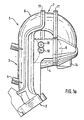
- the suction pipe 1 which is manufactured in the described embodiment using half-shell technology, has, as can be seen in FIG. 1a, the typical weld seams 11 which, for. B. connects the half-shell elements 6 and 7 with each other.
- the intake manifold 1 has a flange 2.
- the tubular elements 3 all open into the collecting space 4, which is halved by a separating element 5, shown schematically in FIG.
- the intake manifold 1 is z by means of the holder 9 in the engine compartment, not shown. B. a passenger car attached.
- the vacuum connections 10 attached to the suction pipe 1 the pressure conditions in the interior of the suction pipe are detected and z. B. used for control purposes.
- a connection to the exhaust gas recirculation 14 can also be seen on the intake manifold 1.
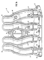
- the intake manifold 1 shown in Figure 1b has a motor-side flange 2, by means of which the intake manifold is attached to the engine block of the internal combustion engine.
- This engine-side flange 2 is by means of pipe elements 3, which in turn are composed of plastic half-shell elements 6 and 7 in this embodiment a collecting space 4 connected, which in turn communicates with the air filter, not shown.
- This collecting space 4 is restricted in its spatial spread by a separating element 5 and is lined by a housing wall 8.
- This separating element 5 acts as a propagation barrier for vibration modes which are dependent on the operating state of the internal combustion engine.
- the intake manifold 1 is fastened in the engine compartment by means of the holder 9.
- Injection valve receptacles 12 are provided on the intake manifold 1, into which the injection valves (not shown) are inserted, as well as fastening holes 13 via which the intake manifold is attached to the engine block.
- the entire suction pipe can also be made using the lost-melt technique, for this purpose but a certain complexity of the geometry is necessary, e.g. B. complicated inner contours, so that in the case of half-shell technology, several shells would be necessary for the Cost situation of the manufacturing process for the melting technology have advantages would.
- FIGS. 2a to 2e Different configurations of separating elements 5 are shown in FIGS. 2a to 2e see.
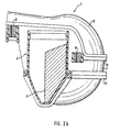
- FIG 2a the intake manifold 1 shown in Figure 1a is shown in section, the separating element 5 shown almost the entire cross-sectional area of the collecting space 4th includes. Also shown are the welds 11 which, for. B, the half-shell elements 6 and 7 connect.
- the intake manifold 1 is fastened in the engine compartment by means of the holder 9.
- the suction pipe 1 shown in Figure 1a is shown in section, the shown separating element 5 only about a quarter of the cross-sectional area of the Collection room 4 includes. Also shown are the welds 11 which, for. B. the Connecting half-shell elements 6 and 7 The suction pipe 1 is fastened by means of the holder 9 in Engine compartment.
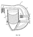
- the intake manifold 1 shown in Figure 1a is shown in section, the shown separating element 5 only half the cross-sectional area of the collecting space 4th includes. Also shown are the welds 11 which, for. B. the half-shell elements 6 and 7 connect.
- the intake manifold 1 is fastened in the engine compartment by means of the holder 9.
- the suction pipe 1 shown in Figure 1a is shown in section, the Separating element 5 shown approximately one third of the cross-sectional area of the collecting space 4th includes. Also shown are the welds 11 which, for. B. the half-shell elements 6 and 7 connect.
- the intake manifold 1 is fastened in the engine compartment by means of the holder 9.
- the suction pipe 1 shown in Figure 1a is shown in section, the Separating element 5 shown approximately two thirds of the cross-sectional area of the collecting space 4th includes. Also shown are the welds 11 which, for. B. the half-shell elements 6 and 7 connect.
- the intake manifold 1 is fastened in the engine compartment by means of the holder 9.
- the separating elements 5 shown in FIGS. 2b to 2e result in a reduction in the noise emission of the intake manifold, even if the cross section of the collecting space 4 is only reduced by 25 to 75%. On the one hand, this saves additional material, which corresponds to a reduction in weight, on the other hand, the air behind the separating element 5 acts like a spring on the air masses caused by the reduction in cross section caused by the separating element 5. Another alternative can be seen in the elastic mounting of separating element 5, which leads to a further reduction in the noise emission of the intake manifold.
- the arrangement of the separating element 5 in the collecting space 4 such that the distances from the housing wall 8 of the collecting space to the separating element 5 cannot be divided in whole numbers by the wavelength of the vibrations generated by the air flow or their multiples ensures a reduction in the noise emissions of the intake manifold 1.
- Another alternative which is not shown in the drawing, provides that the distance from the separating element 5 to the housing wall 8 of the collecting space 4 can be changed. By using either electromotive-controlled elements that move the partition 5 or the support of partition 5 by elements moved by vacuum, it is possible to set the ideal position of partition 5 to the housing wall 8 of the collecting space depending on the respective operating state of the internal combustion engine.
Landscapes
- Engineering & Computer Science (AREA)
- Chemical & Material Sciences (AREA)
- Combustion & Propulsion (AREA)
- Mechanical Engineering (AREA)
- General Engineering & Computer Science (AREA)
- Geometry (AREA)
- Physics & Mathematics (AREA)
- Characterised By The Charging Evacuation (AREA)
- Cooling, Air Intake And Gas Exhaust, And Fuel Tank Arrangements In Propulsion Units (AREA)
- Massaging Devices (AREA)
- Exhaust-Gas Circulating Devices (AREA)
- Valves And Accessory Devices For Braking Systems (AREA)
- Applications Or Details Of Rotary Compressors (AREA)
- Compressor (AREA)
- Endoscopes (AREA)
Applications Claiming Priority (3)
| Application Number | Priority Date | Filing Date | Title |
|---|---|---|---|
| DE19539078 | 1995-10-20 | ||
| DE19539078A DE19539078A1 (de) | 1995-10-20 | 1995-10-20 | Saugrohr |
| PCT/EP1996/002946 WO1997015755A1 (de) | 1995-10-20 | 1996-07-04 | Saugrohr |
Publications (2)
| Publication Number | Publication Date |
|---|---|
| EP0856102A1 EP0856102A1 (de) | 1998-08-05 |
| EP0856102B1 true EP0856102B1 (de) | 2001-10-31 |
Family
ID=7775339
Family Applications (1)
| Application Number | Title | Priority Date | Filing Date |
|---|---|---|---|
| EP96925658A Expired - Lifetime EP0856102B1 (de) | 1995-10-20 | 1996-07-04 | Saugrohr |
Country Status (11)
| Country | Link |
|---|---|
| US (1) | US6092499A (da) |
| EP (1) | EP0856102B1 (da) |
| JP (1) | JPH11513774A (da) |
| KR (1) | KR100393930B1 (da) |
| AT (1) | ATE208008T1 (da) |
| BR (1) | BR9611153A (da) |
| CA (1) | CA2235461A1 (da) |
| DE (2) | DE19539078A1 (da) |
| IN (1) | IN187196B (da) |
| WO (1) | WO1997015755A1 (da) |
| ZA (1) | ZA967335B (da) |
Families Citing this family (11)
| Publication number | Priority date | Publication date | Assignee | Title |
|---|---|---|---|---|
| JP3542725B2 (ja) * | 1998-09-30 | 2004-07-14 | 株式会社 マーレ テネックス | 自動車の吸気レゾネータ |
| DE19960223A1 (de) | 1999-07-15 | 2001-01-18 | Mann & Hummel Filter | Saugmodul für eine Brennkraftmaschine |
| DE19936470A1 (de) | 1999-08-03 | 2001-02-08 | Mann & Hummel Filter | Saugrohranlage |
| JP3585818B2 (ja) * | 2000-09-12 | 2004-11-04 | 本田技研工業株式会社 | 吸気マニホールド |
| DE10051116A1 (de) * | 2000-10-14 | 2002-04-25 | Mann & Hummel Filter | Saugrohr für eine Brennkraftmaschine mit mindestens zwei verschweißten Schalen |
| DE10126875A1 (de) * | 2001-06-01 | 2002-12-05 | Mann & Hummel Filter | Verschweißte Ansaugvorrichtung für eine Brennkraftmaschine |
| US6510833B1 (en) * | 2001-12-20 | 2003-01-28 | American Diesel & Gas, Inc. | Fuel saving combustion engine insulation method and system |
| US20030230272A1 (en) * | 2002-06-18 | 2003-12-18 | Siemens Vdo Automotive, Inc. | Valve actuation inlet noise control system |
| US7246593B2 (en) * | 2002-08-29 | 2007-07-24 | Siemens Canada Limited | Intake module assembly |
| DE10247913A1 (de) | 2002-10-14 | 2004-04-22 | Robert Bosch Gmbh | Plasmaanlage und Verfahren zum anisotropen Einätzen von Strukturen in ein Substrat |
| JP2019127881A (ja) * | 2018-01-24 | 2019-08-01 | トヨタ自動車株式会社 | 内燃機関のインテークマニホールド |
Family Cites Families (20)
| Publication number | Priority date | Publication date | Assignee | Title |
|---|---|---|---|---|
| DE2501305A1 (de) * | 1975-01-15 | 1976-07-22 | Bayerische Motoren Werke Ag | Luftansauganlage fuer brennkraftmaschinen |
| US4175504A (en) * | 1975-01-15 | 1979-11-27 | Bayerische Motoren Werke Ag | Air induction system for an internal combustion engine |
| JPS59103954A (ja) * | 1982-12-06 | 1984-06-15 | Honda Motor Co Ltd | 内燃機関の吸入装置 |
| JPS61138824A (ja) * | 1984-12-10 | 1986-06-26 | Toyota Motor Corp | 多気筒内燃機関の吸気管長可変式吸気装置 |
| JPH064028Y2 (ja) * | 1985-02-22 | 1994-02-02 | 三菱自動車工業株式会社 | 車両の吸気用サージタンク |
| US4803961A (en) * | 1985-11-19 | 1989-02-14 | Mazda Motor Corporation | Air suction devices for multicylinder engines |
| KR920001169B1 (ko) * | 1987-09-08 | 1992-02-06 | 마쓰다 가부시끼가이샤 | "v"형 엔진의 흡기장치 |
| DE4032380C2 (de) * | 1990-10-12 | 1995-01-05 | Daimler Benz Ag | Ansaugsystem für eine Brennkraftmaschine |
| SE9102125L (sv) * | 1991-07-08 | 1992-08-24 | Volvo Ab | Anordning vid foerbraenningsmotor med braensleinsprutning |
| DE4216255A1 (de) * | 1992-05-16 | 1993-11-18 | Mann & Hummel Filter | Ansaugrohr und Verfahren zu dessen Herstellung |
| FR2693252B1 (fr) * | 1992-07-01 | 1994-08-26 | Orbey Plastiques Ind | Dispositif pour adapter un élément chaud sur un corps creux en matière thermoplastique comportant au moins une arrivée de fluide froid, et corps creux comportant un tel dispositif. |
| JP3514496B2 (ja) * | 1993-11-08 | 2004-03-31 | 株式会社日立製作所 | 内燃機関の吸気装置 |
| US5704326A (en) * | 1992-12-10 | 1998-01-06 | Hitachi, Ltd. | Air induction system for internal-combustion engine |
| JPH06198918A (ja) * | 1992-12-28 | 1994-07-19 | Kanai Hiroyuki | ドットプリンタ用印字ワイヤ |
| US5377629A (en) * | 1993-10-20 | 1995-01-03 | Siemens Electric Limited | Adaptive manifold tuning |
| DE4402048A1 (de) * | 1994-01-25 | 1995-07-27 | Mann & Hummel Filter | Integriertes Ansaugsystem |
| US5636605A (en) * | 1994-06-22 | 1997-06-10 | Toyota Jidosha K.K. | Composite intake manifold for an internal combustion engine |
| DE4437677C2 (de) * | 1994-10-21 | 1997-12-04 | Mann & Hummel Filter | Verfahren zur Herstellung von Saugrohren und Saugrohr aus Kunststoff |
| DE19614313B4 (de) * | 1995-06-07 | 2006-08-10 | Volkswagen Ag | Saugrohranlage einer Brennkraftmaschine |
| DE19528047A1 (de) * | 1995-07-31 | 1997-02-06 | Bosch Gmbh Robert | Brennkraftmaschine mit einem daran befestigten Saugmodul bzw. Saugrohr und Verfahren zur Befestigung eines Saugmoduls bzw. Saugrohrs an einer Brennkraftmaschine |
-
1995
- 1995-10-20 DE DE19539078A patent/DE19539078A1/de active Pending
-
1996
- 1996-07-04 JP JP9516217A patent/JPH11513774A/ja active Pending
- 1996-07-04 EP EP96925658A patent/EP0856102B1/de not_active Expired - Lifetime
- 1996-07-04 BR BR9611153A patent/BR9611153A/pt not_active IP Right Cessation
- 1996-07-04 WO PCT/EP1996/002946 patent/WO1997015755A1/de not_active Ceased
- 1996-07-04 DE DE59608087T patent/DE59608087D1/de not_active Expired - Lifetime
- 1996-07-04 CA CA002235461A patent/CA2235461A1/en not_active Abandoned
- 1996-07-04 KR KR10-1998-0702737A patent/KR100393930B1/ko not_active Expired - Fee Related
- 1996-07-04 AT AT96925658T patent/ATE208008T1/de not_active IP Right Cessation
- 1996-07-04 US US09/051,742 patent/US6092499A/en not_active Expired - Lifetime
- 1996-07-16 IN IN374BO1996 patent/IN187196B/en unknown
- 1996-08-29 ZA ZA9607335A patent/ZA967335B/xx unknown
Also Published As
| Publication number | Publication date |
|---|---|
| KR19990064249A (ko) | 1999-07-26 |
| DE59608087D1 (de) | 2001-12-06 |
| CA2235461A1 (en) | 1997-05-01 |
| KR100393930B1 (ko) | 2003-11-17 |
| WO1997015755A1 (de) | 1997-05-01 |
| DE19539078A1 (de) | 1997-04-24 |
| BR9611153A (pt) | 1999-03-30 |
| JPH11513774A (ja) | 1999-11-24 |
| IN187196B (da) | 2002-02-23 |
| EP0856102A1 (de) | 1998-08-05 |
| US6092499A (en) | 2000-07-25 |
| ZA967335B (en) | 1998-02-27 |
| ATE208008T1 (de) | 2001-11-15 |
Similar Documents
| Publication | Publication Date | Title |
|---|---|---|
| DE102008005085B4 (de) | Verstellbare Helmholtz-Resonatoranordnung | |
| EP2399019B1 (de) | Wasserabscheider, insbesondere für kraftstoffzuführsysteme von brennkraftmaschinen in kraftfahrzeugen | |
| DE69916211T3 (de) | Zweitaktmotor mit geschichteter Spülung | |
| EP0990093B1 (de) | Ansaugsystem, insbesondere zur verwendung als ansaugkanal einer verbrennungskraftmaschine | |
| DE4006438C2 (de) | Abgasanlage für einen Viertakt-Vierzylindermotor | |
| DE10036241A1 (de) | Integriertes Luftansaugmodul für Benzinmotoren | |
| DE102008002314A1 (de) | Schallqualitätssteuerungsgerät für eine Brennkraftmaschine | |
| EP1306829B1 (de) | Vorrichtung zur Übertragung von Brennkraftmaschinengeräuschen | |
| DE112004002158T5 (de) | Ansaugvorrichtung einer Brennkraftmaschine | |
| EP2226107A1 (de) | Wasserabscheider insbesondere für Kraftstoffzuführsysteme von Brennkraftmaschinen in Kraftfahrzeugen | |
| DE102009056048A1 (de) | Bauliches Ölschwallblech für Motordeckel | |
| EP3652419A1 (de) | Zylinderkopfölabscheider für einen verbrennungsmotor (strömungsgeführter ölabscheider) | |
| DE10042012A1 (de) | Vorrichtung zur Geräuschgestaltung bei einem Kraftfahrzeug | |
| DE102010043267A1 (de) | Schalldämpfer für ein Lufteinlasssystem eines Verbrennungsmotors | |
| DE102017210921A1 (de) | Fahrzeugluftkanal zum Reduzieren von Einlassgeräuschen | |
| EP0856102A1 (de) | Saugrohr | |
| DE102008031118A1 (de) | Motorrad-Luftkasten mit einem Helmholtz-Resonator | |
| DE10243881A1 (de) | Schalldämpfer zur Verringerung von Luftgeräuschen und Verfahren zur Herstellung desselben | |
| DE19650806A1 (de) | Luftführungsanlage | |
| DE102020127763A1 (de) | Luftfiltervorrichtung in einem luftansaugsystem für einen motor und verfahren zur verwendung der vorrichtung | |
| EP1024258A2 (de) | Luftsauganlagen | |
| WO1999002828A1 (de) | Rohrsystem, insbesondere saugrohr einer brennkraftmaschine | |
| DE102013207586A1 (de) | Luftfilter mit integriertem Resonator | |
| EP0832352B1 (de) | Rohrmodul | |
| DE69602271T3 (de) | Ansaugkrümmer für brennkraftmaschine |
Legal Events
| Date | Code | Title | Description |
|---|---|---|---|
| PUAI | Public reference made under article 153(3) epc to a published international application that has entered the european phase |
Free format text: ORIGINAL CODE: 0009012 |
|
| 17P | Request for examination filed |
Effective date: 19980316 |
|
| AK | Designated contracting states |
Kind code of ref document: A1 Designated state(s): AT BE CH DE ES FR GB IT LI NL SE |
|
| 17Q | First examination report despatched |
Effective date: 20000717 |
|
| GRAG | Despatch of communication of intention to grant |
Free format text: ORIGINAL CODE: EPIDOS AGRA |
|
| GRAH | Despatch of communication of intention to grant a patent |
Free format text: ORIGINAL CODE: EPIDOS IGRA |
|
| RAP1 | Party data changed (applicant data changed or rights of an application transferred) |
Owner name: FILTERWERK MANN+HUMMEL GMBH |
|
| GRAH | Despatch of communication of intention to grant a patent |
Free format text: ORIGINAL CODE: EPIDOS IGRA |
|
| GRAA | (expected) grant |
Free format text: ORIGINAL CODE: 0009210 |
|
| AK | Designated contracting states |
Kind code of ref document: B1 Designated state(s): AT BE CH DE ES FR GB IT LI NL SE |
|
| PG25 | Lapsed in a contracting state [announced via postgrant information from national office to epo] |
Ref country code: NL Free format text: LAPSE BECAUSE OF FAILURE TO SUBMIT A TRANSLATION OF THE DESCRIPTION OR TO PAY THE FEE WITHIN THE PRESCRIBED TIME-LIMIT Effective date: 20011031 Ref country code: IT Free format text: LAPSE BECAUSE OF FAILURE TO SUBMIT A TRANSLATION OF THE DESCRIPTION OR TO PAY THE FEE WITHIN THE PRE;WARNING: LAPSES OF ITALIAN PATENTS WITH EFFECTIVE DATE BEFORE 2007 MAY HAVE OCCURRED AT ANY TIME BEFORE 2007. THE CORRECT EFFECTIVE DATE MAY BE DIFFERENT FROM THE ONE RECORDED.SCRIBED TIME-LIMIT Effective date: 20011031 Ref country code: GB Free format text: LAPSE BECAUSE OF FAILURE TO SUBMIT A TRANSLATION OF THE DESCRIPTION OR TO PAY THE FEE WITHIN THE PRESCRIBED TIME-LIMIT Effective date: 20011031 Ref country code: FR Free format text: LAPSE BECAUSE OF FAILURE TO SUBMIT A TRANSLATION OF THE DESCRIPTION OR TO PAY THE FEE WITHIN THE PRESCRIBED TIME-LIMIT Effective date: 20011031 |
|
| REF | Corresponds to: |
Ref document number: 208008 Country of ref document: AT Date of ref document: 20011115 Kind code of ref document: T |
|
| REG | Reference to a national code |
Ref country code: CH Ref legal event code: EP |
|
| REF | Corresponds to: |
Ref document number: 59608087 Country of ref document: DE Date of ref document: 20011206 |
|
| PG25 | Lapsed in a contracting state [announced via postgrant information from national office to epo] |
Ref country code: SE Free format text: LAPSE BECAUSE OF FAILURE TO SUBMIT A TRANSLATION OF THE DESCRIPTION OR TO PAY THE FEE WITHIN THE PRESCRIBED TIME-LIMIT Effective date: 20020131 |
|
| NLV1 | Nl: lapsed or annulled due to failure to fulfill the requirements of art. 29p and 29m of the patents act | ||
| PG25 | Lapsed in a contracting state [announced via postgrant information from national office to epo] |
Ref country code: ES Free format text: LAPSE BECAUSE OF FAILURE TO SUBMIT A TRANSLATION OF THE DESCRIPTION OR TO PAY THE FEE WITHIN THE PRESCRIBED TIME-LIMIT Effective date: 20020430 |
|
| GBV | Gb: ep patent (uk) treated as always having been void in accordance with gb section 77(7)/1977 [no translation filed] |
Effective date: 20011031 |
|
| PG25 | Lapsed in a contracting state [announced via postgrant information from national office to epo] |
Ref country code: AT Free format text: LAPSE BECAUSE OF NON-PAYMENT OF DUE FEES Effective date: 20020704 |
|
| PG25 | Lapsed in a contracting state [announced via postgrant information from national office to epo] |
Ref country code: LI Free format text: LAPSE BECAUSE OF NON-PAYMENT OF DUE FEES Effective date: 20020731 Ref country code: CH Free format text: LAPSE BECAUSE OF NON-PAYMENT OF DUE FEES Effective date: 20020731 Ref country code: BE Free format text: LAPSE BECAUSE OF NON-PAYMENT OF DUE FEES Effective date: 20020731 |
|
| PLBE | No opposition filed within time limit |
Free format text: ORIGINAL CODE: 0009261 |
|
| STAA | Information on the status of an ep patent application or granted ep patent |
Free format text: STATUS: NO OPPOSITION FILED WITHIN TIME LIMIT |
|
| 26N | No opposition filed | ||
| BERE | Be: lapsed |
Owner name: FILTERWERK *MANN + HUMMEL G.M.B.H. Effective date: 20020731 |
|
| REG | Reference to a national code |
Ref country code: CH Ref legal event code: PL |
|
| PGFP | Annual fee paid to national office [announced via postgrant information from national office to epo] |
Ref country code: DE Payment date: 20110722 Year of fee payment: 16 |
|
| PG25 | Lapsed in a contracting state [announced via postgrant information from national office to epo] |
Ref country code: DE Free format text: LAPSE BECAUSE OF NON-PAYMENT OF DUE FEES Effective date: 20130201 |
|
| REG | Reference to a national code |
Ref country code: DE Ref legal event code: R119 Ref document number: 59608087 Country of ref document: DE Effective date: 20130201 |