EP0855208B1 - Verfahren zur Herstellung eines Filterelements und Giessform dafür - Google Patents
Verfahren zur Herstellung eines Filterelements und Giessform dafür Download PDFInfo
- Publication number
- EP0855208B1 EP0855208B1 EP97120654A EP97120654A EP0855208B1 EP 0855208 B1 EP0855208 B1 EP 0855208B1 EP 97120654 A EP97120654 A EP 97120654A EP 97120654 A EP97120654 A EP 97120654A EP 0855208 B1 EP0855208 B1 EP 0855208B1
- Authority
- EP
- European Patent Office
- Prior art keywords
- molding die
- die member
- suction
- outer peripheral
- peripheral surface
- Prior art date
- Legal status (The legal status is an assumption and is not a legal conclusion. Google has not performed a legal analysis and makes no representation as to the accuracy of the status listed.)
- Expired - Lifetime
Links
- 238000000465 moulding Methods 0.000 title claims description 58
- 238000000034 method Methods 0.000 title claims description 20
- 238000004519 manufacturing process Methods 0.000 title claims description 18
- 239000002002 slurry Substances 0.000 claims description 50
- 230000002093 peripheral effect Effects 0.000 claims description 47
- 239000011347 resin Substances 0.000 claims description 28
- 229920005989 resin Polymers 0.000 claims description 28
- XLYOFNOQVPJJNP-UHFFFAOYSA-N water Substances O XLYOFNOQVPJJNP-UHFFFAOYSA-N 0.000 claims description 23
- 239000000463 material Substances 0.000 claims description 20
- 238000001035 drying Methods 0.000 claims description 5
- 150000001768 cations Chemical class 0.000 claims description 2
- 239000011435 rock Substances 0.000 claims description 2
- 230000000717 retained effect Effects 0.000 claims 3
- 230000001012 protector Effects 0.000 description 83
- 239000000835 fiber Substances 0.000 description 48
- 239000011230 binding agent Substances 0.000 description 19
- 239000002904 solvent Substances 0.000 description 8
- 239000003921 oil Substances 0.000 description 6
- NJPPVKZQTLUDBO-UHFFFAOYSA-N novaluron Chemical compound C1=C(Cl)C(OC(F)(F)C(OC(F)(F)F)F)=CC=C1NC(=O)NC(=O)C1=C(F)C=CC=C1F NJPPVKZQTLUDBO-UHFFFAOYSA-N 0.000 description 4
- WSFSSNUMVMOOMR-UHFFFAOYSA-N Formaldehyde Chemical compound O=C WSFSSNUMVMOOMR-UHFFFAOYSA-N 0.000 description 3
- OKKJLVBELUTLKV-UHFFFAOYSA-N Methanol Chemical compound OC OKKJLVBELUTLKV-UHFFFAOYSA-N 0.000 description 3
- 238000005470 impregnation Methods 0.000 description 3
- 125000006850 spacer group Chemical group 0.000 description 3
- 238000001914 filtration Methods 0.000 description 2
- 238000012423 maintenance Methods 0.000 description 2
- 230000004048 modification Effects 0.000 description 2
- 238000012986 modification Methods 0.000 description 2
- 239000003960 organic solvent Substances 0.000 description 2
- 239000005011 phenolic resin Substances 0.000 description 2
- 239000012779 reinforcing material Substances 0.000 description 2
- 241000723353 Chrysanthemum Species 0.000 description 1
- 235000005633 Chrysanthemum balsamita Nutrition 0.000 description 1
- 208000005156 Dehydration Diseases 0.000 description 1
- ISWSIDIOOBJBQZ-UHFFFAOYSA-N Phenol Chemical compound OC1=CC=CC=C1 ISWSIDIOOBJBQZ-UHFFFAOYSA-N 0.000 description 1
- -1 acryl Chemical group 0.000 description 1
- 230000015572 biosynthetic process Effects 0.000 description 1
- 238000002485 combustion reaction Methods 0.000 description 1
- 238000005260 corrosion Methods 0.000 description 1
- 230000007797 corrosion Effects 0.000 description 1
- 230000018044 dehydration Effects 0.000 description 1
- 238000006297 dehydration reaction Methods 0.000 description 1
- 230000001419 dependent effect Effects 0.000 description 1
- 238000011161 development Methods 0.000 description 1
- 230000018109 developmental process Effects 0.000 description 1
- 239000006185 dispersion Substances 0.000 description 1
- 239000000839 emulsion Substances 0.000 description 1
- 230000005484 gravity Effects 0.000 description 1
- 239000010687 lubricating oil Substances 0.000 description 1
- 230000007246 mechanism Effects 0.000 description 1
- 238000002156 mixing Methods 0.000 description 1
- 239000000203 mixture Substances 0.000 description 1
- 239000002245 particle Substances 0.000 description 1
- 229920000728 polyester Polymers 0.000 description 1
- 238000003825 pressing Methods 0.000 description 1
- 230000008569 process Effects 0.000 description 1
- 230000009467 reduction Effects 0.000 description 1
- 238000001179 sorption measurement Methods 0.000 description 1
- 229910001220 stainless steel Inorganic materials 0.000 description 1
- 239000010935 stainless steel Substances 0.000 description 1
Images


Classifications
-
- D—TEXTILES; PAPER
- D21—PAPER-MAKING; PRODUCTION OF CELLULOSE
- D21J—FIBREBOARD; MANUFACTURE OF ARTICLES FROM CELLULOSIC FIBROUS SUSPENSIONS OR FROM PAPIER-MACHE
- D21J7/00—Manufacture of hollow articles from fibre suspensions or papier-mâché by deposition of fibres in or on a wire-net mould
-
- B—PERFORMING OPERATIONS; TRANSPORTING
- B01—PHYSICAL OR CHEMICAL PROCESSES OR APPARATUS IN GENERAL
- B01D—SEPARATION
- B01D29/00—Filters with filtering elements stationary during filtration, e.g. pressure or suction filters, not covered by groups B01D24/00 - B01D27/00; Filtering elements therefor
- B01D29/11—Filters with filtering elements stationary during filtration, e.g. pressure or suction filters, not covered by groups B01D24/00 - B01D27/00; Filtering elements therefor with bag, cage, hose, tube, sleeve or like filtering elements
- B01D29/111—Making filtering elements
-
- B—PERFORMING OPERATIONS; TRANSPORTING
- B01—PHYSICAL OR CHEMICAL PROCESSES OR APPARATUS IN GENERAL
- B01D—SEPARATION
- B01D29/00—Filters with filtering elements stationary during filtration, e.g. pressure or suction filters, not covered by groups B01D24/00 - B01D27/00; Filtering elements therefor
- B01D29/11—Filters with filtering elements stationary during filtration, e.g. pressure or suction filters, not covered by groups B01D24/00 - B01D27/00; Filtering elements therefor with bag, cage, hose, tube, sleeve or like filtering elements
- B01D29/13—Supported filter elements
- B01D29/15—Supported filter elements arranged for inward flow filtration
- B01D29/21—Supported filter elements arranged for inward flow filtration with corrugated, folded or wound sheets
-
- B—PERFORMING OPERATIONS; TRANSPORTING
- B01—PHYSICAL OR CHEMICAL PROCESSES OR APPARATUS IN GENERAL
- B01D—SEPARATION
- B01D39/00—Filtering material for liquid or gaseous fluids
- B01D39/14—Other self-supporting filtering material ; Other filtering material
- B01D39/16—Other self-supporting filtering material ; Other filtering material of organic material, e.g. synthetic fibres
- B01D39/1607—Other self-supporting filtering material ; Other filtering material of organic material, e.g. synthetic fibres the material being fibrous
- B01D39/1623—Other self-supporting filtering material ; Other filtering material of organic material, e.g. synthetic fibres the material being fibrous of synthetic origin
- B01D39/163—Other self-supporting filtering material ; Other filtering material of organic material, e.g. synthetic fibres the material being fibrous of synthetic origin sintered or bonded
-
- B—PERFORMING OPERATIONS; TRANSPORTING
- B01—PHYSICAL OR CHEMICAL PROCESSES OR APPARATUS IN GENERAL
- B01D—SEPARATION
- B01D2101/00—Types of filters having loose filtering material
- B01D2101/005—Types of filters having loose filtering material with a binder between the individual particles or fibres
-
- B—PERFORMING OPERATIONS; TRANSPORTING
- B01—PHYSICAL OR CHEMICAL PROCESSES OR APPARATUS IN GENERAL
- B01D—SEPARATION
- B01D2239/00—Aspects relating to filtering material for liquid or gaseous fluids
- B01D2239/10—Filtering material manufacturing
Definitions
- the present invention relates to a method for manufacturing a filter element having a number of concavities and convexities on an outer peripheral surface thereof by suction molding, and a molding die for use therein.
- the contouring jig 52 has a plurality of leg portions 52a disposed in such a way as to oppose the concavities of the protector 51 and gaps permitting the passage of the fibers therethrough are formed between these leg portions 52a.
- the present invention has an object to provide a method for manufacturing a filter element which has less non-walled portions.
- the present invention has another object to provide a die suitable for the manufacturing method.
- a second molding die member is disposed at a second position more remote from the outer peripheral surface of the first molding die member than the first position.
- a filter element 100 which is cylindrical in configuration as illustrated in Fig. 3 has on an outer peripheral surface thereof a number of axially extending fin-like portions 101 (composed of concavities and convexities) and may be used as an oil filter for filtering a lubricating oil of, for example, an internal combustion engine.
- central holes 102 are open, respectively, and the central hole 102 at one end thereof serves as a sucking-out port which is connected to a housing (not illustrated) when the filter element 100 is accommodated within the housing as an oil filter while, on the other hand, the central hole 102 at the other end thereof is closed by a relief valve (not illustrated).
- a relief valve not illustrated
- the above-described filter element 100 is formed using a suction molding apparatus illustrated in Fig. 4.
- the suction apparatus comprises a water tank 2 having received therein a water slurry 1 containing fibers used as filter material, an agitator 3 for agitating the slurry 1 within this water tank 2, a suction jig 4 (molding die) for sucking the slurry 1 within the water tank 2 and thereby forming a molded body 16, and a suction pump 7 for sucking the slurry 1 through a suction hose 5 connected to this suction jig 4 and returning the slurry 1 into the water tank 2 through a discharge hose 6.
- the fibers used as filter material of an oil filter there are polyester useful for obtaining the oilproof strength, acryl useful for obtaining the filtering performance, pulp enabling the reduction in cost, etc.
- the suction jig 4 comprises a circular base portion 9 having a connection pipe 8, a hollow cylindrical suction core 10 assembled to the base portion 9, a protector 11 mounted onto an outer periphery of the suction core 10 and serving as a first molding die member and a contouring jig 12 used in combination with the protector 11 and serving as a second molding die member.
- connection pipe 8 there is connected at an open end thereof a suction hose 5 via a joint 13.
- the joint 13 is fixed to the connection pipe 8 by means of a stopper 14, provided, however, that the joint 13 is connected so that the connection pipe 8 and the suction pipe 5 are held relatively rotatably.
- the suction core 10 has a number of suction openings 10a formed substantially uniformly over an entire region thereof. It is to be noted that it may be arranged that the porosity of the suction openings 10a may increase by the number of the suction openings 10a being increased in the axial direction of the suction core 10 from the base portion 9 toward a side opposite thereto (from the downside to the upside in Figs. 1 and 2).
- a forward or top end of the suction core 10 is closed and has formed therein a hole into which a jig fixing bolt 15 is screwed.
- a jig fixing bolt 15 is screwed.
- the protector 11 which may be made of stainless steel having excellent corrosion resistance and is shaped like a hollow cylindrical star in cross section and opened at its both ends.
- the protector 11 has a number of suction openings 11a in a wall surface thereof. It is to be noted that the size of the suction opening 11a is set at a value enabling fibers to be filtered from the slurry 1. Also, the suction openings 11a are formed in the wall surface of the protector 11 with such a density as to cause no undesirable pressure loss during the suction molding time period. It is to be noted that the protector 11 has prescribed rigidities in its axial and radial directions.
- the protector 11 is a member which defines an inner peripheral configuration of the filter element 100, i.e., which in the case of an oil filter defines the configuration on a clean side. It is substantially shaped like a hollow cylinder.
- the protector 11 has formed on an outer surface thereof a plurality of convexities 11b1 extending along the longitudinal axis thereof and in the radially outward direction thereof and a plurality of substantially V-shaped grooves (concavities or recesses) 11b2 defined between the convexities 11b1.
- the outer surface of the protector 11 has the fin-like portions 11b.
- a circular, columnar central space 11c enabling the suction core 10 to be received therein.
- a plurality of triangular, columnar fin-like spaces 11d are defined by the fin-like portions 11b in such a way as to radially spread from this central space 11c.
- the central hole 102 having a substantially circular contour and fin portion openings corresponding to the fin-like portions 11b. These fin portion openings are gaps which enable fibers to be filtered from the slurry 1.
- the protector 11 may be worked so as to make the gaps of the fin portion openings narrow or close these gaps, in order to close the central hole 102 by contact between the protector 11 and another member in a succeeding step it is important that the fibers be accumulated over an entire outside circumference of the central hole 102 and that, therefore, it be arranged that the fibers are accumulated also on the openings of the fin-like portions 11b. Also, by forming the central holes 102 in both end surfaces of the protector 11, it is possible to use one of the two as the outlet of an oil filter and mount a relief valve thereof on the other of the two.
- a pedestal 9a composed of a spacer portion 9b which when the protector 11 is been assembled to the suction core 10 abuts against a lower end surface of the protector 11 to thereby ensure the maintenance of a prescribed gap between the lower end surface of the protector 11 and the base portion 9 and a stopper portion 9c which engages the fin-like portions 11b of the protector 11 to thereby prevent the rotation of the protector 11.
- the surface of the base portion 9 on the side of the protector 11 constitutes a part of the contouring jig 12 for defining the outer configuration of the molded body 16 prepared by the fibers being accumulated in the above-mentioned gap.
- the contouring jig 12 is a member for defining the outer configuration of the filter element 100, the configuration of the oil filter on the dusty side in this embodiment.
- the contouring jig 12 is equipped with a retaining portion 12a assembled to the protector 11 and a plurality of leg portions 12b rotatably mounted on the retaining portion 12a.
- a surface of the retaining portion 12a which when the contouring jig 12 is assembled to the protector 11 is on the side of the protector 11 has thereon a pedestal 12c corresponding to the pedestal 9a of the base portion 9.
- the pedestal 12c has a spacer portion 12d which when the contouring jig 12 is assembled to the protector 11 abuts against an upper end surface of the protector 11 to thereby ensure the maintenance of a prescribed gap between the upper end surface of the protector 11 and the retaining portion 12a and a stopper portion 12e which engages the fin-like portions 11b of the protector 11 to thereby prevent the rotation of the protector 11.
- the surface of the retaining portion 12a on the side of the protector 11 has a smooth surface and defines the outer configuration of the fibers accumulated in the gap between the protector 11 and the retaining portion 12a. That is, the configuration of the top end surface of the filter element 100 is defined by the retaining portion 12a.
- a plurality of substantially triangular, columnar leg portions 12b are mounted at one bottom end surface of the retaining portion 12a and are arranged to rock or swing in a radial direction by driving means (e.g., an electric motor, link mechanism, etc.) about the end portions thereof mounted to the retaining portion 12a. It is arranged that by being rocked, each leg portion 12b can be moved between a first position (Fig. 2) spaced by a prescribed uniform distance from the outer peripheral surface of the protector 11 and a second position (Fig. 1) more remote from this outer peripheral surface thereof than the first position.
- driving means e.g., an electric motor, link mechanism, etc.
- leg portion 12b when disposed at the first position, the leg portion 12b is mounted to the retaining portion 12a so that a forward or radially inside end portion 12b1 thereof may be located at the position of its opposing the groove portion 11b2 of the protector 11.
- the fibers which are previously finely severed by a mixer (not illustrated) or the like are introduced into the water tank 2 jointly with binder fibers (thermofusible fibers) used as reinforcing material of the filter element 100. Then, the resulting water slurry 1 is agitated by the agitator 3 for dispersion of the contents thereof to thereby make the fiber concentration thereof uniform.
- the suction jig 4 is immersed in the slurry 1 and then the suction pump 7 is operated, whereby the suction molding is performed.
- This suction molding step is executed by, while rotating the suction jig 4, adjusting the amount of the slurry sucked in by the suction pump 7.
- the slurry 1 in the water tank 2 flows through the suction jig 4 - suction hose 5 - suction pump 7 - discharge hose 6 and again flows back to the water tank 2, whereby the slurry 1 circulates.
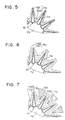
- the fibers contained in the slurry 1 attach onto the outer peripheral surface of the protector 11 without passing through the suction openings 11a. Further, the fibers contained in the slurry 1 are sequentially accumulated on the fibers having attached onto the outer peripheral surface of the protector 11 as shown in Figs. 5 and 6.
- the leg portion 12b of the contouring jig 12 is disposed at the second position.
- the bottom ends of the leg portions 12b are in an open state (second position) of their having been moved in the direction of their radially going away from the protector 11, i.e., in a state of their having been opened as if an umbrella has been opened. Therefore, the slurry 1 can be caused to flow into a deep position of the groove portion 11b2 of the protector 11 with no fiber contained in the slurry 1 being caught between the leg portions 12b and the protector 11. For this reason, the fibers can be accumulated without causing the occurrence of a non-walled portion in the groove portion 11b2 of the protector 11.
- the forward end portion 12b1 moved radially inward to be disposed vertically in the groove portions 11b2 of the protector 11, with the result that the leg portions 12b are brought to a state of their having been disposed at a position (first position) spaced by the prescribed uniform distance from the outer peripheral surface of the protector 11, i.e., to a state of their having been closed as if an umbrella has been closed as shown in Fig. 7.
- the slurry 1 flows into the protector 11 and the leg portions 12b, whereby the fibers contained in the slurry 1 are further accumulated on the outer peripheral surface of the protector 11.
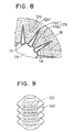
- the hollow, cylindrical molded body 16 having a number of fin-like portions 101 on an outer peripheral surface thereof and star shaped in cross section with a generally uniform wall thickness as shown in Fig. 8. It is to be noted that the fibers are accumulated on both the top and bottom end surfaces of the protector 11 as well as between the protector 11 and the leg portions 12b, whereby the fibers are accumulated on the entire outerperiphery of the protector 11.
- the molded body 16 is taken out from the suction jig 4 together with the protector 11 and is subjected to dehydration treatment.
- the binder resin e.g., thermohardening resin such as water dispersible phenol resin
- the binder resin which has been dispersed in water and thereby made colloidal and has had positive charges imparted thereto is impregnated into the molded body 16, after which the resulting molded body is heated at a prescribed temperature and thereby dried to harden the binder resin.
- the water dispersible phenol resin has the following characteristics. outlook white or light brown emulsion nonvolatility 39 - 41 % viscosity 300 - 800 cps/25°C pH 4.7 - 5.1 specific gravity 1.10 - 1.14 free formaldehyde less than 2.5 % free phenol less than 2.5 % dispersibility stably dispersible in water particle charge cation
- the filter element 100 such as that illustrated in Fig. 3 which has on the outer peripheral surface thereof a number of fin-like portions 101.
- the leg portions 12b of the contouring jig 12 are in a state of their being opened and are disposed at the position (second position) spaced away from the protector 11. Therefore, the slurry 1 can be caused to flow into a deep or bottom position of the groove portion 11b2 of the protector 11 with no fiber contained in the slurry 1 sucked by the suction pump 7 being caught between the leg portions 12b and the protector 11. For this reason, the fibers can be accumulated on the outer peripheral surface of the protector 11 without causing the occurrence of a non-walled portion.
- the leg portions 12b are moved toward the protector 11 and thereby are disposed at the first position.
- the slurry 1 is caused to flow into between the protector 11 and the contouring jig 12.
- the binder resin impregnated into the molded body 16 after this molded body has been formed there is used water dispersible thermohardening resin which is stably dispersed in water.
- the solvent for the slurry 1 and the solvent for the binder resin can be made common to each other. Accordingly, it is possible to perform the resin impregnation in succession to the forming of the molded body 16 by the suction molding operation without drying the molded body once thereafter. Therefore, it is possible to omit the step of, after forming the molded body 16, drying this molded body once, which step is needed when using, for example, organic solvent such as methanol as the solvent for the binder resin. Thus, it is possible to simplify the manufacturing process.
- the binder resin is impregnated into the molded body 16 and thereafter the resulting molded body 16 is dried, the solvent of the binder resin is evaporated from the surface of the filter element 100 and so is moved to the surface thereof.
- positive charges are imparted to the binder resin impregnated into the molded body 16, it is possible to increase the adsorption force between the binder resin and the fibers having negative charges.
- the leg portions 12b are moved toward the protector 11 whereby the suction of the slurry 1 is subsequently performed.
- the formation of the molded body may be performed with the use of a method which comprises preparing beforehand a slurry containing a prescribed amount of fibers and performing the suction molding operation, moving the leg portions toward the protector side, and causing the suction of a slurry containing the remaining amount of fibers which has been prepared in a separate water tank.
- the configuration of the outer peripheral surface of the molded body 16 is defined using the contouring jig 12 whose leg portions 12b are rockably or swingably mounted at one end on the retaining portion 12a, there may be used a contouring jig whose plural leg portions disposed so as to surround the outer peripheral surface of the protector are moved toward the protector side in the radial direction of the molded body with both of its top and bottom ends moving equally.
- the filter element 100 is manufactured to have a plurality of the fin-like portions 101 formed in the axial direction thereof, the method may be applied to other filter elements having a plurality of concavities and convexities on the outer peripheral surface thereof.
- a filter element (molded body) 160 having a plurality of fin-like portions formed in a direction substantially perpendicular to the axial direction thereof by the use of a bellows-shaped protector 120 such as that illustrated in Fig. 9.
- a filter element (molded body) 170 having a plurality of concavities and convexities formed on the outer peripheral surface thereof by the use of a petal-shaped protector 130 called "a daisy type" such as that illustrated in Fig. 10.
- a spherical filter element (molded body) having a plurality of concavities and convexities formed on the outer peripheral surface thereof by the use of not a cylindrical protector but a spherical protector having a plurality of concavities and convexities formed on the outer peripheral surface thereof.
- the slurry 1 is suction molded to thereby form the molded body 16 and thereafter the binder resin dispersed in water is impregnated into this molded body 16
- the water dispersible resin as the binder resin there may be used as a slurry suction molded by the suction jig a slurry obtained by blending the binder resin thereinto together with the filter material and reinforcing material and preparing the resulting mixture.
- thermohardening resin having an organic solvent property.
- the solvent of the slurry and the solvent of the binder resin differ from each other, it is necessary to dry the molded body before the impregnation of the binder resin into this molded body.
- the filter element 100 has the fin-like portions 101 whose concavities and convexities are substantially V-shaped in cross section and the molding die for use therein
- the cross-sectional configuration of the concavities and convexities formed on the outer peripheral surface of the filter element (molded body) manufactured by the above-described manufacturing method and molding die may be one having a flat bottom surface.
- the filter element has concavities each of which is shaped like a groove
- the present invention is not limited to the method for manufacturing the filter element whose concavities are each shaped like a groove and the molding die for use therein.
- the manufacturing method of the filter element is one directed to manufacturing the filter element having a number of concavities and convexities formed on the outer peripheral surface thereof, the present invention can be applied thereto and the cross-sectional configuration and the configuration of a plurality of concavities and convexities formed on the outer peripheral surface of the molded body and filter element are not limitative in particular.
Claims (14)
- Verfahren zur Herstellung eines Filterelements, das eine Anzahl von Höhlungen und Wölbungen aufweist, wobei das Verfahren aus den Stufen besteht:wobei die Veranlassungsstufe veranlasst, dass während einer Zeitdauer vom Beginn der Ansaugung der Schlämmung (1) zu einem Zeitpunkt, wenn der Filterwerkstoff mit vorgeschriebener Stärke an der äußeren Umfangsfläche des ersten Modellformteils (11) angesammelt ist, wobei der zweite Modellformteil (12) in einer zweiten Position ist, die weiter entfernt ist von der äußeren Umgebungsfläche des ersten Modellformteils (11) als die erste Position, um damit zu verursachen, dass sich der Filterwerkstoff in vorgeschriebener Stärke an der äußeren Umfangsfläche des ersten Modellformteils (11) ansammelt, und danach bewegt sich das zweite Modellformteil (12) aus der zweiten Position in die erste Position und veranlasst weiter, dass der Filterwerkstoff zwischen dem ersten und dem zweiten Modellformteil (11, 12) angesammelt wird, um dadurch die Anzahl an Höhlungen und Wölbungen auf der äußeren Umfangsfläche des gegossenen Körpers (100, 160, 170) zu bilden.Ansaugen einer Wasseraufschlämmung (1), die Filterwerkstoff enthält, durch ein erstes Modellformteil (11, 120), das eine Anzahl von darin eingeformten Ansaugöffnungen (11a) aufweist, und eine Vielzahl von Höhlungen (11b2) und Wölbungen (11b1) aufweist, ausgebildet in dessen äußerer Umfangsfläche;Veranlassen des Filterwerkstoffes sich zwischen dem ersten Modellformteil (11, 120) und einem zweiten Modellformteil (12), vorgesehen den Aushöhlungen (11b2) des ersten Modellformteils (11, 120) gegenüber zu sein, und vorgesehen in einer ersten Position, die durch einen vorgeschriebenen Abstand von der äußeren Umfangsfläche des ersten Modellformteils (11, 120) beabstandet ist; undBilden eines gegossenen Körpers (100, 160, 170) durch die Veranlassungsstufe, wobei der gegossene Körper (100, 160, 170) eine Anzahl an Höhlungen und Wölbungen an dessen äußerer Umfangsfläche aufweist,
- Verfahren gemäß Anspruch 1, wobei nach einer vorgeschriebenen Zeitdauer, die vom Beginn des Ansaugens der Schlämmung (1) an bis die vorgeschriebene Stärke erreicht ist dauert, das zweite Modellformteil (12) von der zweiten Position (Fig. 1) in die erste Position (Fig. 2) bewegt wird.
- Verfahren gemäß Anspruch 1, wobei die vorgeschriebene Stärke 10 bis 70% des gesamten Filterwerkstoffes entspricht, der endgültig anzusammeln ist.
- Verfahren gemäß Anspruch 3, wobei die vorgeschriebene Stärke 20 bis 40% des gesamten Filterwerkstoffes entspricht, der endgültig anzusammeln ist.
- Verfahren gemäß einem der Ansprüche von 1 bis 4, das außerdem aus den Stufen besteht:Imprägnieren des gegossenen Körpers mit einem warmhärtenden, in Wasser gelösten Kunstharz; undTrocknen des imprägnierten, gegossenen Körpers.
- Verfahren gemäß einem der Ansprüche von 1 bis 4, das außerdem aus den Stufen besteht:Hinzufügen eines warmhärtenden, in Wasser gelösten Kunstharz zur Wasseraufschlämmung (1), um dadurch den gegossenen Körper (100, 160, 170) mit warmhärtendem Kunstharz; undTrocknen und Härten des imprägnierten gegossenen Körpers.
- Verfahren gemäß Anspruch 5 oder 6, wobei dem warmhärtenden Kunstharz Kationen beigegeben sind.
- Verfahren gemäß einem der Ansprüche von 1 bis 7, wobei das zweite Modellformteil (12) ein Halteteil (12a) und eine Vielzahl von beweglichen Teilen (12b) aufweist, die durch das Halteteil (12) beweglich gehalten sind, so dass die beweglichen Teile (12b) aus der zweiten Position (Fig. 1) in die erste Position (Fig. 2) bewegt sind.
- Verfahren gemäß Anspruch 8, wobei die beweglichen Teile (12b) in Fußform ausgebildet, sich in Längsrichtung vom Halteteil (12a) aus erstrecken.
- Verfahren gemäß Anspruch 9, wobei die beweglichen Teile (12b) bewegt sind um in eine allgemein radiale Richtung zu schwingen.
- Ansaugmodellform zum Ansaugformen von einem Filterwerkstoff, dessen äußere Oberfläche eine Vielzahl von Höhlungen und Wölbungen aufweist, wobei die Ansaugmodellform aufweist:ein erstes Modellformteil (11), aufweisend eine Anzahl von Ansaugöffnungen (11a) darin ausgebildet, und eine Vielzahl von Höhlungen (11b2) und Wölbungen (11b1) in dessen äußerer Umgebungsfläche ausgebildet; undein zweites Modellformteil (12), angeordnet um den äußeren Umfang des ersten Modellformteils (11) um den Höhlungen (11b2) des ersten Modellformteils (11) gegenüber zu sein, und beweglich gehalten zwischen einer ersten Position, beabstandet durch einen vorgeschriebenen Abstand von der äußeren Umfangsfläche des ersten Modellformteils (11) und einer zweiten Position, weiter von der äußeren Umfangsfläche des ersten Modellformteils (11) entfernt als die erste Position, so dass eine einen Filterwerkstoff enthaltende Schlämmung (1) durch das erste Modellformteil (11) angesaugt wird, und der Filterwerkstoff dabei zwischen dem ersten und dem zweiten Modellformteil (11, 12) angesammelt ist, um dabei einen gegossenen Körper (100, 160, 170) zu bilden, der eine Vielzahl von Aushöhlungen und Wölbungen an seiner äußeren Umfangsfläche aufweist.
- Ansaugmodellform gemäß Anspruch 11, wobei das zweite Modellformteil (12) ein Halteteil (12a) und eine Vielzahl von beweglichen Teilen (12b) aufweist, die durch das Halteteil (12) beweglich gehalten werden, so dass die beweglichen Teile (12b) von der zweiten Position in die erste Position bewegt werden.
- Ansaugmodellform gemäß Anspruch 12, wobei die beweglichen Teile (12b) eine Fußform aufweisen und sich vom Halteteil (12a) aus in Längsrichtung erstrecken.
- Ansaugmodellform gemäß Anspruch 13, wobei die beweglichen Teile (12b) an einem Ende durch das Halteteil (12a) gehalten sind und an ihrem andern Ende schwingfähig in allgemein radialer Richtung sind.
Applications Claiming Priority (3)
| Application Number | Priority Date | Filing Date | Title |
|---|---|---|---|
| JP00997797A JP3687247B2 (ja) | 1997-01-23 | 1997-01-23 | 濾過体の製造方法およびそれに用いる成形型 |
| JP997797 | 1997-01-23 | ||
| JP9977/97 | 1997-01-23 |
Publications (3)
| Publication Number | Publication Date |
|---|---|
| EP0855208A2 EP0855208A2 (de) | 1998-07-29 |
| EP0855208A3 EP0855208A3 (de) | 2000-04-26 |
| EP0855208B1 true EP0855208B1 (de) | 2003-05-14 |
Family
ID=11734978
Family Applications (1)
| Application Number | Title | Priority Date | Filing Date |
|---|---|---|---|
| EP97120654A Expired - Lifetime EP0855208B1 (de) | 1997-01-23 | 1997-11-25 | Verfahren zur Herstellung eines Filterelements und Giessform dafür |
Country Status (4)
| Country | Link |
|---|---|
| US (1) | US6013214A (de) |
| EP (1) | EP0855208B1 (de) |
| JP (1) | JP3687247B2 (de) |
| DE (1) | DE69721962T2 (de) |
Families Citing this family (3)
| Publication number | Priority date | Publication date | Assignee | Title |
|---|---|---|---|---|
| US7923668B2 (en) | 2006-02-24 | 2011-04-12 | Rohr, Inc. | Acoustic nacelle inlet lip having composite construction and an integral electric ice protection heater disposed therein |
| DE102011009325B4 (de) | 2011-01-18 | 2023-12-21 | Hydac Filtertechnik Gmbh | Verfahren und Formvorrichtung zum Herstellen eines Filterelements |
| TWI746362B (zh) * | 2021-01-29 | 2021-11-11 | 富利康科技股份有限公司 | 含浸式之過濾器成型製程方法 |
Family Cites Families (8)
| Publication number | Priority date | Publication date | Assignee | Title |
|---|---|---|---|---|
| GB1319585A (en) * | 1969-09-29 | 1973-06-06 | Morganite Research Dev Ltd | Method of filter casting |
| JPS6049007B2 (ja) * | 1977-08-12 | 1985-10-30 | 株式会社日立製作所 | 濾過材 |
| US4349326A (en) * | 1978-10-16 | 1982-09-14 | Foster Robert D | Apparatus for manufacturing articles by pressing and sintering |
| JPS6064612A (ja) * | 1983-09-16 | 1985-04-13 | Nippon Felt Kk | 導電性を有するバグフィルタークロスの製造法 |
| DE3622356C1 (de) * | 1986-07-03 | 1987-10-29 | Draegerwerk Ag | Verfahren zur Herstellung eines mehrere Faltabschnitte aufweisenden Filters und Werkzeug hierzu |
| US4753713A (en) * | 1986-08-12 | 1988-06-28 | The United States Of America As Represented By The Secretary Of Agriculture | Apparatus for forming uniform density structural fiberboard |
| EP0300408B1 (de) * | 1987-07-20 | 1992-03-04 | Carlos Ferrer Vidal | Verfahren zur Herstellung von einfachen oder Verbundwachswaben |
| KR100240047B1 (ko) * | 1995-07-28 | 2000-01-15 | 오카메 히로무 | 필터소자 및 그 제조방법(filter element and fabrication method for the same) |
-
1997
- 1997-01-23 JP JP00997797A patent/JP3687247B2/ja not_active Expired - Fee Related
- 1997-11-13 US US08/969,451 patent/US6013214A/en not_active Expired - Lifetime
- 1997-11-25 EP EP97120654A patent/EP0855208B1/de not_active Expired - Lifetime
- 1997-11-25 DE DE69721962T patent/DE69721962T2/de not_active Expired - Lifetime
Also Published As
| Publication number | Publication date |
|---|---|
| DE69721962T2 (de) | 2003-12-04 |
| DE69721962D1 (de) | 2003-06-18 |
| JPH10202024A (ja) | 1998-08-04 |
| US6013214A (en) | 2000-01-11 |
| JP3687247B2 (ja) | 2005-08-24 |
| EP0855208A2 (de) | 1998-07-29 |
| EP0855208A3 (de) | 2000-04-26 |
Similar Documents
| Publication | Publication Date | Title |
|---|---|---|
| EP0755710B1 (de) | Filterelement und Verfahren zu seiner Herstellung | |
| DE102007014376B4 (de) | Schalttrommelvorrichtung | |
| DE112006003893B4 (de) | Waschmaschine mit Wanne und Wanne für eine Waschmaschine | |
| EP0855208B1 (de) | Verfahren zur Herstellung eines Filterelements und Giessform dafür | |
| DE10036241A1 (de) | Integriertes Luftansaugmodul für Benzinmotoren | |
| JPH0684022B2 (ja) | 弾性ローラの製造方法および成形装置 | |
| DE19607573A1 (de) | Kraftstoffpumpe und Verfahren zu ihrer Herstellung | |
| DE102009055102A1 (de) | Kraftstoffeinspritzdüse | |
| DE10332006A1 (de) | Flügelrad mit gestaffelten Flügeln für eine Kraftstoffpumpe in einem Kraftfahrzeug | |
| EP3379085A1 (de) | Gekapselter und ausgewogener aussenrotor einer pumpe | |
| WO1999004880A1 (de) | Filteranordnung | |
| JP2002532296A (ja) | フィルターカートリッジの製造方法及びフィルター要素 | |
| EP0858823B1 (de) | Trägerstruktur zum Festhalten eines Filtermediums | |
| KR100355860B1 (ko) | 고성능 장수명 오일 필터의 제조방법 | |
| CN1895733B (zh) | 空气滤清器及其制造方法 | |
| EP1088720B1 (de) | Zur Montage strömungsseitig vor einer Pumpe einer Scheibenreinigungsanlage eines Kraftfahrzeuges vorgesehener Filter | |
| EP2180190B1 (de) | Pumpengehäuse | |
| DE112006003878T5 (de) | Waschmaschine | |
| JP4024654B2 (ja) | 濾過体用センターチューブの射出成形用金型及び濾過体用センターチューブの製造方法 | |
| DE102009047759A1 (de) | Einlassmechanismus für ein Lufteinzugssystem | |
| US5759351A (en) | Method of manufacturing a filter having longitudinal channels by molding from a slurry using thermosetting resin | |
| DE19938461A1 (de) | Drehelastische Kupplung und Verfahren zu ihrer Herstellung | |
| DE102009002321A1 (de) | Kraftstoffeinspritzer | |
| EP1344558A1 (de) | Körper für membranfilter | |
| DE19536795A1 (de) | Elektromagnetisches Einspritzventil |
Legal Events
| Date | Code | Title | Description |
|---|---|---|---|
| PUAI | Public reference made under article 153(3) epc to a published international application that has entered the european phase |
Free format text: ORIGINAL CODE: 0009012 |
|
| AK | Designated contracting states |
Kind code of ref document: A2 Designated state(s): DE FR GB |
|
| AX | Request for extension of the european patent |
Free format text: AL;LT;LV;MK;RO;SI |
|
| PUAL | Search report despatched |
Free format text: ORIGINAL CODE: 0009013 |
|
| AK | Designated contracting states |
Kind code of ref document: A3 Designated state(s): AT BE CH DE DK ES FI FR GB GR IE IT LI LU MC NL PT SE |
|
| AX | Request for extension of the european patent |
Free format text: AL;LT;LV;MK;RO;SI |
|
| RIC1 | Information provided on ipc code assigned before grant |
Free format text: 7B 01D 39/16 A, 7D 04H 1/00 B, 7D 21J 7/00 B |
|
| 17P | Request for examination filed |
Effective date: 20000523 |
|
| AKX | Designation fees paid |
Free format text: DE FR GB |
|
| 17Q | First examination report despatched |
Effective date: 20010823 |
|
| GRAH | Despatch of communication of intention to grant a patent |
Free format text: ORIGINAL CODE: EPIDOS IGRA |
|
| GRAH | Despatch of communication of intention to grant a patent |
Free format text: ORIGINAL CODE: EPIDOS IGRA |
|
| GRAA | (expected) grant |
Free format text: ORIGINAL CODE: 0009210 |
|
| AK | Designated contracting states |
Designated state(s): DE FR GB |
|
| REG | Reference to a national code |
Ref country code: GB Ref legal event code: FG4D |
|
| REF | Corresponds to: |
Ref document number: 69721962 Country of ref document: DE Date of ref document: 20030618 Kind code of ref document: P |
|
| ET | Fr: translation filed | ||
| PLBE | No opposition filed within time limit |
Free format text: ORIGINAL CODE: 0009261 |
|
| STAA | Information on the status of an ep patent application or granted ep patent |
Free format text: STATUS: NO OPPOSITION FILED WITHIN TIME LIMIT |
|
| REG | Reference to a national code |
Ref country code: GB Ref legal event code: 746 Effective date: 20040406 |
|
| 26N | No opposition filed |
Effective date: 20040217 |
|
| PGFP | Annual fee paid to national office [announced via postgrant information from national office to epo] |
Ref country code: DE Payment date: 20131121 Year of fee payment: 17 Ref country code: GB Payment date: 20131120 Year of fee payment: 17 Ref country code: FR Payment date: 20131120 Year of fee payment: 17 |
|
| REG | Reference to a national code |
Ref country code: DE Ref legal event code: R119 Ref document number: 69721962 Country of ref document: DE |
|
| GBPC | Gb: european patent ceased through non-payment of renewal fee |
Effective date: 20141125 |
|
| REG | Reference to a national code |
Ref country code: FR Ref legal event code: ST Effective date: 20150731 |
|
| PG25 | Lapsed in a contracting state [announced via postgrant information from national office to epo] |
Ref country code: GB Free format text: LAPSE BECAUSE OF NON-PAYMENT OF DUE FEES Effective date: 20141125 Ref country code: DE Free format text: LAPSE BECAUSE OF NON-PAYMENT OF DUE FEES Effective date: 20150602 |
|
| PG25 | Lapsed in a contracting state [announced via postgrant information from national office to epo] |
Ref country code: FR Free format text: LAPSE BECAUSE OF NON-PAYMENT OF DUE FEES Effective date: 20141201 |