EP0855152A2 - Lasttragender Rahmen aus Metall für ein Gurtschloss eines Fahrzeug-sicherheitsgurtsystems - Google Patents
Lasttragender Rahmen aus Metall für ein Gurtschloss eines Fahrzeug-sicherheitsgurtsystems Download PDFInfo
- Publication number
- EP0855152A2 EP0855152A2 EP98100290A EP98100290A EP0855152A2 EP 0855152 A2 EP0855152 A2 EP 0855152A2 EP 98100290 A EP98100290 A EP 98100290A EP 98100290 A EP98100290 A EP 98100290A EP 0855152 A2 EP0855152 A2 EP 0855152A2
- Authority
- EP
- European Patent Office
- Prior art keywords
- extension
- base plate
- frame according
- cover plate
- frame
- Prior art date
- Legal status (The legal status is an assumption and is not a legal conclusion. Google has not performed a legal analysis and makes no representation as to the accuracy of the status listed.)
- Ceased
Links
- 239000002184 metal Substances 0.000 claims abstract description 7
- 238000005452 bending Methods 0.000 claims description 2
- 238000000034 method Methods 0.000 description 5
- 238000006073 displacement reaction Methods 0.000 description 2
- 230000015572 biosynthetic process Effects 0.000 description 1
- 238000004519 manufacturing process Methods 0.000 description 1
- 238000004080 punching Methods 0.000 description 1
- 238000003860 storage Methods 0.000 description 1
- 230000007704 transition Effects 0.000 description 1
Images

Classifications
-
- A—HUMAN NECESSITIES
- A44—HABERDASHERY; JEWELLERY
- A44B—BUTTONS, PINS, BUCKLES, SLIDE FASTENERS, OR THE LIKE
- A44B11/00—Buckles; Similar fasteners for interconnecting straps or the like, e.g. for safety belts
- A44B11/25—Buckles; Similar fasteners for interconnecting straps or the like, e.g. for safety belts with two or more separable parts
- A44B11/2503—Safety buckles
- A44B11/2546—Details
- A44B11/2561—Tongue elements
-
- Y—GENERAL TAGGING OF NEW TECHNOLOGICAL DEVELOPMENTS; GENERAL TAGGING OF CROSS-SECTIONAL TECHNOLOGIES SPANNING OVER SEVERAL SECTIONS OF THE IPC; TECHNICAL SUBJECTS COVERED BY FORMER USPC CROSS-REFERENCE ART COLLECTIONS [XRACs] AND DIGESTS
- Y10—TECHNICAL SUBJECTS COVERED BY FORMER USPC
- Y10T—TECHNICAL SUBJECTS COVERED BY FORMER US CLASSIFICATION
- Y10T24/00—Buckles, buttons, clasps, etc.
- Y10T24/45—Separable-fastener or required component thereof [e.g., projection and cavity to complete interlock]
- Y10T24/45225—Separable-fastener or required component thereof [e.g., projection and cavity to complete interlock] including member having distinct formations and mating member selectively interlocking therewith
- Y10T24/45602—Receiving member includes either movable connection between interlocking components or variable configuration cavity
- Y10T24/45623—Receiving member includes either movable connection between interlocking components or variable configuration cavity and operator therefor
- Y10T24/4566—Receiving member includes either movable connection between interlocking components or variable configuration cavity and operator therefor including slidably connected and guided element on receiving member
- Y10T24/4567—Receiving member includes either movable connection between interlocking components or variable configuration cavity and operator therefor including slidably connected and guided element on receiving member for shifting slidably connected and guided, nonself-biasing, interlocking component
Definitions
- the invention relates to a load-bearing frame made of metal for a buckle of a vehicle seat belt system.
- Such a frame takes the usual functional parts of one Belt buckle on, for example a locking bolt for one in the Buckle to be inserted, a locking mechanism for the locking bolt, a release button, a panel, etc.
- a wire rope or a metal ash is used with one end on the vehicle and the other end on the load bearing Frame of the buckle is attached.
- a load-bearing frame is according to the invention characterized in that a fastening extension is provided, which is integrally formed with the frame and with a mounting opening is provided for a vehicle-fixed assembly.
- Vehicle-fixed assembly is the attachment of the belt buckle understood part of the vehicle, either directly or using a flexible element that is limited Allows the buckle to move.
- the invention is therefore based then, usually for connecting the buckle to the Separate fastening element provided by a vehicle fastening projection formed in one piece with the frame replace.
- the framework of the Belt buckle can be dimensioned more favorably, since there is a special uniform flow of force between the attachment process and the Results in a framework that is not due to the usually existing Connecting links between the fastening element and the frame, for example rivets or screws. This results in also a lower weight. Leaves almost no additional effort a variety of different attachment processes achieve; since the frame is usually punched out of sheet metal only a different punching tool is necessary.
- FIG. 1 is a schematic cross section load-bearing frame 10 according to a first embodiment of the Invention shown.
- This frame 10 forms a receptacle for one Tongue 14 of a seat belt system, not shown.
- To the Frame 10 are the known functional parts of a buckle attached, for example the schematically illustrated housing 16, a (not shown) locking bolt for the tongue 14 and a (Not shown) release button for the locking bolt.
- the load-bearing frame 10 is stamped from sheet metal and has a base plate 20 and a cover plate 22 on the side, on which the tongue 14 is inserted, in one piece with one another are connected by a bending point 24.
- On the tongue 14 opposite side is the frame 10 with an attachment extension 26 provided by an extension of the base plate 20 and a Extension of the cover plate 22 is formed.
- the attachment process 26 is with a schematically illustrated fastening opening 28 provided in which, for example, engage a fastening screw with which the frame can be attached to the vehicle, for example on a vehicle seat.
- the attachment extension 26 forming extensions of the base plate 20 and the cover plate 22nd lie flat on top of one another in the area of the attachment extension 26.
- FIG 2 is the attachment extension of an inventive Frame shown according to a second embodiment.
- the Fastening extension 26 is elongated in this embodiment, to attach the buckle to a concealed one Allow attachment point.
- the extensions of the extension 26 forming the Base plate 20 and the cover plate 22 flat on one another; only in In the area of the fastening opening 28, the two extensions are bent, so that a symmetrical fork 30 is formed.
- the base plate 20 and the cover plate 22 are at their Attachment extension 26 facing side connected. To rivets or screws can be used for this purpose extend through a schematically illustrated opening 32.
- FIG. 3 is schematically the attachment extension of a load-bearing Frame according to a third embodiment of the invention shown.
- the frame, the attachment extension 26 and the fork 30 symmetrical are configured to a central plane, which is formed by the Touch level of the two extensions of the base plate 20 and Cover plate 22 in the area of the attachment extension 26 are the Frame 10 and fork 30 asymmetrical in this embodiment designed.
- the base plate 20 goes straight into the extension for the attachment extension 26 while the cover plate 22 by means of a bend in the extension for the attachment extension 26 transforms.
- the extension of the base plate 20 is for formation the fork 30 is bent while the extension of the cover plate 22nd continues in a straight line.
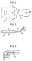
- FIGs 4 and 5 is a plan view and a schematic Side view of a frame according to the invention according to a fourth or a fifth embodiment shown.
- the fifth embodiment only differs from the fourth embodiment in that the attachment extension 26 relative to the frame is turned.
- Frames differ in the fourth and fifth embodiments in that the fastening extension 26 is formed in one layer, and by extending the base plate 20. Because in these embodiments the load asymmetrically from the attachment extension 26 in the frame 10 is initiated is a particularly stable connection between the base plate 20 and the cover plate 22 in the area of Transition to the attachment extension 26 necessary.
- tabs 40 which are formed on the base plate are and in corresponding recesses in the cover plate 22nd be folded over.
- FIGS. 1 to 3 there is a bore 32 as shown in FIGS. 1 to 3 are known, and additional bores 42 are provided, with which the cover plate 22 is fixed to the base plate 20 can be connected, for example by rivets.
- the attachment process 26 is provided with a constriction 34 so that a Deformation area is formed, the eccentric loading of the Frame can yield, so that there is no displacement of the cover plate 22 comes opposite the base plate 20.
- a passage 44 is formed around the mounting hole 28 . This increases the Security against tearing out of the fastening opening.
- a further type of fastening of the Cover plate 22 shown on the base plate 20 The base plate 20 and the cover plate 22 are bent twice, taking the turn an undercut is formed in the base plate, in which one through the Bend of the cover plate 22 engages formed nose 50.
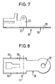
- the frame 10 consists of a base plate 20 and two side parts 60, which start from the base plate extend.
- the attachment extension 26 formed in one layer, so that no additional fasteners how rivets or screws are necessary.
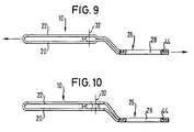
- FIGS. 9 and 10 illustrated further embodiments of the invention.
- This Embodiments largely correspond to those in FIGS. 2 and 3 illustrated embodiments, but the attachment extension 26 in those shown in Figures 9 and 10 Embodiments is angled.
- the extension of the base plate 20 points around the mounting opening 28 in these embodiments a passage 44 during the extension of the cover plate 22nd is provided with an opening which surrounds the passage 44 so that the two extensions of the base plate 20 and the cover plate 22 are secured against relative shifts.
- Such shifts could occur especially when the angled Attachment extension 26 due to a load on the frame in the sense stretched. This is through the two arrows indicated.
Landscapes
- Automotive Seat Belt Assembly (AREA)
- Buckles (AREA)
Abstract
Description
- Figur 1 in einem schematischen Querschnitt einen erfindungsgemäßen Rahmen gemäß einer ersten Ausführungsform;
- Figur 2 in einer schematischen Seitenansicht einen Teil eines erfindungsgemäßen Rahmens gemäß einer zweiten Ausführungsform;
- Figur 3 in einer Ansicht entsprechend derjenigen von Figur 2 eine dritte Ausführungsform der Erfindung;
- Figur 4 in einer schematischen Draufsicht einen erfindungsgemäßen Rahmen gemäß einer vierten Ausführungsform der Erfindung;
- Figur 5 in einer schematischen Seitenansicht einen erfindungsgemäßen Rahmen gemäß einer fünften Ausführungsform der Erfindung;
- Figur 6 in einer schematischen Seitenansicht ein Detail eines erfindungsgemäßen Rahmens;
- Figur 7 in einem schematischen Querschnitt einen erfindungsgemäßen Rahmen gemäß einer sechsten Ausführungsform der Erfindung;
- Figur 8 eine Draufsicht auf den in Figur 7 gezeigten Rahmen;
- Figur 9 in einer schematischen Seitenansicht einen erfindungsgemäßen Rahmen gemäß einer siebten Ausführungsform; und
- Figur 10 in einer schematischen Seitenansicht einen erfindungsgemäßen Rahmen gemäß einer achten Ausführungsform.
Claims (19)
- Lasttragender Rahmen aus Metall für ein Gurtschloß eines Fahrzeug-Sicherheitsgurtsystems, dadurch gekennzeichnet, daß ein Befestigungsfortsatz (26) vorgesehen ist, der einstückig mit dem Rahmen (10) ausgebildet und mit einer Befestigungsöffnung (28) für eine fahrzeugfeste Montage versehen ist.
- Rahmen nach Anspruch 1, dadurch gekennzeichnet, daß der Rahmen (10) durch eine Grundplatte (20) und eine zu dieser parallel verlaufende Abdeckplatte (22) gebildet ist, die auf der von dem Befestigungsfortsatz (26) abgewandten Seite einstückig miteinander verbunden sind.
- Rahmen nach Anspruch 2, dadurch gekennzeichnet, daß die Grundplatte (20) und die Abdeckplatte (22) auf ihrer dem Befestigungsfortsatz (26) zugewandten Seite aneinander befestigt sind.
- Rahmen nach Anspruch 3, gekennzeichnet, daß die Grundplatte (20) und die Abdeckplatte (22) auf ihrer dem Befestigungsfortsatz (26) zugewandten Seite miteinander vernietet sind.
- Rahmen nach Anspruch 3, dadurch gekennzeichnet, daß die Grundplatte (20) und die Abdeckplatte (22) auf ihrer dem Befestigungsfortsatz (26) zugewandten Seite miteinander durch umgelegte Blechlaschen (40) verbunden sind, die an der Grundplatte (20) oder der Abdeckplatte (22) ausgebildet sind und an der anderen Platte angreifen.
- Rahmen nach Anspruch 3, dadurch gekennzeichnet, daß die Grundplatte (20) und die Abdeckplatte (22) auf ihrer dem Befestigungsfortsatz (26) zugewandten Seite miteinander durch eine Biegestelle verbunden sind, an der die eine Platte einen Hinterschnitt bildet, in den eine an der andere Platte gebildete Nase (50) eingreift.
- Rahmen nach einem der Ansprüche 2 bis 6, dadurch gekennzeichnet, daß der Befestigungsfortsatz (26) durch eine Verlängerung der Grundplatte (20) und der Abdeckplatte (22) gebildet ist.
- Rahmen nach Anspruch 7, dadurch gekennzeichnet, daß die Verlängerung der Grundplatte (20) und die Verlängerung der Abdeckplatte (22) im Bereich der Befestigungsöffnung (28) aufeinanderliegen.
- Rahmen nach Anspruch 8, dadurch gekennzeichnet, daß in der Verlängerung der Grundplatte (20) bzw. der Abdeckplatte (22) ein Durchzug (44) ausgebildet ist, der in eine Öffnung in der anderen Verlängerung eingreift, so daß die beiden Verlängerungen durch Formschluß gegen Relativverschiebungen gesichert sind.
- Rahmen nach Anspruch 9, dadurch gekennzeichnet, daß der Durchzug (44) die Befestigungsöffnung (28) bildet.
- Rahmen nach Anspruch 7, dadurch gekennzeichnet, daß die Verlängerung der Grundplatte (20) und die Verlängerung der Abdeckplatte (22) in einem Bereich zwischen dem Rahmen (10) und der Befestigungsöffnung (28) aufeinanderliegen und im Bereich der Befestigungsöffnung (28) voneinander beabstandet sind.
- Rahmen nach Anspruch 11, dadurch gekennzeichnet, daß die Verlängerung der Grundplatte (20) und die Verlängerung der Abdeckplatte (22) im Bereich der Befestigungsöffnung (28) spiegelbildlich abgebogen sind, so daß eine symmetrische Gabel (30) gebildet ist.
- Rahmen nach Anspruch 11, dadurch gekennzeichnet, daß eine der Verlängerungen der Grundplatte (20) und der Abdeckplatte (22) geradlinig verläuft und die andere Verlängerung abgebogen ist, so daß eine asymmetrische Gabel (30) gebildet ist.
- Rahmen nach Anspruch 1, dadurch gekennzeichnet, daß der Rahmen (10) durch eine Grundplatte (20) und sich ausgehend von diesen erstreckenden Seitenteilen (60) gebildet ist.
- Rahmen nach einem der Ansprüche 2 bis 6 oder nach Anspruch 14, dadurch gekennzeichnet, daß der Befestigungsfortsatz (26) durch eine Verlängerung der Grundplatte (20) gebildet ist.
- Rahmen nach Anspruch 15, dadurch gekennzeichnet, daß die Befestigungsöffnung (28) mit einem Durchzug (44) versehen ist.
- Rahmen nach Anspruch 7 oder Anspruch 15, dadurch gekennzeichnet, daß der Befestigungsfortsatz (26) gegenüber dem Rahmen (10) abgebogen ist.
- Rahmen nach Anspruch 17, soweit dieser auf Anspruch 7 rückbezogen ist, dadurch gekennzeichnet, daß die Verlängerung der Grundplatte (20) und die Verlängerung der Abdeckplatte (22) im abgewickelten Zustand dieselbe Länge haben.
- Rahmen nach einem der vorhergehenden Ansprüche, dadurch gekennzeichnet, daß der Befestigungsfortsatz (26) zwischen dem Rahmen (10) und der Befestigungsöffnung (28) eine Einschnürung (34) aufweist.
Applications Claiming Priority (2)
| Application Number | Priority Date | Filing Date | Title |
|---|---|---|---|
| DE29701175U | 1997-01-24 | ||
| DE29701175U DE29701175U1 (de) | 1997-01-24 | 1997-01-24 | Lasttragender Rahmen aus Metall für ein Gurtschloß eines Fahrzeug-Sicherheitsgurtsystems |
Publications (2)
| Publication Number | Publication Date |
|---|---|
| EP0855152A2 true EP0855152A2 (de) | 1998-07-29 |
| EP0855152A3 EP0855152A3 (de) | 1999-01-07 |
Family
ID=8034979
Family Applications (1)
| Application Number | Title | Priority Date | Filing Date |
|---|---|---|---|
| EP98100290A Ceased EP0855152A3 (de) | 1997-01-24 | 1998-01-09 | Lasttragender Rahmen aus Metall für ein Gurtschloss eines Fahrzeug-sicherheitsgurtsystems |
Country Status (6)
| Country | Link |
|---|---|
| US (1) | US6360409B1 (de) |
| EP (1) | EP0855152A3 (de) |
| JP (1) | JPH10203303A (de) |
| KR (1) | KR19980070557A (de) |
| DE (1) | DE29701175U1 (de) |
| ES (1) | ES2128291T1 (de) |
Families Citing this family (2)
| Publication number | Priority date | Publication date | Assignee | Title |
|---|---|---|---|---|
| DE10323239A1 (de) * | 2003-05-22 | 2004-12-09 | Trw Occupant Restraint Systems Gmbh & Co. Kg | Fixierbeschlag |
| ITTO20060492A1 (it) * | 2006-07-04 | 2008-01-05 | Novarace S R L | Dispositivo di chiusura per cinture di ritenuta, particolarmente per seggiolini di sicurezza automobilistici per bambini |
Family Cites Families (16)
| Publication number | Priority date | Publication date | Assignee | Title |
|---|---|---|---|---|
| JPS5732742Y2 (de) * | 1977-09-20 | 1982-07-19 | ||
| DE2825181A1 (de) * | 1978-06-08 | 1979-12-13 | Autoflug Gmbh | Verankerungsteil fuer sicherheitsgurte |
| US4262396A (en) * | 1978-07-10 | 1981-04-21 | Nsk-Warner K. K. | Buckle assembly for vehicle seat belt |
| US4566160A (en) * | 1981-04-13 | 1986-01-28 | Irvin Industries, Inc. | End release inverse clevis buckle |
| DE3331453C2 (de) * | 1983-08-31 | 1987-04-23 | TRW Repa GmbH, 7077 Alfdorf | Gurtschloß für einen Sicherheitsgurt |
| US4550474A (en) * | 1983-11-21 | 1985-11-05 | Gateway Industries, Inc. | Safety belt buckle |
| NO155871C (no) * | 1985-03-28 | 1987-06-17 | Loyd S Industri As | Laas for sikkerhetsbelter og lignende. |
| FR2590134B1 (fr) * | 1985-11-20 | 1989-03-10 | Peugeot Aciers Et Outillage | Boucle de ceinture de securite, notamment pour vehicule automobile |
| US4702491A (en) * | 1986-10-30 | 1987-10-27 | Allied Corporation | Quick disconnect three point safety restraint system |
| FR2615808B1 (fr) * | 1987-05-27 | 1990-03-30 | Peugeot | Dispositif de fixation sur un vehicule d'un brin portant un systeme de verrouillage et de deverrouillage d'une ceinture de securite |
| US4945617A (en) * | 1989-03-20 | 1990-08-07 | General Motors Corporation | Seat belt buckle |
| JPH06217807A (ja) * | 1993-01-26 | 1994-08-09 | Takata Kk | 自動バックル装置 |
| US5438492A (en) * | 1993-03-26 | 1995-08-01 | Alliedsignal Inc. | End release seat belt buckle |
| US5377393A (en) * | 1993-09-03 | 1995-01-03 | Trw Vehicle Safety Systems Inc. | Seat belt buckle |
| DE29517162U1 (de) * | 1995-10-25 | 1996-01-25 | Trw Occupant Restraint Systems Gmbh, 73551 Alfdorf | Befestigungsbeschlag für ein Gurtschloß |
| DE29618509U1 (de) * | 1996-10-23 | 1997-02-20 | Trw Occupant Restraint Systems Gmbh, 73551 Alfdorf | Gurtschloß für einen Sicherheitsgurt |
-
1997
- 1997-01-24 DE DE29701175U patent/DE29701175U1/de not_active Expired - Lifetime
-
1998
- 1998-01-09 ES ES98100290T patent/ES2128291T1/es active Pending
- 1998-01-09 EP EP98100290A patent/EP0855152A3/de not_active Ceased
- 1998-01-16 KR KR1019980001112A patent/KR19980070557A/ko not_active Withdrawn
- 1998-01-23 JP JP10011509A patent/JPH10203303A/ja active Pending
- 1998-01-23 US US09/012,870 patent/US6360409B1/en not_active Expired - Fee Related
Non-Patent Citations (1)
| Title |
|---|
| None |
Also Published As
| Publication number | Publication date |
|---|---|
| US6360409B1 (en) | 2002-03-26 |
| KR19980070557A (ko) | 1998-10-26 |
| EP0855152A3 (de) | 1999-01-07 |
| ES2128291T1 (es) | 1999-05-16 |
| DE29701175U1 (de) | 1997-05-22 |
| JPH10203303A (ja) | 1998-08-04 |
Similar Documents
| Publication | Publication Date | Title |
|---|---|---|
| DE2936468C2 (de) | Vorrichtung zur Befestigung eines Instruments in einer Vertiefung der Armaturentafel eines Kraftfahrzeugs | |
| DE60131785T2 (de) | Zubehörbefestigungssystem für fahrzeuginnenräume | |
| DE10318220B4 (de) | Montagestruktur und Montageverfahren für Fahrzeuginnenteile | |
| EP2123918B1 (de) | Befestigungselement | |
| DE10297288B4 (de) | Lasche zur Einstellung der Z-Höhe eines Airbagmoduls | |
| DE112007002400T5 (de) | Bandschelle zum Sichern einer Aufblaseinrichtung an einem Airbagmodulgehäuse | |
| EP2432666A2 (de) | Befestigungselement und verfahren zum befestigen eines gassacks eines fahrzeuginsassen-rückhaltesystems an einer fahrzeugstruktur | |
| DE102017208726B4 (de) | Sitzlängsverstellvorrichtung | |
| EP1687164B1 (de) | Aggregateträger mit integrierter schlossbefestigung für eine kraftfahrzeugtür | |
| EP0838173A2 (de) | Gurtschloss für einen Sicherheitsgurt | |
| EP0855152A2 (de) | Lasttragender Rahmen aus Metall für ein Gurtschloss eines Fahrzeug-sicherheitsgurtsystems | |
| DE29812707U1 (de) | Befestigungsvorrichtung für flächige Bauteile | |
| DE202012007754U1 (de) | Clip-, Stift- und Halterungsbaugruppe zur Befestigung von Zubehörteilen an Fahrzeugpaneelen | |
| DE102024125190A1 (de) | Verbesserte befestigungsklammer | |
| EP1787875A1 (de) | Rahmen für einen Sicherheitsgurtaufroller | |
| DE102008031880B4 (de) | Befestigungselement für das Spannband einer Seitenairbaganordnung | |
| DE102007012039A1 (de) | Seilschuh für eine Sicherheitsgurtanbringung und Baugruppe bestehend aus einem solchen Seilschuh und einem Seil | |
| DE102007018550B3 (de) | Aufsatz für ein Gurtschloss | |
| DE3343104A1 (de) | Vorrichtung zum befestigen des gehaeuses einer automatischen aufrolleinrichtung fuer sicherheitsgurte und deren end- und umlenkbeschlaege | |
| DE10322569B4 (de) | Verzurrhalterung zur Anbringung an einem Träger | |
| DE102020002900A1 (de) | Gurtbandführungselement | |
| DE102023130072A1 (de) | Schubkasten und Verfahren zur Herstellung eines Schubkastens | |
| DE10029817A1 (de) | Vorrichtung zur Befestigung eines Airbagmoduls | |
| DE3337508A1 (de) | Gurtschloss fuer einen sicherheitsgurt | |
| DE102006004852A1 (de) | Gurtzeug für Gleitschirmpiloten |
Legal Events
| Date | Code | Title | Description |
|---|---|---|---|
| PUAI | Public reference made under article 153(3) epc to a published international application that has entered the european phase |
Free format text: ORIGINAL CODE: 0009012 |
|
| AK | Designated contracting states |
Kind code of ref document: A2 Designated state(s): DE ES FR GB IT |
|
| AX | Request for extension of the european patent |
Free format text: AL;LT;LV;MK;RO;SI |
|
| PUAL | Search report despatched |
Free format text: ORIGINAL CODE: 0009013 |
|
| AK | Designated contracting states |
Kind code of ref document: A3 Designated state(s): AT BE CH DE DK ES FI FR GB GR IE IT LI LU MC NL PT SE |
|
| AX | Request for extension of the european patent |
Free format text: AL;LT;LV;MK;RO;SI |
|
| GBC | Gb: translation of claims filed (gb section 78(7)/1977) | ||
| ITCL | It: translation for ep claims filed |
Representative=s name: DR. ING. A. RACHELI & C. |
|
| EL | Fr: translation of claims filed | ||
| REG | Reference to a national code |
Ref country code: ES Ref legal event code: BA2A Ref document number: 2128291 Country of ref document: ES Kind code of ref document: T1 |
|
| 17P | Request for examination filed |
Effective date: 19990420 |
|
| AKX | Designation fees paid |
Free format text: DE ES FR GB IT |
|
| 17Q | First examination report despatched |
Effective date: 20020405 |
|
| STAA | Information on the status of an ep patent application or granted ep patent |
Free format text: STATUS: THE APPLICATION HAS BEEN REFUSED |
|
| 18R | Application refused |
Effective date: 20040313 |