EP0855152A2 - Metallic load carrying frame for a vehicle safety belt buckle - Google Patents
Metallic load carrying frame for a vehicle safety belt buckle Download PDFInfo
- Publication number
- EP0855152A2 EP0855152A2 EP98100290A EP98100290A EP0855152A2 EP 0855152 A2 EP0855152 A2 EP 0855152A2 EP 98100290 A EP98100290 A EP 98100290A EP 98100290 A EP98100290 A EP 98100290A EP 0855152 A2 EP0855152 A2 EP 0855152A2
- Authority
- EP
- European Patent Office
- Prior art keywords
- extension
- base plate
- frame according
- cover plate
- frame
- Prior art date
- Legal status (The legal status is an assumption and is not a legal conclusion. Google has not performed a legal analysis and makes no representation as to the accuracy of the status listed.)
- Ceased
Links
- 239000002184 metal Substances 0.000 claims abstract description 7
- 238000005452 bending Methods 0.000 claims description 2
- 238000000034 method Methods 0.000 description 5
- 238000006073 displacement reaction Methods 0.000 description 2
- 230000015572 biosynthetic process Effects 0.000 description 1
- 238000004519 manufacturing process Methods 0.000 description 1
- 238000004080 punching Methods 0.000 description 1
- 238000003860 storage Methods 0.000 description 1
- 230000007704 transition Effects 0.000 description 1
Images

Classifications
-
- A—HUMAN NECESSITIES
- A44—HABERDASHERY; JEWELLERY
- A44B—BUTTONS, PINS, BUCKLES, SLIDE FASTENERS, OR THE LIKE
- A44B11/00—Buckles; Similar fasteners for interconnecting straps or the like, e.g. for safety belts
- A44B11/25—Buckles; Similar fasteners for interconnecting straps or the like, e.g. for safety belts with two or more separable parts
- A44B11/2503—Safety buckles
- A44B11/2546—Details
- A44B11/2561—Tongue elements
-
- Y—GENERAL TAGGING OF NEW TECHNOLOGICAL DEVELOPMENTS; GENERAL TAGGING OF CROSS-SECTIONAL TECHNOLOGIES SPANNING OVER SEVERAL SECTIONS OF THE IPC; TECHNICAL SUBJECTS COVERED BY FORMER USPC CROSS-REFERENCE ART COLLECTIONS [XRACs] AND DIGESTS
- Y10—TECHNICAL SUBJECTS COVERED BY FORMER USPC
- Y10T—TECHNICAL SUBJECTS COVERED BY FORMER US CLASSIFICATION
- Y10T24/00—Buckles, buttons, clasps, etc.
- Y10T24/45—Separable-fastener or required component thereof [e.g., projection and cavity to complete interlock]
- Y10T24/45225—Separable-fastener or required component thereof [e.g., projection and cavity to complete interlock] including member having distinct formations and mating member selectively interlocking therewith
- Y10T24/45602—Receiving member includes either movable connection between interlocking components or variable configuration cavity
- Y10T24/45623—Receiving member includes either movable connection between interlocking components or variable configuration cavity and operator therefor
- Y10T24/4566—Receiving member includes either movable connection between interlocking components or variable configuration cavity and operator therefor including slidably connected and guided element on receiving member
- Y10T24/4567—Receiving member includes either movable connection between interlocking components or variable configuration cavity and operator therefor including slidably connected and guided element on receiving member for shifting slidably connected and guided, nonself-biasing, interlocking component
Definitions
- the invention relates to a load-bearing frame made of metal for a buckle of a vehicle seat belt system.
- Such a frame takes the usual functional parts of one Belt buckle on, for example a locking bolt for one in the Buckle to be inserted, a locking mechanism for the locking bolt, a release button, a panel, etc.
- a wire rope or a metal ash is used with one end on the vehicle and the other end on the load bearing Frame of the buckle is attached.
- a load-bearing frame is according to the invention characterized in that a fastening extension is provided, which is integrally formed with the frame and with a mounting opening is provided for a vehicle-fixed assembly.
- Vehicle-fixed assembly is the attachment of the belt buckle understood part of the vehicle, either directly or using a flexible element that is limited Allows the buckle to move.
- the invention is therefore based then, usually for connecting the buckle to the Separate fastening element provided by a vehicle fastening projection formed in one piece with the frame replace.
- the framework of the Belt buckle can be dimensioned more favorably, since there is a special uniform flow of force between the attachment process and the Results in a framework that is not due to the usually existing Connecting links between the fastening element and the frame, for example rivets or screws. This results in also a lower weight. Leaves almost no additional effort a variety of different attachment processes achieve; since the frame is usually punched out of sheet metal only a different punching tool is necessary.
- FIG. 1 is a schematic cross section load-bearing frame 10 according to a first embodiment of the Invention shown.
- This frame 10 forms a receptacle for one Tongue 14 of a seat belt system, not shown.
- To the Frame 10 are the known functional parts of a buckle attached, for example the schematically illustrated housing 16, a (not shown) locking bolt for the tongue 14 and a (Not shown) release button for the locking bolt.
- the load-bearing frame 10 is stamped from sheet metal and has a base plate 20 and a cover plate 22 on the side, on which the tongue 14 is inserted, in one piece with one another are connected by a bending point 24.
- On the tongue 14 opposite side is the frame 10 with an attachment extension 26 provided by an extension of the base plate 20 and a Extension of the cover plate 22 is formed.
- the attachment process 26 is with a schematically illustrated fastening opening 28 provided in which, for example, engage a fastening screw with which the frame can be attached to the vehicle, for example on a vehicle seat.
- the attachment extension 26 forming extensions of the base plate 20 and the cover plate 22nd lie flat on top of one another in the area of the attachment extension 26.
- FIG 2 is the attachment extension of an inventive Frame shown according to a second embodiment.
- the Fastening extension 26 is elongated in this embodiment, to attach the buckle to a concealed one Allow attachment point.
- the extensions of the extension 26 forming the Base plate 20 and the cover plate 22 flat on one another; only in In the area of the fastening opening 28, the two extensions are bent, so that a symmetrical fork 30 is formed.
- the base plate 20 and the cover plate 22 are at their Attachment extension 26 facing side connected. To rivets or screws can be used for this purpose extend through a schematically illustrated opening 32.
- FIG. 3 is schematically the attachment extension of a load-bearing Frame according to a third embodiment of the invention shown.
- the frame, the attachment extension 26 and the fork 30 symmetrical are configured to a central plane, which is formed by the Touch level of the two extensions of the base plate 20 and Cover plate 22 in the area of the attachment extension 26 are the Frame 10 and fork 30 asymmetrical in this embodiment designed.
- the base plate 20 goes straight into the extension for the attachment extension 26 while the cover plate 22 by means of a bend in the extension for the attachment extension 26 transforms.
- the extension of the base plate 20 is for formation the fork 30 is bent while the extension of the cover plate 22nd continues in a straight line.
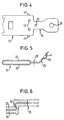
- FIGs 4 and 5 is a plan view and a schematic Side view of a frame according to the invention according to a fourth or a fifth embodiment shown.
- the fifth embodiment only differs from the fourth embodiment in that the attachment extension 26 relative to the frame is turned.
- Frames differ in the fourth and fifth embodiments in that the fastening extension 26 is formed in one layer, and by extending the base plate 20. Because in these embodiments the load asymmetrically from the attachment extension 26 in the frame 10 is initiated is a particularly stable connection between the base plate 20 and the cover plate 22 in the area of Transition to the attachment extension 26 necessary.
- tabs 40 which are formed on the base plate are and in corresponding recesses in the cover plate 22nd be folded over.
- FIGS. 1 to 3 there is a bore 32 as shown in FIGS. 1 to 3 are known, and additional bores 42 are provided, with which the cover plate 22 is fixed to the base plate 20 can be connected, for example by rivets.
- the attachment process 26 is provided with a constriction 34 so that a Deformation area is formed, the eccentric loading of the Frame can yield, so that there is no displacement of the cover plate 22 comes opposite the base plate 20.
- a passage 44 is formed around the mounting hole 28 . This increases the Security against tearing out of the fastening opening.
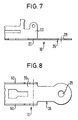
- a further type of fastening of the Cover plate 22 shown on the base plate 20 The base plate 20 and the cover plate 22 are bent twice, taking the turn an undercut is formed in the base plate, in which one through the Bend of the cover plate 22 engages formed nose 50.
- the frame 10 consists of a base plate 20 and two side parts 60, which start from the base plate extend.
- the attachment extension 26 formed in one layer, so that no additional fasteners how rivets or screws are necessary.
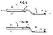
- FIGS. 9 and 10 illustrated further embodiments of the invention.
- This Embodiments largely correspond to those in FIGS. 2 and 3 illustrated embodiments, but the attachment extension 26 in those shown in Figures 9 and 10 Embodiments is angled.
- the extension of the base plate 20 points around the mounting opening 28 in these embodiments a passage 44 during the extension of the cover plate 22nd is provided with an opening which surrounds the passage 44 so that the two extensions of the base plate 20 and the cover plate 22 are secured against relative shifts.
- Such shifts could occur especially when the angled Attachment extension 26 due to a load on the frame in the sense stretched. This is through the two arrows indicated.
Landscapes
- Automotive Seat Belt Assembly (AREA)
- Buckles (AREA)
Abstract
Description
Die Erfindung betrifft einen lasttragenden Rahmen aus Metall für ein Gurtschloß eines Fahrzeug-Sicherheitsgurtsystems.The invention relates to a load-bearing frame made of metal for a buckle of a vehicle seat belt system.
Ein solcher Rahmen nimmt die üblichen Funktionsteile eines Gurtschlosses auf, beispielsweise einen Sperriegel für eine in das Gurtschloß einzusteckende Steckzunge, einen Verriegelungsmechanismus für den Sperriegel, eine Lösetaste, eine Verkleidung, etc. Für die Befestigung des Gurtschlosses mit dem Fahrzeug wird üblicherweise entweder ein Drahtseil oder eine Metallasche verwendet, das bzw. die mit einem Ende am Fahrzeug und mit dem anderen Ende am lasttragenden Rahmen des Gurtschlosses befestigt wird.Such a frame takes the usual functional parts of one Belt buckle on, for example a locking bolt for one in the Buckle to be inserted, a locking mechanism for the locking bolt, a release button, a panel, etc. For the Fastening the belt buckle to the vehicle is usually done either a wire rope or a metal ash is used with one end on the vehicle and the other end on the load bearing Frame of the buckle is attached.
Im Gegensatz dazu ist ein lasttragender Rahmen gemäß der Erfindung dadurch gekennzeichnet, daß ein Befestigungsfortsatz vorgesehen ist, der einstückig mit dem Rahmen ausgebildet und mit einer Befestigungsöffnung für eine fahrzeugfeste Montage versehen ist. Unter "fahrzeugfeste Montage" wird dabei die Anbringung des Gurtschlosses an einem Teil des Fahrzeugs verstanden, und zwar entweder direkt oder unter Verwendung eines flexiblen Elements, das eine begrenzte Beweglichkeit des Gurtschlosses ermöglicht. Die Erfindung beruht also darauf, das üblicherweise zur Verbindung des Gurtschlosses mit dem Fahrzeug vorgesehene separate Befestigungselement durch einen einstückig mit dem Rahmen ausgebildeten Befestigungsfortsatz zu ersetzen. Dies bringt eine Reihe von Vorteilen. Zum einen ergeben sich geringere Kosten. Dies ist darauf zurückzuführen, daß ein einstückig mit dem Rahmen ausgebildeter Befestigungsfortsatz billiger herzustellen ist als ein getrenntes Befestigungselement, da für die Bildung des Befestigungsfortsatzes nahezu keine zusätzlichen Arbeitsschritte benötigt werden. Ferner entfallen Bevorratungs- und Transportkosten für das zusätzliche Befestigungselement. Weiterhin kann der Rahmen des Gurtschlosses günstiger dimensioniert werden, da sich ein besonders gleichmäßiger Kraftfluß zwischen dem Befestigungsfortsatz und dem Rahmen ergibt, der nicht durch die üblicherweise vorhandenen Verbindungsglieder zwischen dem Befestigungselement und dem Rahmen, beispielsweise Niete oder Schrauben, gestört wird. Dadurch ergibt sich auch ein geringerese Gewicht. Nahezu ohne zusätzlichen Aufwand läßt sich eine Vielzahl von unterschiedlichen Befestigungsfortsätzen erzielen; da der Rahmen üblicherweise aus Blech ausgestanzt wird, ist lediglich ein anderes Stanzwerkzeug notwendig.In contrast, a load-bearing frame is according to the invention characterized in that a fastening extension is provided, which is integrally formed with the frame and with a mounting opening is provided for a vehicle-fixed assembly. Under "Vehicle-fixed assembly" is the attachment of the belt buckle understood part of the vehicle, either directly or using a flexible element that is limited Allows the buckle to move. The invention is therefore based then, usually for connecting the buckle to the Separate fastening element provided by a vehicle fastening projection formed in one piece with the frame replace. This has a number of advantages. On the one hand arise lower costs. This is due to the fact that one piece with the frame trained attachment extension cheaper to manufacture is as a separate fastener because for education the attachment process almost no additional steps are needed. Furthermore, there are no storage and transport costs for the additional fastener. Furthermore, the framework of the Belt buckle can be dimensioned more favorably, since there is a special uniform flow of force between the attachment process and the Results in a framework that is not due to the usually existing Connecting links between the fastening element and the frame, for example rivets or screws. This results in also a lower weight. Leaves almost no additional effort a variety of different attachment processes achieve; since the frame is usually punched out of sheet metal only a different punching tool is necessary.
Weitere Merkmale der Erfindung ergeben sich aus den Unteransprüchen.Further features of the invention result from the Subclaims.
Die Erfindung wird nachfolgend unter Bezugnahme auf die beigefügten Zeichnungen beschrieben. In diesen zeigen:
- Figur 1 in einem schematischen Querschnitt einen erfindungsgemäßen Rahmen gemäß einer ersten Ausführungsform;
- Figur 2 in einer schematischen Seitenansicht einen Teil eines erfindungsgemäßen Rahmens gemäß einer zweiten Ausführungsform;
- Figur 3 in einer Ansicht entsprechend derjenigen von Figur 2 eine dritte Ausführungsform der Erfindung;
- Figur 4 in einer schematischen Draufsicht einen erfindungsgemäßen Rahmen gemäß einer vierten Ausführungsform der Erfindung;
- Figur 5 in einer schematischen Seitenansicht einen erfindungsgemäßen Rahmen gemäß einer fünften Ausführungsform der Erfindung;
- Figur 6 in einer schematischen Seitenansicht ein Detail eines erfindungsgemäßen Rahmens;
- Figur 7 in einem schematischen Querschnitt einen erfindungsgemäßen Rahmen gemäß einer sechsten Ausführungsform der Erfindung;
- Figur 8 eine Draufsicht auf den in Figur 7 gezeigten Rahmen;
- Figur 9 in einer schematischen Seitenansicht einen erfindungsgemäßen Rahmen gemäß einer siebten Ausführungsform; und
Figur 10 in einer schematischen Seitenansicht einen erfindungsgemäßen Rahmen gemäß einer achten Ausführungsform.
- Figure 1 is a schematic cross section of a frame according to the invention according to a first embodiment;
- Figure 2 is a schematic side view of part of a frame according to the invention according to a second embodiment;
- Figure 3 is a view corresponding to that of Figure 2 shows a third embodiment of the invention;
- Figure 4 is a schematic plan view of a frame according to the invention according to a fourth embodiment of the invention;
- Figure 5 is a schematic side view of a frame according to the invention according to a fifth embodiment of the invention;
- Figure 6 is a schematic side view of a detail of a frame according to the invention;
- Figure 7 is a schematic cross section of a frame according to the invention according to a sixth embodiment of the invention;
- Figure 8 is a plan view of the frame shown in Figure 7;
- Figure 9 is a schematic side view of a frame according to the invention according to a seventh embodiment; and
- Figure 10 is a schematic side view of a frame according to the invention according to an eighth embodiment.
In Figur 1 ist in einem schematischen Querschnitt ein
lasttragender Rahmen 10 gemäß einer ersten Ausführungsform der
Erfindung dargestellt. Dieser Rahmen 10 bildet eine Aufnahme für eine
Steckzunge 14 eines nicht dargestellten Sicherheitsgurtsystems. An dem
Rahmen 10 sind die bekannten Funktionsteile eines Gurtschlosses
angebracht, beispielsweise das schematisch dargestellte Gehäuse 16,
ein (nicht dargestellter) Sperriegel für die Steckzunge 14 sowie eine
(nicht dargestellte) Lösetaste für den Sperriegel.In Figure 1 is a schematic cross section
load-bearing
Der lasttragende Rahmen 10 ist aus Metallblech gestanzt und weist
eine Grundplatte 20 sowie eine Abdeckplatte 22 auf, die auf der Seite,
an der die Steckzunge 14 eingesteckt wird, einstückig miteinander
durch eine Biegestelle 24 verbunden sind. Auf der von der Steckzunge
14 abgewandten Seite ist der Rahmen 10 mit einem Befestigungsfortsatz
26 versehen, der durch eine Verlängerung der Grundplatte 20 und eine
Verlängerung der Abdeckplatte 22 gebildet ist. Der Befestigungsfortsatz
26 ist mit einer schematisch dargestellten Befestigungsöffnung 28
versehen, in die beispielsweise eine Befestigungsschraube eingreifen
kann, mit der der Rahmen fahrzeugfest angebracht werden kann,
beispielsweise an einem Fahrzeugsitz. Die den Befestigungsfortsatz 26
bildenden Verlängerungen der Grundplatte 20 und der Abdeckplatte 22
liegen im Bereich des Befestigungsfortsatzes 26 flach aufeinander.The load-bearing
In Figur 2 ist der Befestigungsfortsatz eines erfindungsgemäßen
Rahmens gemäß einer zweiten Ausführungsform dargestellt. Der
Befestigungsfortsatz 26 ist bei dieser Ausführungsform langgestreckt,
um die Befestigung des Gurtschlosses an einem verdeckt liegenden
Befestigungspunkt zu ermöglichen. Auch bei dieser Ausführungsform
liegen die den Befestigungsfortsatz 26 bildenden Verlängerungen der
Grundplatte 20 und der Abdeckplatte 22 flach aufeinander; lediglich im
Bereich der Befestigungsöffnung 28 sind die beiden Fortsätze abgebogen,
so daß eine symmetrische Gabel 30 gebildet ist.In Figure 2 is the attachment extension of an inventive
Frame shown according to a second embodiment. Of the
Die Grundplatte 20 und die Abdeckplatte 22 sind an ihrer dem
Befestigungsfortsatz 26 zugewandten Seite miteinander verbunden. Zu
diesem Zweck können Niete oder Schrauben verwendet werden, die sich
durch eine schematisch dargestellte Öffnung 32 erstrecken.The
In Figur 3 ist schematisch der Befestigungsfortsatz eines lasttragenden
Rahmens gemäß einer dritten Ausführungsform der Erfindung
dargestellt. Im Gegensatz zur Ausführungsform gemäß Figur 2, bei der
der Rahmen, der Befestigungsfortsatz 26 und die Gabel 30 symmetrisch
zu einer Mittelebene ausgestaltet sind, die gebildet ist durch die
Berührebene der beiden Verlängerungen der Grundplatte 20 und der
Abdeckplatte 22 im Bereich des Befestigungsfortsatzes 26, sind der
Rahmen 10 und die Gabel 30 bei dieser Ausführungsform asymmetrisch
gestaltet. Die Grundplatte 20 geht geradlinig in die Verlängerung für
den Befestigungsfortsatz 26 über, während die Abdeckplatte 22 mittels
einer Abbiegung in die Verlängerung für den Befestigungsfortsatz 26
übergeht. Dagegen ist die Verlängerung der Grundplatte 20 zur Bildung
der Gabel 30 abgebogen, während die Verlängerung der Abdeckplatte 22
geradlinig weiterläuft. In Figure 3 is schematically the attachment extension of a load-bearing
Frame according to a third embodiment of the invention
shown. In contrast to the embodiment according to FIG. 2, in which
the frame, the
In den Figuren 4 und 5 ist schematisch eine Draufsicht bzw. eine
Seitenansicht eines erfindungsgemäßen Rahmens gemäß einer vierten bzw.
einer fünften Ausführungsform dargestellt. Die fünfte Ausführungsform
unterscheidet sich von der vierten Ausführungsform lediglich
dahingehend, daß der Befestigungsfortsatz 26 gegenüber dem Rahmen
abgebogen ist. Gegenüber den in den Figuren 1 bis 3 dargestellten
Rahmen unterscheiden sich die vierte und die fünfte Ausführungsform
dadurch, daß der Befestigungsfortsatz 26 einlagig ausgebildet ist, und
zwar durch Verlängerung der Grundplatte 20. Da bei diesen Ausführungsformen
die Belastung asymmetrisch aus dem Befestigungsfortsatz 26 in
den Rahmen 10 eingeleitet wird, ist eine besonders stabile Verbindung
zwischen der Grundplatte 20 und der Abdeckplatte 22 im Bereich des
Übergangs zum Befestigungsfortsatz 26 notwendig. Zu diesem Zweck
können Laschen 40 vorgesehen sein, die an der Grundplatte gebildet
sind und in entsprechende Ausnehmungen in der Abdeckplatte 22
umgefaltet werden. Zusätzlich sind eine Bohrung 32, wie sie aus den
Figuren 1 bis 3 bekannt ist, sowie zusätzliche Bohrungen 42 vorgesehen,
mit denen die Abdeckplatte 22 fest mit der Grundplatte 20
verbunden werden kann, beispielsweise durch Niete. Der Befestigungsfortsatz
26 ist mit einer Einschnürung 34 versehen, so daß ein
Deformationsbereich gebildet ist, der bei exzentrischer Belastung des
Rahmens nachgeben kann, so daß es zu keiner Verschiebung der Abdeckplatte
22 gegenüber der Grundplatte 20 kommt. Um die Befestigungsöffnung
28 herum ist ein Durchzug 44 gebildet. Dies erhöht die
Sicherheit gegen Ausreißen der Befestigungsöffnung.In Figures 4 and 5 is a plan view and a schematic
Side view of a frame according to the invention according to a fourth or
a fifth embodiment shown. The fifth embodiment
only differs from the fourth embodiment
in that the
In Figur 6 ist schematisch eine weitere Art der Befestigung der
Abdeckplatte 22 an der Grundplatte 20 dargestellt. Die Grundplatte 20
und die Abdeckplatte 22 sind doppelt abgebogen, wobei an der Abbiegung
der Grundplatte ein Hinterschnitt gebildet ist, in den eine durch die
Abbiegung der Abdeckplatte 22 gebildete Nase 50 eingreift.A further type of fastening of the
In den Figuren 7 und 8 ist schematisch eine weitere
Ausführungsform der Erfindung dargestellt. Gemäß dieser
Ausführungsform besteht der Rahmen 10 aus einer Grundplatte 20 und
zwei Seitenteilen 60, die sich ausgehend von der Grundplatte
erstrecken. Bei dieser Ausführungsform ist der Befestigungsfortsatz 26
einlagig ausgebildet, so daß keine zusätzlichen Befestigungselemente
wie Niete oder Schrauben notwendig sind.Another is shown schematically in FIGS. 7 and 8
Embodiment of the invention shown. According to this
Embodiment, the
In den Figuren 9 und 10 ist schematisch ein Rahmen 10 gemaß
weiteren Ausführungsformen der Erfindung dargestellt. Diese
Ausführungsformen entsprechen weitestgehend den in den Figuren 2 und 3
dargestellten Ausführungsformen, wobei allerdings der Befestigungsfortsatz
26 bei den in den Figuren 9 und 10 dargestellten
Ausführungsformen abgewinkelt ist. Die Verlängerung der Grundplatte 20
weist bei diesen Ausführungsformen um die Befestigungsöffnung 28 herum
einen Durchzug 44 auf, während die Verlängerung der Abdeckplatte 22
mit einer Öffnung versehen ist, die den Durchzug 44 umgreift, so daß
die beiden Verlängerungen der Grundplatte 20 bzw. der Abdeckplatte 22
gegen Relativverschiebungen gesichert sind. Solche Verschiebungen
könnten insbesondere dann auftreten, wenn der abgewinkelte
Befestigungsfortsatz 26 aufgrund einer Belastung des Rahmens im Sinne
einer Streckung belastet wird. Dies ist durch die beiden Pfeile
angedeutet. Um zu verhindern, daß bei einer solchen Belastung eine
Verschiebung der Abdeckplatte 22 gegenüber der Grundplatte 20
auftritt, sind bei der in Figur 9 dargestellten Ausführungsform die
Verlängerungen der Grundplatte 20 bzw. der Abdeckplatte 22 so
ausgeführt, daß sie im abgewickelten, also gestreckten Zustand
dieselbe Länge haben. Bei der in Figur 10 dargestellten
Ausführungsform ist, um eine Relativverschiebung zwischen der
Grundplatte und der Abdeckplatte zu verhindern, eine Vernietung 32 der
beiden Platten aneinander vorgesehen.A
Claims (19)
Applications Claiming Priority (2)
| Application Number | Priority Date | Filing Date | Title |
|---|---|---|---|
| DE29701175U | 1997-01-24 | ||
| DE29701175U DE29701175U1 (en) | 1997-01-24 | 1997-01-24 | Load-bearing frame made of metal for a belt buckle of a vehicle seat belt system |
Publications (2)
| Publication Number | Publication Date |
|---|---|
| EP0855152A2 true EP0855152A2 (en) | 1998-07-29 |
| EP0855152A3 EP0855152A3 (en) | 1999-01-07 |
Family
ID=8034979
Family Applications (1)
| Application Number | Title | Priority Date | Filing Date |
|---|---|---|---|
| EP98100290A Ceased EP0855152A3 (en) | 1997-01-24 | 1998-01-09 | Metallic load carrying frame for a vehicle safety belt buckle |
Country Status (6)
| Country | Link |
|---|---|
| US (1) | US6360409B1 (en) |
| EP (1) | EP0855152A3 (en) |
| JP (1) | JPH10203303A (en) |
| KR (1) | KR19980070557A (en) |
| DE (1) | DE29701175U1 (en) |
| ES (1) | ES2128291T1 (en) |
Families Citing this family (2)
| Publication number | Priority date | Publication date | Assignee | Title |
|---|---|---|---|---|
| DE10323239A1 (en) * | 2003-05-22 | 2004-12-09 | Trw Occupant Restraint Systems Gmbh & Co. Kg | Fastening fitting for occupant restraint system in vehicle has retaining plate connected to baseplate by bridge and formed in two layers, whereby fold edge of retaining plate forms rounded guide edge |
| ITTO20060492A1 (en) * | 2006-07-04 | 2008-01-05 | Novarace S R L | CLOSING DEVICE FOR RETAINING BELTS, PARTICULARLY FOR AUTOMOTIVE SAFETY SEATS FOR CHILDREN |
Family Cites Families (16)
| Publication number | Priority date | Publication date | Assignee | Title |
|---|---|---|---|---|
| JPS5732742Y2 (en) * | 1977-09-20 | 1982-07-19 | ||
| DE2825181A1 (en) * | 1978-06-08 | 1979-12-13 | Autoflug Gmbh | Vehicle seat belt anchoring link - comprises tough bendable flat material narrowly necked for part of its length |
| US4262396A (en) * | 1978-07-10 | 1981-04-21 | Nsk-Warner K. K. | Buckle assembly for vehicle seat belt |
| US4566160A (en) * | 1981-04-13 | 1986-01-28 | Irvin Industries, Inc. | End release inverse clevis buckle |
| DE3331453C2 (en) * | 1983-08-31 | 1987-04-23 | TRW Repa GmbH, 7077 Alfdorf | Buckle for a seat belt |
| US4550474A (en) * | 1983-11-21 | 1985-11-05 | Gateway Industries, Inc. | Safety belt buckle |
| NO155871C (en) * | 1985-03-28 | 1987-06-17 | Loyd S Industri As | LOCK FOR SAFETY BELTS AND SIMILAR. |
| FR2590134B1 (en) * | 1985-11-20 | 1989-03-10 | Peugeot Aciers Et Outillage | SEAT BELT BUCKLE, ESPECIALLY FOR A MOTOR VEHICLE |
| US4702491A (en) * | 1986-10-30 | 1987-10-27 | Allied Corporation | Quick disconnect three point safety restraint system |
| FR2615808B1 (en) * | 1987-05-27 | 1990-03-30 | Peugeot | DEVICE FOR ATTACHING A VEHICLE TO A STRAND CARRYING A LOCKING AND UNLOCKING SYSTEM OF A SEAT BELT |
| US4945617A (en) * | 1989-03-20 | 1990-08-07 | General Motors Corporation | Seat belt buckle |
| JPH06217807A (en) * | 1993-01-26 | 1994-08-09 | Takata Kk | Automatic buckle device |
| US5438492A (en) * | 1993-03-26 | 1995-08-01 | Alliedsignal Inc. | End release seat belt buckle |
| US5377393A (en) * | 1993-09-03 | 1995-01-03 | Trw Vehicle Safety Systems Inc. | Seat belt buckle |
| DE29517162U1 (en) * | 1995-10-25 | 1996-01-25 | Trw Occupant Restraint Systems Gmbh, 73551 Alfdorf | Fastening fitting for a buckle |
| DE29618509U1 (en) * | 1996-10-23 | 1997-02-20 | Trw Occupant Restraint Systems Gmbh, 73551 Alfdorf | Belt buckle for a seat belt |
-
1997
- 1997-01-24 DE DE29701175U patent/DE29701175U1/en not_active Expired - Lifetime
-
1998
- 1998-01-09 ES ES98100290T patent/ES2128291T1/en active Pending
- 1998-01-09 EP EP98100290A patent/EP0855152A3/en not_active Ceased
- 1998-01-16 KR KR1019980001112A patent/KR19980070557A/en not_active Withdrawn
- 1998-01-23 JP JP10011509A patent/JPH10203303A/en active Pending
- 1998-01-23 US US09/012,870 patent/US6360409B1/en not_active Expired - Fee Related
Non-Patent Citations (1)
| Title |
|---|
| None |
Also Published As
| Publication number | Publication date |
|---|---|
| US6360409B1 (en) | 2002-03-26 |
| KR19980070557A (en) | 1998-10-26 |
| EP0855152A3 (en) | 1999-01-07 |
| ES2128291T1 (en) | 1999-05-16 |
| DE29701175U1 (en) | 1997-05-22 |
| JPH10203303A (en) | 1998-08-04 |
Similar Documents
| Publication | Publication Date | Title |
|---|---|---|
| DE2936468C2 (en) | Device for fastening an instrument in a recess in the dashboard of a motor vehicle | |
| DE60131785T2 (en) | ACCESSORIES FOR VEHICLE INTERIORS | |
| DE10318220B4 (en) | Assembly structure and assembly process for vehicle interior parts | |
| EP2123918B1 (en) | Fastening device | |
| DE10297288B4 (en) | Tab for adjusting the Z-height of an airbag module | |
| DE112007002400T5 (en) | Band clamp for securing an inflator to an air bag module housing | |
| EP2432666A2 (en) | Fastening element and method for fastening an airbag of a vehicle occupant restraint system to a vehicle structure | |
| DE102017208726B4 (en) | Seat length adjustment device | |
| EP1687164B1 (en) | Unit carrier comprising an integrated lock fixing system for a motor vehicle door | |
| EP0838173A2 (en) | Buckle for a safety belt | |
| EP0855152A2 (en) | Metallic load carrying frame for a vehicle safety belt buckle | |
| DE29812707U1 (en) | Fastening device for flat components | |
| DE202012007754U1 (en) | Clip, pin and bracket assembly for attaching accessories to vehicle panels | |
| DE102024125190A1 (en) | IMPROVED MOUNTING CLAMP | |
| EP1787875A1 (en) | Frame for a belt retractor of a safety belt | |
| DE102008031880B4 (en) | Fastener for the strap of a side airbag assembly | |
| DE102007012039A1 (en) | Cable shoe for seat belt fitting i.e. belt retractor fitting, for motor vehicle, has retaining section including edge with projection having bulge, and another edge with recess having undercut, where projection is engaged in recess | |
| DE102007018550B3 (en) | Attachment for a buckle | |
| DE3343104A1 (en) | Device for fastening the housing of an automatic winding appliance for safety belts and its end and deflection fittings | |
| DE10322569B4 (en) | Lashing bracket for attachment to a carrier | |
| DE102020002900A1 (en) | Webbing guide element | |
| DE102023130072A1 (en) | Drawer and method for producing a drawer | |
| DE10029817A1 (en) | Device for fixing airbag module on vehicle component has hooked fastener fitting in socket of component and with protrusion on outside of module to fix latter pretensioned against component | |
| DE3337508A1 (en) | Belt lock for a safety belt | |
| DE102006004852A1 (en) | Harness for paraglide pilots, has chest belt lock centerpiece or chest belt connecting link, which have round knob at which chest belt connecting link or chest belt lock centerpiece are hooked using keyholes |
Legal Events
| Date | Code | Title | Description |
|---|---|---|---|
| PUAI | Public reference made under article 153(3) epc to a published international application that has entered the european phase |
Free format text: ORIGINAL CODE: 0009012 |
|
| AK | Designated contracting states |
Kind code of ref document: A2 Designated state(s): DE ES FR GB IT |
|
| AX | Request for extension of the european patent |
Free format text: AL;LT;LV;MK;RO;SI |
|
| PUAL | Search report despatched |
Free format text: ORIGINAL CODE: 0009013 |
|
| AK | Designated contracting states |
Kind code of ref document: A3 Designated state(s): AT BE CH DE DK ES FI FR GB GR IE IT LI LU MC NL PT SE |
|
| AX | Request for extension of the european patent |
Free format text: AL;LT;LV;MK;RO;SI |
|
| GBC | Gb: translation of claims filed (gb section 78(7)/1977) | ||
| ITCL | It: translation for ep claims filed |
Representative=s name: DR. ING. A. RACHELI & C. |
|
| EL | Fr: translation of claims filed | ||
| REG | Reference to a national code |
Ref country code: ES Ref legal event code: BA2A Ref document number: 2128291 Country of ref document: ES Kind code of ref document: T1 |
|
| 17P | Request for examination filed |
Effective date: 19990420 |
|
| AKX | Designation fees paid |
Free format text: DE ES FR GB IT |
|
| 17Q | First examination report despatched |
Effective date: 20020405 |
|
| STAA | Information on the status of an ep patent application or granted ep patent |
Free format text: STATUS: THE APPLICATION HAS BEEN REFUSED |
|
| 18R | Application refused |
Effective date: 20040313 |