EP0854576A2 - Sensor mit Gehäuse - Google Patents
Sensor mit Gehäuse Download PDFInfo
- Publication number
- EP0854576A2 EP0854576A2 EP97118072A EP97118072A EP0854576A2 EP 0854576 A2 EP0854576 A2 EP 0854576A2 EP 97118072 A EP97118072 A EP 97118072A EP 97118072 A EP97118072 A EP 97118072A EP 0854576 A2 EP0854576 A2 EP 0854576A2
- Authority
- EP
- European Patent Office
- Prior art keywords
- sleeve element
- molded body
- sensor according
- sleeve
- sensor
- Prior art date
- Legal status (The legal status is an assumption and is not a legal conclusion. Google has not performed a legal analysis and makes no representation as to the accuracy of the status listed.)
- Withdrawn
Links
Images

Classifications
-
- H—ELECTRICITY
- H03—ELECTRONIC CIRCUITRY
- H03K—PULSE TECHNIQUE
- H03K17/00—Electronic switching or gating, i.e. not by contact-making and –breaking
- H03K17/94—Electronic switching or gating, i.e. not by contact-making and –breaking characterised by the way in which the control signals are generated
- H03K17/945—Proximity switches
- H03K17/95—Proximity switches using a magnetic detector
- H03K17/9505—Constructional details
-
- H—ELECTRICITY
- H03—ELECTRONIC CIRCUITRY
- H03K—PULSE TECHNIQUE
- H03K17/00—Electronic switching or gating, i.e. not by contact-making and –breaking
- H03K17/94—Electronic switching or gating, i.e. not by contact-making and –breaking characterised by the way in which the control signals are generated
- H03K17/945—Proximity switches
Definitions
- the invention relates to a sensor, in particular one with optoelectronic, inductive or magnetic sensor electronic components arranged in a housing and Connection elements accessible from the outside of the housing.
- Known sensors are, for example, on a circuit board arranged electronic components in a prefabricated Housing inserted, whereupon the between board and Existing spaces with liquid inside the housing Plastic material, especially filled with epoxy will.
- An object of the invention is to provide a sensor type mentioned in such a way that its manufacture is simplified.
- this object is achieved in that the electronic components with connection elements still accessible at least largely encapsulated with plastic compound are that the plastic mass surrounding the electronic components forms a solid molded body, which at least is partially insertable into a sleeve member, and that means for fixing the relative position between the molded body and sleeve element are provided.
- the electronic components are therefore not cast in a housing element, but in one overmoulded with plastic compound, whereby a solid molded body is created in which the electronic Components are embedded in the spray material.
- This molded body has none immediately after the spraying process Housing open, since only later, i.e. after completing The molding process is sprayed into a separately manufactured sleeve element is introduced and fixed there.
- an essential advantage of the invention is that to see that the spray material hardens very quickly, what the manufacturing times are shortened.
- a uniform, standardized molded body with ease Sleeve elements of different designs are combined, order in this way with regard to the dimensions of the finished To be able to take sensor's individual customer requirements into account, without significantly changing the entire manufacturing process to have to.
- connection between the molded body and the sleeve element is designed is particularly easy, for example, when the Shaped body is provided with depressions in the adjacent regions of the sleeve element located at these depressions are pressed in to achieve the desired fixation to reach.
- the depressions can have the shape have one or more grooves, in particular the Shaped body with two or more, along its circumference extending ring grooves.
- the sleeve element can then in its areas adjacent to the ring grooves be flanged, causing the sleeve material in the Ring grooves stretched in and a positive connection between sleeve element and molded body.
- the sleeve element can be shrunk onto the molded body or screwed on.
- the sleeve element on its inside with is provided with a thread, in particular here self-tapping thread are provided, which at A corresponding screwing onto the molded body on the outside thereof Thread created.
- this Sleeve element at least essentially a hollow cylindrical Form on, wherein the inner circumference of the hollow cylinder in essentially corresponds to the outer circumference of the molded body.
- the outer circumference or the outer contour of the sleeve element can take any shape and individually to the given Requirements are adjusted. For common applications the outer contour of the sleeve element becomes round, be square or rectangular. However, other forms are easily realized.
- sleeve element it is not absolutely necessary for the sleeve element to match it facing outer side of the molded body completely covered. In certain applications, it is sufficient if that Sleeve element only partially, for example about half covered.
- the sleeve element can be made of metal or Plastic. It is also possible to use the sleeve element to manufacture from the spray material that is used to manufacture of the molded body is used.
- the outside of the sleeve member can be substantially smooth be trained or for certain applications can also be threaded to complete the finished To be able to fix the sensor in an appropriate holder.
- a major advantage of the invention is that that the molded body in sleeve elements of different dimensions is fixable.
- a uniform essentially cylindrical shaped body in different hollow cylindrical sleeve elements fixable whose Inner circumference corresponds to the outer circumference of the molded body, however, the outer circumference or the outer contour the sleeve elements can be designed differently so take into account the given requirements can.
- connection contacts to the subsequent a connector that can be adapted to the given requirements can be coupled.
- a set of is preferred Provided connectors which one hand sockets or has plugs with the uniform connector contacts of the molded body can be coupled and on the other hand also plugs or sockets for the electrical connection of the sensor and has any periphery, these Plugs or sockets are designed differently and to the respective Requirements can be adjusted.
- preferred embodiment of the Invention can not only affect the outer shape of the sensor individual customer requests are customized, but it is furthermore also possible, individual wishes of the customers regarding the electrical connection of the sensors To take into account without the molded body for different To change applications.
- the connector is retrofitted at least partially surrounded by the sleeve element and preferably connected to it and in this way is fixed.
- the outer contour of the connector has preferably the same shape as the outer contour of the Molded body.
- the invention also extends to a method of manufacture a sensor of the type described above, at first the molded part and the sleeve element as two of each other independent components in separate work steps be produced and then the molded part in the sleeve part is introduced and fixed in this.
- Shaped body 1 usable sensor according to the invention, which has a substantially cylindrical shape.
- This molded body has two extending parallel to each other and spaced-apart annular grooves 2, each along a circumferential line of the cylindrical shaped body 1 extend.
- Fig. 1b shows a parallel to the plane of the drawing through the central axis of the cylindrical shaped body 1 extending sectional view, in which the molded body 1 in an existing metal Sleeve element 3 is introduced.
- the sleeve element 3 has a substantially hollow cylindrical shape, the Inner diameter of the sleeve member 3 slightly larger than that Outside diameter of the molded body 1 is.
- the longitudinal extensions of sleeve element 3 and molded body 1 are the same size.
- Fig. 1b In the manufacturing step shown in Fig. 1b is the Shaped body 1 freely along its central axis in the sleeve element 3 slidable.
- FIG. 2a to 2c show a schematic top view the circular end face of a shaped body 1 according to FIG. 1.
- the molded body 1 is relatively thin-walled hollow cylindrical sleeve member 3 shown in FIG. 1.
- Fig. 2b shows that the same molded body 1 but also in a hollow cylindrical sleeve member 4 with significantly larger Wall thickness can be arranged in this way To be able to satisfy customer requirements, which one Need a sensor with an enlarged outer circumference.
- Fig. 2c shows that the sleeve member 5 when using the uniform molded body 1 also any other shapes, can have, for example, a rectangular outer contour. This way, special requests from customers can be met in any way to satisfy.
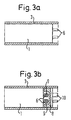
- Fig. 3a shows a sectional view of an inventive Sensor, the cut parallel to the plane of the drawing runs through the central axis of the cylindrical shaped body 1.
- the molded body 1 is in the already described Way surrounded by the sleeve element 3.
- Fig. 3a In the embodiment shown in Fig. 3a are in the molded body molded connector 6 provided, which from the Protruding molded body 1 and an electrical contact enable the sensor of the invention.
- the connector 6 are used together with that in the sensor Electronics encapsulated with plastic compound to this Way to obtain the molded body 1 shown in Fig. 3a.
- the connector 8 has on its the contacts 7 facing side bushings 9, which for the manufacture an electrical contact to the connecting contacts 7 to care.
- the connector 8 On its side facing away from the sockets 9 is the connector 8 optionally provided with plug or socket elements 10, via which the sensor shown on the periphery can be connected.
- the outer contour of the connector 8 corresponds to the outer contour of the shaped body 1, so that for example the shaped body 1 from the left and the connector 8 from the right into the Sleeve element 3 inserted and in this way electrically can be connected. It is also natural also possible to join molded body 1 and connector 8, before the unit from molded body 1 and connector 8 is inserted into the sleeve element 3.
- the contacts 10 used for connection to the periphery can be adapted as desired to customer requirements, whereas the bushings 9 always have the same shape, so a uniform molded body 1 despite different contacts 10 to be able to use.
- the connector 8 in the sleeve element 3 is preferred fixed by a connection with it.
Landscapes
- Switches Operated By Changes In Physical Conditions (AREA)
- Geophysics And Detection Of Objects (AREA)
- Injection Moulding Of Plastics Or The Like (AREA)
- Measuring Oxygen Concentration In Cells (AREA)
Abstract
Description
- Fig. 1a bis 1c
- das Prinzipschaubild eines erfindungsgemäßen Sensors in drei unterschiedlichen Phasen seiner Herstellung,
- Fig. 2a bis 2c
- einen erfindungsgemäßen Formkörper in Verbindung mit unterschiedlichen Hülsenelementen, und
- Fig. 3a, 3b
- zwei unterschiedliche Möglichkeiten der Realisierung elektrischer Anschlußelemente eines erfindungsgemäßen Sensors.
Claims (11)
- Sensor, insbesondere optoelektronischer, induktiver oder magnetischer Sensor mit in einem Gehäuse angeordneten elektronischen Bauteilen und von außen zugänglichen Anschlußelementen,
dadurch gekennzeichnet,daß die elektronischen Bauteile bei weiterhin zugänglichen Anschlußelementen (6, 10) zumindest großteils mit Kunststoffmasse umspritzt sind,daß die die elektronischen Bauteile umgebende Kunststoffmasse einen festen Formkörper (1) bildet, welcher zumindest teilweise in ein Hülsenelement (3-5) einführbar ist, unddaß Mittel (2) zur Fixierung der relativen Position zwischen Formkörper (1) und Hülsenelement (3-5) vorgesehen sind. - Sensor nach Anspruch 1, dadurch gekennzeichnet, daß der Formkörper (1) mit Vertiefungen (2) versehen ist, in die benachbart zu diesen Vertiefungen (2) gelegene Bereiche des Hülsenelements (3) eingedrückt sind, um so Formkörper (1) und Hülsenelement (3) gegeneinander zu fixieren, wobie insbesondere die Vertiefungen (2) die Form zumindest einer Nut, insbesondere einer Ringnut aufweisen.
- Sensor nach Anspruch 2, dadurch gekennzeichnet, daß das Hülsenelement (3) in seinen benachbart zu einer oder mehreren Ringnuten gelegenen Bereichen gebördelt ist.
- Sensor nach einem der vorhergehenden Ansprüche, dadurch gekennzeichnet, daß das Hülsenelement (3-5) an einer oder an mehreren Stellen am Formkörper (1) fixiert und insbesondere vollflächig mit diesem verbunden ist, und/oder daß das Hülsenelement (3-5) auf den Formkörper (1) aufgeschrumpft oder aufgeschraubt ist.
- Sensor nach einem der vorhergehenden Ansprüche, dadurch gekennzeichnet, daß das Hülsenelement (3-5) auf seiner Innenseite mit einem Gewinde, insbesondere mit einem selbstschneidenden Gewinde zur Erzeugung eines Gewindes auf der Außenseite des Formkörpers (1) versehen ist, und/oder daß Hülsenelement (3-5) und Formkörper (1) miteinander verklebt und/oder verpreßt sind, und/oder daß der Formkörper (1) mit dem Hülsenelement (3-5) galvanisch überzogen ist.
- Sensor nach einem der vorhergehenden Ansprüche, dadurch gekennzeichnet, daß das Hülsenelement (3-5) im wesentlichen eine hohlzylindrische Form aufweist, und/oder daß die Außenkontur des Hülsenelements (3-5) eine quadratische oder rechteckige Form aufweist.
- Sensor nach einem der vorhergehenden Ansprüche, dadurch gekennzeichnet, daß das Hülsenelement (3-5) die ihm zugewandte Außenseite des Formkörpers (1) teilweise oder vollständig bedeckt, und/oder daß das Hülsenelement (3-5) aus Metall oder Kunststoff besteht, und/oder daß die Außenseite des Hülsenelements (3-5) im wesentlichen glatt ausgebildet oder mit einem Gewinde versehen ist.
- Sensor nach einem der vorhergehenden Ansprüche, dadurch gekennzeichnet, daß der Formkörper (1) in Hülsenelementen (3-5) unterschiedlicher Abmessungen fixierbar ist, und/oder daß der Formkörper (1) in unterschiedlichen hohlzylindrischen Hülsenelementen (3-5) mit jeweils gleichem, dem Außenumfang des Formkörpers (1) entsprechenden Innenumfang und mit unterschiedlichem Außenumfang bzw. unterschiedlicher Außenkontur fixierbar ist.
- Sensor nach einem der vorhergehenden Ansprüche, dadurch gekennzeichnet, daß im Formkörper (1) ein umspritzter Anschlußstecker vorhanden ist, oder daß im Formkörper (1) umspritzte Anschlußkontakte (7) zur nachträglichen Kopplung mit einem an die jeweiligen Anforderungen anpassbaren Anschlußstecker (8) vorhanden sind.
- Sensor nach Anspruch 9, dadurch gekennzeichnet, daß der nachträglich angekoppelte Anschlußstecker (8) zumindest bereichsweise vom Hülsenelement (3) umgeben und bevorzugt mit diesem verbunden und auf diese Weise fixiert ist.
- Verfahren zur Herstellung eines Sensors nach einem der vorhergehenden Ansprüche,
dadurch gekennzeichnet,daß zuerst das Formteil (1) und das Hülsenelement (3-5) als zwei voneinander unabhängige Bauteile hergestellt werden und anschließend das Formteil (1) in das Hülsenelement (3-5) eingeführt und in diesem fixiert wird.
Applications Claiming Priority (2)
| Application Number | Priority Date | Filing Date | Title |
|---|---|---|---|
| DE1997101788 DE19701788A1 (de) | 1997-01-20 | 1997-01-20 | Sensor mit Gehäuse |
| DE19701788 | 1997-01-20 |
Publications (2)
| Publication Number | Publication Date |
|---|---|
| EP0854576A2 true EP0854576A2 (de) | 1998-07-22 |
| EP0854576A3 EP0854576A3 (de) | 1998-09-09 |
Family
ID=7817812
Family Applications (1)
| Application Number | Title | Priority Date | Filing Date |
|---|---|---|---|
| EP97118072A Withdrawn EP0854576A3 (de) | 1997-01-20 | 1997-10-17 | Sensor mit Gehäuse |
Country Status (2)
| Country | Link |
|---|---|
| EP (1) | EP0854576A3 (de) |
| DE (1) | DE19701788A1 (de) |
Families Citing this family (2)
| Publication number | Priority date | Publication date | Assignee | Title |
|---|---|---|---|---|
| DE102008037667B4 (de) | 2008-08-14 | 2020-06-04 | Asm Automation Sensorik Messtechnik Gmbh | Verfahren zum Einbetten und Schützen von elektronischen Schaltungen sowie danach hergestelltes elektronisches Bauteil |
| DE102016211004A1 (de) | 2016-06-21 | 2017-12-21 | Zf Friedrichshafen Ag | Verfahren zur Herstellung eines Sensorsystems mit zwei induktiven Sensoren |
Family Cites Families (9)
| Publication number | Priority date | Publication date | Assignee | Title |
|---|---|---|---|---|
| DE3247336A1 (de) * | 1982-12-21 | 1984-06-28 | Rudolf 7896 Wutöschingen Klaschka | Bechergehaeuse und verschlussverfahren |
| DE3545961A1 (de) * | 1985-12-23 | 1987-06-25 | Beru Werk Ruprecht Gmbh Co A | Sensorvorrichtung |
| DE3833967A1 (de) * | 1988-10-06 | 1990-04-12 | Hiss Eckart | Messgehaeuse |
| DE4023792C2 (de) * | 1990-07-26 | 2000-05-11 | Siemens Ag | Verfahren zur Herstellung eines Näherungsschalters mit Befestigungshülse |
| DE4323084A1 (de) * | 1993-07-10 | 1995-01-12 | Vdo Schindling | Induktiver Drehzahlgeber und Verfahren zu seiner Herstellung |
| DE4332541A1 (de) * | 1993-09-24 | 1995-03-30 | Bosch Gmbh Robert | Flüssigkeitsdichte Gehäuse für elektrische Komponenten und Verfahren zu dessen Herstellung |
| DE4340177A1 (de) * | 1993-11-25 | 1995-06-01 | Mannesmann Kienzle Gmbh | Meßwertgeber |
| DE4438763A1 (de) * | 1994-10-29 | 1996-05-02 | Vdo Schindling | Sensor mit einem topfförmigen Sensorgehäuse |
| DE19521361A1 (de) * | 1995-06-12 | 1996-12-19 | Siemens Ag | Elektrisches Schaltgerät |
-
1997
- 1997-01-20 DE DE1997101788 patent/DE19701788A1/de not_active Withdrawn
- 1997-10-17 EP EP97118072A patent/EP0854576A3/de not_active Withdrawn
Also Published As
| Publication number | Publication date |
|---|---|
| DE19701788A1 (de) | 1998-07-30 |
| EP0854576A3 (de) | 1998-09-09 |
Similar Documents
| Publication | Publication Date | Title |
|---|---|---|
| DE19608675C2 (de) | Temperaturmeßvorrichtung mit einer medienführenden Rohrleitung | |
| DE2645034C2 (de) | Zündelektrode für Brenner | |
| CH622870A5 (de) | ||
| DE3539449A1 (de) | Verbindung von leichtmetallprofilen mit anschlusselementen | |
| DE2845308C3 (de) | Fitting oder dergleichen aus formstabilem Kunststoff für Rohrverbindungen sowie Verfahren und Werkzeug zu seiner Herstellung | |
| DE3105217C2 (de) | Befestigungsvorrichtung an lösbar miteinander verbindbaren Beschlag- oder Ausstattungsteilen und Verfahren zur Herstellung derselben | |
| DE2147188A1 (de) | Geformtes rohrstueck mit einem gekruemmten und mindestens einem geraden abschnitt, und formteil zu dessen herstellung | |
| DE4310125C2 (de) | Muffe und Verfahren zu ihrer Herstellung | |
| EP1318565B1 (de) | Antenne, insbesondere Mobilfunkantenne, mit einer Zentrierhilfe bei ihrer Herstellung | |
| EP0854576A2 (de) | Sensor mit Gehäuse | |
| DE29724696U1 (de) | Sensor mit Gehäuse | |
| DE19740551A1 (de) | Gleichstromelektromotor | |
| DE4224618C2 (de) | Verfahren zum Herstellen elektrischer Steckverbinder und nach dem Verfahren hergestellte Steckverbinder | |
| EP0544071A1 (de) | Lagerachse für eine, eine Beleuchtungseinrichtung aufweisende Fahrzeugsonnenblende | |
| DE4328240A1 (de) | Verfahren zur Herstellung eines Steckers und Spritzform zur Durchführung des Verfahrens | |
| DE2850195C2 (de) | Elektrischer Isolator | |
| DE3840140C2 (de) | Steckerstift für elektrische Anschlußstecker | |
| DE4118913C1 (en) | Axle bearing for vehicle sun visor with illumination device - has extension surrounded by preform piece, both L=shaped and of plastics material | |
| DE68905488T2 (de) | Zuendkerzensteckverbindung. | |
| DE102016108311B9 (de) | Verfahren zur Herstellung einer Kabelzugentlastung und Steckverbinder mit dieser Kabelzugentlastung | |
| DE69831861T2 (de) | Wechselstromsteckereinheit | |
| DE2613236C3 (de) | Zündkerzenentstörstecker | |
| DE10217494B4 (de) | Verfahren zur Herstellung einer Zündvorrichtung für eine Brennkraftmaschine sowie Zündvorrichtung | |
| DE2531765C3 (de) | Vorrichtung zum Spritzen des Griffkörpers für elektrische Steckverbinder | |
| DE2740232C3 (de) | Verbindungsmuffe |
Legal Events
| Date | Code | Title | Description |
|---|---|---|---|
| PUAI | Public reference made under article 153(3) epc to a published international application that has entered the european phase |
Free format text: ORIGINAL CODE: 0009012 |
|
| AK | Designated contracting states |
Kind code of ref document: A2 Designated state(s): CH DE DK FR IT LI |
|
| PUAL | Search report despatched |
Free format text: ORIGINAL CODE: 0009013 |
|
| AK | Designated contracting states |
Kind code of ref document: A3 Designated state(s): AT BE CH DE DK ES FI FR GB GR IE IT LI LU MC NL PT SE |
|
| AKX | Designation fees paid | ||
| RBV | Designated contracting states (corrected) | ||
| 17P | Request for examination filed |
Effective date: 19990309 |
|
| RBV | Designated contracting states (corrected) |
Designated state(s): CH DE DK FR IT LI |
|
| 17Q | First examination report despatched |
Effective date: 20020318 |
|
| STAA | Information on the status of an ep patent application or granted ep patent |
Free format text: STATUS: THE APPLICATION IS DEEMED TO BE WITHDRAWN |
|
| 18D | Application deemed to be withdrawn |
Effective date: 20020730 |