EP0852328B1 - Appareil de mesure ameliorant la capacite d'adaptation et d'enlevement des tremies - Google Patents
Appareil de mesure ameliorant la capacite d'adaptation et d'enlevement des tremies Download PDFInfo
- Publication number
- EP0852328B1 EP0852328B1 EP97924360A EP97924360A EP0852328B1 EP 0852328 B1 EP0852328 B1 EP 0852328B1 EP 97924360 A EP97924360 A EP 97924360A EP 97924360 A EP97924360 A EP 97924360A EP 0852328 B1 EP0852328 B1 EP 0852328B1
- Authority
- EP
- European Patent Office
- Prior art keywords
- hopper
- gate
- weighing
- operating member
- hoppers
- Prior art date
- Legal status (The legal status is an assumption and is not a legal conclusion. Google has not performed a legal analysis and makes no representation as to the accuracy of the status listed.)
- Expired - Lifetime
Links
Images


Classifications
-
- G—PHYSICS
- G01—MEASURING; TESTING
- G01G—WEIGHING
- G01G19/00—Weighing apparatus or methods adapted for special purposes not provided for in the preceding groups
- G01G19/387—Weighing apparatus or methods adapted for special purposes not provided for in the preceding groups for combinatorial weighing, i.e. selecting a combination of articles whose total weight or number is closest to a desired value
- G01G19/393—Weighing apparatus or methods adapted for special purposes not provided for in the preceding groups for combinatorial weighing, i.e. selecting a combination of articles whose total weight or number is closest to a desired value using two or more weighing units
-
- G—PHYSICS
- G01—MEASURING; TESTING
- G01G—WEIGHING
- G01G21/00—Details of weighing apparatus
- G01G21/22—Weigh pans or other weighing receptacles; Weighing platforms
Definitions
- the present invention relates to a weighing apparatus wherein hoppers for receiving and discharging articles to be weighed can easily detachably mounted on the body of the weighing apparatus.
- a combinational weighing apparatus generally used for automatically weighing, for example, various articles is provided with a plurality of weighing hoppers and is so configured as to perform a weighing of the articles which have been dispersedly supplied onto those weighing hoppers, as to perform a combinational calculatiion based on the weights measured by those weighing hoppers, as to subsequently determine a combination of combined sums which may fall within a permissible range with respect to a target weight, and as to discharge the articles only from one of the weighing hoppers which has given the combination so that an aggregation of the articles of a total weight falling within the permissible range.
- This type of weighing appratus may have a pool hopper disposed immediately above each of the weighing hoppers so that when the articles to be weighed are discharged from the weighing hoppers, articles to be weighed, which participate in the subsequent combination, can be immediately discharged from the pool hoppers onto the weighing hoppers.
- this type of weighing apparatus is provided with a plurality of hoppers and, in such case, a hopper generally called a gated-type hopper is employed for each hopper.
- This gated-type hopper comprises, for example, a hopper body having a top opening upwardly and a bottom formed with a discharge port, and a gate for selectively opening and closing the discharge port at said bottom and is so configured that articles to be weighed which have been supplied through the top opening of the hopper body can be discharged from the bottom discharge port by selectively opening and closing the gate.
- the Japanese Examined Utility Model Publication No. 7-6502 discloses the structure comprising a motor as a drive source, a cam mounted on a rotary shaft of the motor, an operating lever protruding outwardly from a side surface of the body of the weighing apparatus and drivingly associated with rotation of the cam so as to undergo a rocking motion, all provided on the side of the weighing apparatus, and a link member provided on the side of the hopper and connected with a gate.
- This hopper is fitted to the body of the weighing apparatus with the operating lever engaged with the link member so that the link member can be operated in response to the rocking motion of the operating lever to thereby selectively open and close the gate of the hopper.
- the Japanese Laid-open Utility Model Publication No. 6-58328 discloses the structure in which there is provided a push rod capable of being selectively advanced and retracted from the side of the body of the weighing apparatus so that a link member provided on the side of the hopper and connected with the gate can be operated by this push rod to selectively open and close the gate.
- US-A-5324894 discloses a similar device.
- the present invention has been devised to substantially eliminate the above discussed problems and is intended to provide a weighing apparatus wherein the structure of the hopper is simplified to thereby improve the workability in detachment relative to the body of the weighing apparatus, the maintenance and the cleanness, and wherein a mechanism for inhibiting the opening of the gate during closure of the gate is realized in a drive device on the side of the body of the weighing apparatus with a simple structure.
- a weighing apparatus comprises a hopper including a hopper body having an upper portion opening and a lower portion provided with a discharge opening and a gate drivingly provided in the hopper body for selectively opening and closing the discharge opening, and an apparatus body on which the hopper are detachably mounted, a drive device being provided on the apparatus body B for driving the gate of the hopper to selectively open and close the discharge openings of the hopper body.
- Said drive device includes a drive source, a transmission mechanism for transmitting a driving force of the drive source, and an operating member adapted to be driven by the driving force so transmitted by the transmission mechanism, said gate of the hopper being provided with engagement portion engageable with the operating member, said gate undergoing a rocking motion together with the engagement portion by the drive of the operating member to selectively open and close the discharge opening of the hopper.
- the transmission mechanism includes a spring for applying a biasing force to the operating member to cause the latter to operate in one of opening and closing directions of the gate and a converting mechanism for converting the driving force of the drive source into a power with which the operating member can operate in the other direction against the biasing force, said transmission mechanism, when the gate close the discharge opening of the hopper, preventing the operating member from being driven by an external force from a gate side to open the discharge opening.
- the gate of the hopper in place of a link member of a complicated structure hitherto provided on the side of the hoppers and having a relatively large number of component parts, the gate of the hopper is provided with an engagement portion engageable with the operating member and rockable together with the gate, that is, an engagement portion which does not require a complicated structure such as the link member which has relatively rockable portions and, when the operating member is driven, the gate undergoes a rocking motion together with this engagement portion to thereby selectively open and close the discharge opening of the hopper and, therefore, the structure of the hopper can be simplified. As a result thereof, a job of mounting or detaching to or from the weighing apparatus body, the maintenance and the cleaning performance of the hopper can be improved.
- the discharge opening will not be opened by an external force from the gate side, the possibility of the gate being opened under the influence of the weight of the articles to be weighed which have been supplied into the hopper can be avoided to thereby eliminate the inconvenience associated with fall of some of the articles to be weighed.
- the drive source and the transmission mechanism of the drive device are covered by a casing fitted to the apparatus body and the transmission mechanism within the casing and the operating member outside the casing are connected with each other through a support shaft extending through wall of the casing.
- arrangement may be made so that the spring applies a biasing force to the converting mechanism in a direction required to operate the operating member to open the gate, so that the converting mechanism upon receipt of the driving force of the drive source operates the operating member at all times against the biasing force in a direction required to close the gate.
- the spring applies a biasing force to the converting mechanism in a direction required to operate the operating member to close the gate, so that the converting mechanism upon receipt of the driving force of the drive source operates the operating member at all times against the biasing force in a direction required to open the gate and there is provided a link member which is brought to a halt at the gate closed position past a pondering point.
- the drive device includes a single drive source, a plurality of transmission mechanisms for transmitting the driving force of the drive source independently relative to each other, and a plurality of operating members adapted to be driven by the driving forces transmitted from the transmission mechanisms, respectively, and the hoppers are provided for each of the operating members.
- the hopper and the transmission mechanism and the operating member of the drive device are loaded, as a tare weight, on a load detecting means for detecting the weight of a load, and when the gate is in position to close the discharge opening of the hopper body, the drive source of the drive device is disengaged from the transmission mechanism.
- the hopper and the transmission mechanism and the operating member of the drive device are loaded as a tare weight on the load detecting means and the drive source will not be loaded as a tare weight and, therefore, the tare weight can be minimized to avoid increase of the load detecting means.
- the drive source which is not regarded as a tare weight and the transmission mechanism which is regarded as a tare weight are separated from each other, wherefore an external disturbance resulting from operation of the drive source will not be transmitted to the load detecting means to thereby ensure a high weighing accuracy with the tare weight fixed.
- a first casing for covering the drive source, the first transmission mechanism and a portion of the second transmission mechanism is mounted on the apparatus body and a second casing for covering the other portion of the second transmission mechanism is mounted on the first casing.
- the present invention can be applied to a combinational weighing apparatus.
- the combinational weighing apparatus includes a plurality of weighing hoppers, a pool hopper for supplying articles to be weighed onto each of the weighing hoppers, and a load detecting means for detecting the weight of the articles within the weighing hoppers and operates to perform a combinational calculation of weights of the articles within the weighing hoppers to select a combination of the weighing hoppers which give combined sums which fall within a permissible range.
- one of the pool hoppers and one of the weighing hoppers positioned immediately below such one of the pool hoppers forms a pair of hopper and that the drive device includes, for the pair of the hoppers, a drive source, a plurality of transmission mechanisms for transmitting driving forces of the drive source independently relative to each other, and a plurality of operating members adapted to be driven by the driving force so transmitted by the transmission mechanisms to selectively open and close the gates of the hoppers.
- the single drive source it is possible to upper and lower pairs of pool hoppers and weighing hoppers having different opening or closing timings can be handled with the same and single drive source.
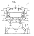
- Fig. 1 is a schematic front elevational view of a weighing apparatus according to the present invention and, more particularly, the entire structure of a combinational weighing apparatus 1 of an automatic weighing type and a body B of this weighing apparatus includes a frame 2, a base 3, support legs 4 and a support table 5, wherein said base 3 having an opening 3a defined at a central portion thereof is mounted on the frame 2 and the support table 5 is supported on the base 3 through the support legs 4 ⁇ 4.
- a dispensing table 6 of a vibratory type and a plurality of troughs 7 ⁇ 7 of a vibratory type disposed radially around the dispensing table 6 are provided on a top surface of the support table 5, and a plurality of hopper pairs including upper and lower paired pool hoppers 8 and weighing hoppers 9 are provided around the support table 5, that is, adjacent the outer periphery of the body B in alignment with the respective troughs 7.
- a ring member 10 is fitted to the support legs 4 by means of a plurality of brackets 4a secured to the respective support legs 4, and individual chutes 11 ⁇ 11 equal in number to the number of the weighing hoppers 9 are engaged to corresponding hooks 11a ⁇ 11a at respective locations below the weighing hoppers 9 to thereby form a collective chute as a whole.
- a funnel-shaped discharge chute 12 is positioned below the individual chutes 11 by means of associated fixtures (not shown).
- a combinational calculation means incorporated in the control unit 15 performs a combinational calculation of the weights of the articles to be weighed within the weighing hoppers to determine a combination of combined sums which may fall within a permissible range with respect to a target weight, and then discharges the articles only from the weighing hoppers 9 which have given the combination.
- the articles so discharged are collectively discharged from a discharge port 12a at a lower end of the discharge chute 12 through the individual chutes 11 and the associated discharge chutes 12.
- each individual chutes 11 has its lower end mounted on an upper edge of the discharge chute 12 and pivots about a fulcrum, which is defined by a point of engagement between the ring member 10 and the associated hook 11a, in response to change of the fitting position of the discharge chute 12 in a vertical direction, so that the angle of inclination thereof can be changed freely.
- a fulcrum which is defined by a point of engagement between the ring member 10 and the associated hook 11a
- each of the pool hoppers 8 and the weighing hoppers 9 used in this weighing apparatus 1 is of a gated-type hopper including a horizontally polygonally sectioned hopper body 21, 31 having an upper opening 21a, 31a and a lower discharge opening 21b, 31b, and a gate 22, 32 for selectively opening or closing the lower discharge opening 21b, 31b of the hopper body 21, 31.
- Pairs of mounting brackets 23, 23; 33, 33 for mounting the hopper bodies 21, 31 on the support table 5 are, although only an upper front member thereof is shown in the drawing, provided in the hopper bodies 21, 31 in face-to-face relation with each other whereas the gates 22, 32 referred to above are provided with connecting brackets 24, 34 for connecting the gates 22, 32 with the respective hopper bodies 21, 31. And, these connecting brackets 24, 34 are mounted on the respective hopper bodies 21, 31 through the mounting brackets 23, 33 for rotation about support shafts 25, 35, and the gates 22, 32 can selectively open and close the lower discharge openings 21b, 31b of the hopper bodies 21, 31 when the connecting brackets 24, 34 are rotated about the support shafts 25, 35 in respective directions shown by the arrows a and b.
- a peripheral surface of the support table 5 is provided with upper and lower casings 41 and 61 of each hopper unit 40 as will be described later, and pairs of support brackets 42, 42; 62, 62 formed to a predetermined shape are, although only one member of each pair is shown in the drawing, provided in the casings 41, 61 in face-to-face relation with each other and a bolt 42a is embedded in a position generally intermediate between the support brackets 42, 42 of the upper casing 41 (See Fig. 3).
- upper and lower shaft members 26, 27; 36, 37 extend between the mounting brackets 23, 23; 33, 33 of each of the pool hoppers 8 and the weighing hoppers 9, and of them the three shaft members 26, 36 and 37 are engaged to the support brackets 42, 62 and the shaft member 27 is held in abutment with ahead of the bolt 42a wherefore the pool hoppers 8 and the weighing hoppers 9 are detachably mounted on the support table 5 through the first and second casings 41, 61 positioned one above the other.
- extensions 24a, 34a are formed on front sides of the connecting brackets 24 of the gates 22 of the pool hoppers 8 and opposite sides of the connecting brackets 34 of the gates 32 of the weighing hoppers 9,respectively, and rollers 28, 38, which serve as engaging portions, are rotatably provided on those extensions 24a, 34a.
- operating arms 44, 64 capable of being rocked about support shafts 43, 63, respectively, are similarly provided on front sides of the first (upper) casings 41 and opposite sides of the second (lower) casings 61, respectively, with their tip portions engaging the rollers 28, 38 to hold them.
- the gates 22, 32 can undergo a rocking motion together with the rollers 28, 38 in the directions a and b through engagement between the operating arms 44, 64 and the rollers 28, 38, to thereby cause the lower discharge openings 21b, 31b of the hopper bodies 21, 31 to be selectively opened and closed.
- the arrows a and b, the arrows c and d and arrows e and f as will be mentioned later are for the purpose of illustration of the direction of rocking and are not used to show the range of rocking.
- Figs. 3 and 4 are longitudinal sectional views in which of the hopper units 40 the upper operating arms 44 for selectively opening and closing the pool hoppers 8 or the lower operating arms 64 for selectively opening and closing the weighing hoppers 9 and their associated drive mechanisms are mainly shown.
- the hopper units 40 includes a drive device D having a drive source 95, a transmission mechanism T1, T2 as will be described later and the above described operating arms 44, 64, the above described casings 41, 61 and the hoppers 8, 9.
- the upper casings 41 are of a shape having an upper portion bulged outwardly and a lower portion formed into an inclined surface, and are fixed to the support table 5 by means of a plurality of bolts 91 through peripheral flanges, and base members 92 are secured to the inner peripheral surface of a lower flange portion so as to extend generally vertically therefrom, with said base members 92, although not shown in detail, further fixed to mounting frames 41a for connecting them with the upper casings 41.
- a motor housing 93 is fitted to an inner surface of the outwardly bulged upper portion by means of a bolt 94 with a drive motor 95 accommodated inside the housing 93.
- a drive force of this drive motor 95 is transmitted to the operating arms 44, 64 through first and second transmission mechanisms T1 and T2 in a manner as will subsequently be described.
- the drive motor 95 and base end portions of the first and second transmission mechanisms T1 and T2 on one side adjacent the drive motor 95 are covered by the upper casing 41 while a tip portion of the second transmission mechanism T2 on one side adjacent the operating arm 64 is covered by the lower casing 61.
- a rotary shaft 96 of the drive motor 95 extends in a direction towards opposite ends thereof as shown in a plan view of Fig. 5 with first and second cams 45 and 65 of a predetermined profile being coupled therewith.
- a shaft support member 97 is formed so as to extend upwardly from the inner surface of the previously described bulged portion of the upper casing 41, and the support shaft 43 is rotatably supported by this support member 97 and a front wall surface of the casing 41 not shown in Fig. 3.
- the upper operating arm 44 is fixed to an outwardly extended end of the support shaft 43 by means of, for example, a pin and a block body 47 including a cam follower 46 movable along the first cam 45 is similarly fixed to the support shaft 43 within the casing 41.
- the transmission mechanism T1 within the casing 41 and the operating arm 44 positioned outside the casing 41 are connected with each other through the support shaft 43 which is supported having extended through the wall of the casing 41.
- a bracket 49 formed with a pin 48 so as to extend outwardly therefrom is fitted to the block body 47, a spring 51 is suspended between this pin 48 and a pin 50 formed on the base member 92 so as to extend outwardly therefrom, and by this spring 51 the block body 47 and the operating arm 44 are biased at all times in a direction shown by the arrow c, that is, in such a direction as to open the pool hopper 8, and at the same time, the cam follower 46 disposed on the block body 47 at a portion opposite to an engaging portion between the operating arm 44 and the roller 28 with respect to the support shaft 43 is held at all times in condition biased towards the first cam 45.
- the cam 45 rotates by the drive motor 95 and when the lift of the cam follower 46 increases, the operating arm 44 undergoes a rocking motion against the biasing force of the spring 51 in a direction shown by the arrow d, that is, in such a direction as to close the pool hopper 8. Conversely, when the lift of the cam follower 46 decreases, the operating arm 44 undergoes a rocking motion by the action of the biasing force of the spring 51 in a direction shown by the arrow c, that is, in such a direction as to open the pool hopper 8.
- the transmission T1 converts a rotary drive force of the drive motor 95 into an operation to cause the operating arm 44 to be rocked in the gate closing direction against the biasing force by means of a converting mechanism U including the cam 45 and the block body 47.
- a converting mechanism U including the cam 45 and the block body 47.
- This operating arm 64 is operable to selectively open and close the weighing hopper 9 by which the weight of the articles to be weighed can be measured, and a load cell 66 which serves as a load detector for weighing the weight of the articles to be weighed has one end fixed to the base member 92 by means of bolts 67.
- a support body 68 for supporting a link member 72 (Fig. 4) associated with a lower operating arm 64 as will be described subsequently is similarly fixed to a movable end portion, which is the opposite end of the load cell 66, by means of bolts not shown, and the support body 68 is fixed to a lower casing 61.
- a round opening 41b is formed in a lower inclined surface of the upper casing 41, through which opening 41b the lower casing 61 is fitted to the support body 68, and a diaphragm 69 for closing the opening 41b is sandwiched at a joint surface thereof.
- the diaphragm 69 is of a type wherein, as shown in Fig. 6 on an enlarged scale, a ring portion 69a is integrally formed with a peripheral edge thereof and a core 69b is incorporated in the ring portion 69a, and is assembled in the upper casing 41 without using any screws and nuts, but merely pressure-fitting into the opening 41b.
- a support shaft 70 is provided on an upper end portion of the support body 68 fitted to the load cell 66 of Fig. 4 and a first link member 72 having a cam follower 71 movable along the second cam 65 is rotatably supported on the support shaft 70, and a spring 75 is interposed between a pin 73, provided on the first link member 72, and a pin 74 provided on the support body 68, to urge at all times the cam follower 71 in a direction towards the second cam 65.
- a lower end of the first link member 72 has a second link member 76 connected thereto for rotation about a support shaft 77.
- a shaft support member 78 is formed inside the lower casing 61 so as to protrude outwardly, and the support shaft 63 is rotatably supported by this support member 78 and an opposite wall surface of the casing 61 in Fig. 4.
- the lower operating arm 64 is fixed to an outwardly protruding end of the support shaft 63, and a block body 80 rotatably connected with the second link member 76 by means of a support shaft 79 is similarly fixed to the support shaft 63 within the casing 61.
- a tip end portion of the transmission mechanism T2 within the casing 61 and the operating arrn 64 outside the casing 61 are connected with each other through the support shaft 63 which is supported having extended through the wall of the casing 61.
- the block body 80 is fitted with a bracket 82 having a pin 81 provided thereon so as to project outwardly therefrom, a spring 84 being interposed between this pin 81 and a pin 83, provided inside the casing 61, so that a biasing force of the spring 84 can be applied to the block body 80 and the operating arm 64 to urge the both about the support shaft 63 in a direction shown by the arrow d, that is, in such a direction as to close the weighing hopper 9.
- the transmission mechanism T2 converts a rotary drive force of the drive motor 95 through the converting mechanism U2 including the cam 65, the link members 72 and 76, the block body 80 and so on, into an operation for rocking the operating arm 64 in a gate opening direction against the biasing forces.
- the weighing hopper 9 In this way, at the time while the weighing hopper 9 is in an opened condition the articles to be weighed which have been supplied into the hopper 9 are measured, only the support body 68, the lower casing 61 fitted to the support body 68 and link members 72 and 76 and the operating arm 64 provided therein, the weighing hopper 9 fitted through the support brackets 62 and so on are loaded on the load cell 66 as a tare weight. Accordingly, the weighing accuracy can be secured without being adversely affected by an external factor brought about by the contact between the cam follower 71 and the cam 65, that is, an external factor resulting from an operation of the drive motor 95.
- the operating arm 64 is prevented from being rocked in the direction of the arrow c and the gate 32 of the weighing hopper 9 is locked and, therefore, there is no possibility of the gate 32 being opened and the problem associated with fall of the articles to be weighed can be avoided.
- the pool hopper 8 and the weighing hopper 9 in the weighing apparatus 1 are not provided with such link members for selectively opening and closing the gates 22 and 32 and such biasing springs for biasing the gates in the closing direction as required in the prior art, and are detachably mounted on the support table 5. Accordingly, when the hoppers 8 and 9 are removed from the support table 5, a simple structure can be obtained in which the gates 22 and 32 are freely fitted to the hopper bodies 21 and 31 through the support shafts 25 and 35 and not only can a detaching job be performed easily, but also a routine inspection and a routine cleaning can also be performed easily. Furthermore, the drive motor 95 and the transmission mechanisms T1 and T2 of the drive device D are covered by the casings 41 and 61 and are therefore protected from water and dusts.
- the first link member 72 rockable in the directions of the arrows e and f by the cam 65 and the cam follower 71 is connected with and spaced a distance from the block body 80 and the lower operating arm 64 through the long second link member 76 and, therefore, a rocking inertia force brought about by those members 80, 64 can be increased. Accordingly, even when the drive motor 95 is rotated particularly at a high speed, it is important that the cam follower 71 can be biased at all times towards the cam 65 against such a relatively large inertia force. In view of this, in the illustrated embodiment, the use has been made of the two springs 75 and 84 to assuredly permit the cam follower 71 to follow the cam 65, to thereby avoid any possible delay in closing of the weighing hopper 9.
- the support brackets 42 and 62 fitted to the respective upper and lower casings 41 and 61 are, as shown in Fig. 2, supported at one point by means of fastening of, for example, bolts 100 ⁇ 100 with its inclination being adjustable.
- the shaft member 27 of the pool hopper 8 is engaged with the head of the bolt 42a embedded in the upper casing 41, the position of the above described head can be changed by adjusting the amount to which the bolt 42a is embedded.
- the height and the relation in arrangement of the pool hopper 8 or the weighing hopper 9 detachably engaged to the support brackets 42 and 62 can be adjusted.
- the first and second cams 45 and 65 are arranged on the rotary shaft 96 so that during one complete rotation of the drive motor 95, the pool hopper 8 and the weighing hopper 9 can be opened. In such case, during rotation of the drive motor 95 through an angle of 0 to 240° the weighing hopper 9 is opened, followed by opening of the pool hopper 8 during rotation of the drive motor 95 through an angle of 120 to 360°.
- the present invention is applicable equally not only to a combinational weighing apparatus provided with the plural weighing hoppers, but also to a weighing apparatus provided with one or a plurality of hoppers and capable of weighing the articles within the hoppers individually without combination calculation.
Landscapes
- Physics & Mathematics (AREA)
- General Physics & Mathematics (AREA)
- Weight Measurement For Supplying Or Discharging Of Specified Amounts Of Material (AREA)
Claims (10)
- Appareil de pesage comprenant une trémie (8, 9) comportant un corps (21, 31) de trémie ayant une ouverture de partie supérieure et une partie inférieure munie d'une ouverture de décharge (21b, 31b) et d'une porte (22, 32) prévue de manière entraínée dans le corps (21, 31) de trémie pour ouvrir et fermer sélectivement l'ouverture de décharge (21b, 31b) et un corps d'appareil (B) sur lequel est montée la trémie (8, 9) de manière détachable,
un dispositif d'entraínement (D) étant prévu sur le corps d'appareil (B) pour entraíner la porte (22, 32) de la trémie (8, 9) pour ouvrir et fermer sélectivement l'ouverture de décharge (21b, 31b) du corps (21, 31) de trémie,
ledit dispositif d'entraínement (D) comportant une source d'entraínement (95), un mécanisme de transmission (T1, T2) pour transmettre une force d'entraínement de la source d'entraínement (95), et un élément d'actionnement (44, 64) adapté pour être entraíné par 1a force d'entraínement transmise par le mécanisme de transmission (T1, T2), caractérisé par le fait que
ladite porte (22, 32) de la trémie (8, 9) est munie d'une partie d'accrochage (28, 38) pouvant être mise en prise avec l'élément d'actionnement (44, 64), ladite porte (22, 32) subissant un mouvement oscillant avec la partie d'accrochage (28, 38) par l'entraínement de l'élément d'actionnement (44, 64) pour ouvrir et fermer sélectivement l'ouverture de décharge (21b, 31b) de la trémie (21, 31), et
ledit mécanisme de transmission (T1, T2) comporte un ressort (51, 75, 84) pour appliquer une force de sollicitation à l'élément d'actionnement (44, 64) pour faire fonctionner ce dernier dans une direction parmi les directions d'ouverture et de fermeture de la porte (8, 9), et un mécanisme de conversion (U1, U2) pour convertir la force d'entraínement de la source d'entraínement (95) en une puissance avec laquelle l'élément d'actionnement (44, 64) peut fonctionner dans l'autre direction contre la force de sollicitation, ledit mécanisme de transmission (T1) et (T2), quand la porte (22, 32) ferme l'ouverture de décharge (21b, 31b) de la trémie (21, 31), empêchant l'élément d'actionnement (44, 64) d'être entraíné par une force extérieure depuis un côté de la porte pour ouvrir l'ouverture de décharge (21b, 31b). - Appareil de pesage selon la revendication 1, dans lequel la source d'entraínement (95) et le mécanisme de transmission (T1, T2) du dispositif d'entraínement (D) sont couverts par un capot (41, 61) monté sur le corps d'appareil (B) et le mécanisme de transmission (T1, T2) dans le capot et l'élément d'actionnement (44, 64) à l'extérieur du capot sont connectés l'un à l'autre au moyen d'un axe de support (43, 63) s'étendant à travers une paroi du capot (41, 61).
- Appareil de pesage selon la revendication 1, dans lequel le ressort (51) applique une force de sollicitation au mécanisme de conversion (U1) dans une direction requise pour faire fonctionner l'élément d'actionnement (44) pour fermer la porte (32) et dans lequel ledit mécanisme de conversion (U1), lorsqu'il reçoit la force d'entraínement de la source d'entraínement (95), fait fonctionner l'élément d'actionnement (44) à tous moments contre la force de sollicitation dans une direction requise pour ouvrir la porte (22), pour empêcher de ce fait l'élément d'actionnement (44) d'être actionné dans la direction d'ouverture sous l'influence d'une force extérieure sur un côté de la porte, laquelle force tend à ouvrir l'ouverture de décharge (21b).
- Appareil de pesage selon la revendication 1, dans lequel le ressort (75, 84) applique une force de sollicitation au mécanisme de conversion (U2) dans une direction requise pour faire fonctionner l'élément d'actionnement (64) pour fermer la porte (32) et dans lequel ledit mécanisme de conversion (U2), lorsqu'il reçoit la force d'entraínement de la source d'entraínement (95), fait fonctionner l'élément d'actionnement (64) à tous moments contre 1a force de sollicitation dans une direction requise pour ouvrir la porte (32), et comporte un élément de liaison (72, 76) qui s'arrête en une position de fermeture de porte au-delà d'un point de mesure grâce à quoi l'élément d'actionnement (64) est empêché d'être actionné dans la direction d'ouverture sous l'influence d'une force extérieure sur un côté de la porte (32), laquelle force tend à ouvrir l'ouverture de décharge (21b).
- Appareil de pesage selon la revendication 1, dans lequel le dispositif d'entraínement (D) comporte une source d'entraínement unique (95), une pluralité de mécanismes de transmission (T1, T2) pour transmettre la force d'entraínement de la source d'entraínement (95) indépendamment les uns des autres, et une pluralité d'éléments d'actionnement (44, 64) adaptés pour être entraínés par les forces d'entraínement transmises par les mécanismes de transmission (T1) et (T2), respectivement, et dans lequel la trémie (8, 9) est prévue pour chacun des éléments d'actionnement (44, 64).
- Appareil de pesage selon la revendication 1, dans lequel la trémie (9) et le mécanisme de transmission (T2) et l'élément d'actionnement (64) du dispositif d'entraínement (D) sont chargés, en tant que tare, sur un moyen de détection (66) de charge pour détecter le poids d'une charge, et dans lequel lorsque la porte (32) est en position pour fermer l'ouverture de décharge (31b) du corps (31) de trémie, la source d'entraínement (95) du dispositif d'entraínement (D) est débrayée du mécanisme de transmission (T2).
- Appareil de pesage selon la revendication 5, dans lequel un premier capot (41) pour couvrir la source d'entraínement (95), le premier mécanisme de transmission (T1) et une partie du deuxième mécanisme de transmission (T2) est monté sur le corps d'appareil (B) et un deuxième capot (61) pour couvrir l'autre partie du deuxième mécanisme de transmission (T2) est monté sur le premier capot (41).
- Appareil de pesage selon la revendication 2, dans lequel le corps (21, 31) de trémie est supporté à l'intérieur du capot (41, 61).
- Appareil de pesage selon la revendication 1, qui est un appareil de calcul combinatoire comprenant une pluralité de trémies de pesage (9), une trémie de stockage (8) pour fournir des articles à peser sur chacune des trémies de pesage (9), et un moyen de détection (66) de charge pour détecter le poids des articles situés dans les trémies de pesage (9) et capable d'effectuer un calcul combinatoire des poids des articles situés dans les trémies de pesage (9) pour choisir une combinaison des trémies de pesage (9) qui donnent des sommes combinées qui tombent dans une plage acceptable.
- Appareil de pesage selon la revendication 9, dans lequel l'une des trémies de stockage (8) et la trémie de pesage (9) positionnée immédiatement en dessous de cette trémie de stockage (8) forment une paire de trémies et dans lequel le dispositif d'entraínement (D) comprend, pour la paire de trémies (8, 9), une source d'entraínement (95), une pluralité de mécanismes de transmission (T1, T2) pour transmettre les forces d'entraínement de la source d'entraínement (95) indépendamment les unes des autres, et une pluralité d'éléments d'actionnement (44, 64) adaptés pour être entraínés par la force d'entraínement ainsi transmise par les mécanismes de transmission (T1, T2) pour ouvrir et fermer sélectivement les portes (22, 32) des trémies (8, 9).
Applications Claiming Priority (4)
| Application Number | Priority Date | Filing Date | Title |
|---|---|---|---|
| JP193964/96 | 1996-07-03 | ||
| JP19396496 | 1996-07-03 | ||
| JP19396496 | 1996-07-03 | ||
| PCT/JP1997/001968 WO1998001727A1 (fr) | 1996-07-03 | 1997-06-06 | Appareil de mesure ameliorant la capacite d'adaptation et d'enlevement des tremies |
Publications (3)
| Publication Number | Publication Date |
|---|---|
| EP0852328A1 EP0852328A1 (fr) | 1998-07-08 |
| EP0852328A4 EP0852328A4 (fr) | 2000-04-05 |
| EP0852328B1 true EP0852328B1 (fr) | 2003-08-13 |
Family
ID=16316701
Family Applications (1)
| Application Number | Title | Priority Date | Filing Date |
|---|---|---|---|
| EP97924360A Expired - Lifetime EP0852328B1 (fr) | 1996-07-03 | 1997-06-06 | Appareil de mesure ameliorant la capacite d'adaptation et d'enlevement des tremies |
Country Status (5)
| Country | Link |
|---|---|
| US (1) | US6188029B1 (fr) |
| EP (1) | EP0852328B1 (fr) |
| JP (1) | JP3670295B2 (fr) |
| DE (1) | DE69724088T2 (fr) |
| WO (1) | WO1998001727A1 (fr) |
Families Citing this family (27)
| Publication number | Priority date | Publication date | Assignee | Title |
|---|---|---|---|---|
| ATE245806T1 (de) * | 1999-05-03 | 2003-08-15 | Bilwinco As | Wägeapparat |
| WO2001062637A1 (fr) * | 2000-02-28 | 2001-08-30 | Anritsu Corporation | Dispositif d'alimentation d'articles et de distribution |
| WO2001068493A1 (fr) * | 2000-03-17 | 2001-09-20 | Anritsu Corporation | Equipement de pesage par combinaison |
| US6703568B2 (en) | 2000-05-19 | 2004-03-09 | Anritsu Corporation | Combination weighing apparatus having a weighing device base, to which a plurality of weighing devices are fixed, that is directly fixed to a stand |
| DE10048416A1 (de) * | 2000-09-29 | 2002-04-11 | David Wong | Abfüllvorrichtung |
| JP4643063B2 (ja) * | 2001-07-02 | 2011-03-02 | 正俊 今中 | ホッパ装置および計量装置 |
| JP3702204B2 (ja) * | 2001-08-13 | 2005-10-05 | ホシザキ電機株式会社 | 貯氷庫の氷放出機構部 |
| JP3819330B2 (ja) * | 2002-06-26 | 2006-09-06 | 株式会社イシダ | ホッパ及びそれを備えた計量装置 |
| US7340914B2 (en) * | 2005-01-03 | 2008-03-11 | Whirlpool Corporation | Refrigerator with a water and ice dispenser having a retractable ledge |
| KR101504214B1 (ko) * | 2008-11-28 | 2015-03-19 | 엘지전자 주식회사 | 디스펜서를 구비한 냉장고 |
| US9228883B2 (en) * | 2010-09-06 | 2016-01-05 | Yamato Scale Co., Ltd. | Weighing unit and combination weigher using the same |
| CN103026187B (zh) * | 2010-10-29 | 2014-09-17 | 大和制衡株式会社 | 组合秤 |
| US9573755B2 (en) * | 2010-10-29 | 2017-02-21 | Yamato Scale Co., Ltd. | Mechanism for opening and closing hopper gate |
| ES2593756T3 (es) | 2011-04-05 | 2016-12-13 | Yamato Scale Co., Ltd. | Mecanismo para abrir y cerrar una compuerta de tolva |
| JP4895412B1 (ja) * | 2011-07-05 | 2012-03-14 | 株式会社プラスワンテクノ | 多品種秤量装置および多品種秤量装置システム構成 |
| CN103557922B (zh) * | 2013-11-12 | 2016-06-29 | 徐州徐工施维英机械有限公司 | 一种组合式安装座及具有此结构的压式传感计量装置 |
| JP6396983B2 (ja) * | 2014-09-19 | 2018-09-26 | 株式会社イシダ | 組合せ計量装置 |
| US10323977B2 (en) * | 2014-09-19 | 2019-06-18 | Ishida Co., Ltd. | Support structure for a combination weighing device |
| CN104526883B (zh) * | 2014-11-20 | 2017-02-22 | 徐州徐工施维英机械有限公司 | 添加剂计量装置、混凝土搅拌站及添加剂计量方法 |
| CN104528370A (zh) * | 2014-12-25 | 2015-04-22 | 重庆市天星寨粉葛食品有限公司 | 用于压缩木耳的传送装置 |
| JP6707759B2 (ja) * | 2016-09-20 | 2020-06-10 | 株式会社イシダ | ホッパ及び組合せ計量装置 |
| JP6993680B2 (ja) * | 2017-11-29 | 2022-01-13 | 株式会社イシダ | ホッパ及びそれを備えた組合せ計量装置 |
| CN109297578A (zh) * | 2018-11-28 | 2019-02-01 | 广东安本智能机器有限公司 | 一种带有防护结构的驱动部件及一种组合料斗 |
| JP6777357B1 (ja) * | 2019-03-13 | 2020-10-28 | 株式会社イシダ | 組合せ計量装置 |
| JP7474473B2 (ja) * | 2020-03-18 | 2024-04-25 | 株式会社イシダ | 計量機構 |
| JP2022075207A (ja) | 2020-11-06 | 2022-05-18 | 株式会社イシダ | 物品搬送装置 |
| JP2022075204A (ja) * | 2020-11-06 | 2022-05-18 | 株式会社イシダ | 組合せ計量装置 |
Family Cites Families (10)
| Publication number | Priority date | Publication date | Assignee | Title |
|---|---|---|---|---|
| JPS5972516U (ja) * | 1982-11-08 | 1984-05-17 | 株式会社石田衡器製作所 | 自動計量装置におけるホツパ開閉装置 |
| AU565443B2 (en) * | 1982-10-01 | 1987-09-17 | K.K. Ishida Koki Seisakusho | Hopper for combination weigher |
| DE3475954D1 (en) * | 1983-05-11 | 1989-02-09 | Ishida Scale Mfg Co Ltd | Hopper for use in an automatic weighing apparatus |
| JPS608843U (ja) * | 1983-06-30 | 1985-01-22 | 株式会社 寺岡精工 | 組合せ秤におけるホツパ−構造 |
| US4705125A (en) * | 1986-11-14 | 1987-11-10 | Ishida Scales Manufacturing Company, Ltd. | Method of and apparatus for controlling hopper gate motion |
| GB8705451D0 (en) * | 1987-03-09 | 1987-04-15 | Driver Southall | Combinational weighing systems |
| US5379923A (en) * | 1992-06-17 | 1995-01-10 | Eagle Packaging Corp. | Hopper for a weighing machine |
| JPH06160162A (ja) * | 1992-11-24 | 1994-06-07 | Tokihisa Masuda | 組合せ計量装置のホッパ開閉機構 |
| US5324894A (en) * | 1993-03-01 | 1994-06-28 | Industrial Technology Research Institute | Multiple weighing apparatus for mass materials with dual-acting hopper gates mechanism |
| DE19511756A1 (de) * | 1995-03-30 | 1996-10-02 | Gestra Ag | Absperrklappe mit federbelastetem Verschlußteil |
-
1997
- 1997-06-06 US US09/033,184 patent/US6188029B1/en not_active Expired - Fee Related
- 1997-06-06 WO PCT/JP1997/001968 patent/WO1998001727A1/fr active IP Right Grant
- 1997-06-06 DE DE69724088T patent/DE69724088T2/de not_active Expired - Fee Related
- 1997-06-06 EP EP97924360A patent/EP0852328B1/fr not_active Expired - Lifetime
- 1997-06-06 JP JP53608197A patent/JP3670295B2/ja not_active Expired - Fee Related
Also Published As
| Publication number | Publication date |
|---|---|
| WO1998001727A1 (fr) | 1998-01-15 |
| EP0852328A1 (fr) | 1998-07-08 |
| DE69724088T2 (de) | 2004-06-09 |
| US6188029B1 (en) | 2001-02-13 |
| EP0852328A4 (fr) | 2000-04-05 |
| DE69724088D1 (de) | 2003-09-18 |
| JP3670295B2 (ja) | 2005-07-13 |
Similar Documents
| Publication | Publication Date | Title |
|---|---|---|
| EP0852328B1 (fr) | Appareil de mesure ameliorant la capacite d'adaptation et d'enlevement des tremies | |
| US4683966A (en) | Weighing system | |
| US6703568B2 (en) | Combination weighing apparatus having a weighing device base, to which a plurality of weighing devices are fixed, that is directly fixed to a stand | |
| JPH0629044B2 (ja) | 粉体供給装置 | |
| US4134466A (en) | Weigh jet assemblies | |
| EP1228988A1 (fr) | Equipement de pesage par combinaison | |
| KR970010001B1 (ko) | 연고체 무게측정장치 | |
| EP4119471A1 (fr) | Structure d'étanchéité et bascule équipée de cette dernière | |
| EP0139104A2 (fr) | Dispositif de mesurage combinatoire | |
| US20050072603A1 (en) | Weigh deck | |
| KR20150111155A (ko) | 자동 개폐장치가 구비되는 곡물 계량장치 | |
| JP2654469B2 (ja) | 被計量体の持ち上げ機構 | |
| JP2015169580A (ja) | 組合せ秤 | |
| JP6180336B2 (ja) | ホッパ及びそれを用いた組合せ秤 | |
| US20050087372A1 (en) | Hopper and metering device comprising it | |
| US4614244A (en) | Combination measuring apparatus | |
| JPH0332987Y2 (fr) | ||
| JP4880370B2 (ja) | 組合せ秤 | |
| WO1997041410A1 (fr) | Dispositif peseur-compteur combinatoire | |
| JP5858729B2 (ja) | ホッパの開閉機構 | |
| JP2645935B2 (ja) | 柔軟固形物計量装置 | |
| JP2016020248A (ja) | ホッパ及びこれを備える組合せ秤 | |
| JP3426315B2 (ja) | 組合せ計量装置 | |
| JPH0242655Y2 (fr) | ||
| JPH1019648A (ja) | 計量装置 |
Legal Events
| Date | Code | Title | Description |
|---|---|---|---|
| PUAI | Public reference made under article 153(3) epc to a published international application that has entered the european phase |
Free format text: ORIGINAL CODE: 0009012 |
|
| AK | Designated contracting states |
Kind code of ref document: A1 Designated state(s): DE FR GB IT |
|
| 17P | Request for examination filed |
Effective date: 19980622 |
|
| A4 | Supplementary search report drawn up and despatched |
Effective date: 20000221 |
|
| AK | Designated contracting states |
Kind code of ref document: A4 Designated state(s): DE FR GB IT |
|
| RIC1 | Information provided on ipc code assigned before grant |
Free format text: 7G 01G 13/06 A, 7G 01G 19/387 B, 7B 65G 65/40 B, 7G 01G 13/16 B |
|
| GRAH | Despatch of communication of intention to grant a patent |
Free format text: ORIGINAL CODE: EPIDOS IGRA |
|
| GRAH | Despatch of communication of intention to grant a patent |
Free format text: ORIGINAL CODE: EPIDOS IGRA |
|
| GRAA | (expected) grant |
Free format text: ORIGINAL CODE: 0009210 |
|
| AK | Designated contracting states |
Designated state(s): DE FR GB IT |
|
| REG | Reference to a national code |
Ref country code: GB Ref legal event code: FG4D |
|
| REF | Corresponds to: |
Ref document number: 69724088 Country of ref document: DE Date of ref document: 20030918 Kind code of ref document: P |
|
| ET | Fr: translation filed | ||
| PLBE | No opposition filed within time limit |
Free format text: ORIGINAL CODE: 0009261 |
|
| STAA | Information on the status of an ep patent application or granted ep patent |
Free format text: STATUS: NO OPPOSITION FILED WITHIN TIME LIMIT |
|
| 26N | No opposition filed |
Effective date: 20040514 |
|
| PGFP | Annual fee paid to national office [announced via postgrant information from national office to epo] |
Ref country code: FR Payment date: 20080617 Year of fee payment: 12 |
|
| PGFP | Annual fee paid to national office [announced via postgrant information from national office to epo] |
Ref country code: IT Payment date: 20090618 Year of fee payment: 13 |
|
| PGFP | Annual fee paid to national office [announced via postgrant information from national office to epo] |
Ref country code: GB Payment date: 20090603 Year of fee payment: 13 Ref country code: DE Payment date: 20090604 Year of fee payment: 13 |
|
| REG | Reference to a national code |
Ref country code: FR Ref legal event code: ST Effective date: 20100226 |
|
| PG25 | Lapsed in a contracting state [announced via postgrant information from national office to epo] |
Ref country code: FR Free format text: LAPSE BECAUSE OF NON-PAYMENT OF DUE FEES Effective date: 20090630 |
|
| GBPC | Gb: european patent ceased through non-payment of renewal fee |
Effective date: 20100606 |
|
| PG25 | Lapsed in a contracting state [announced via postgrant information from national office to epo] |
Ref country code: IT Free format text: LAPSE BECAUSE OF NON-PAYMENT OF DUE FEES Effective date: 20100606 |
|
| PG25 | Lapsed in a contracting state [announced via postgrant information from national office to epo] |
Ref country code: DE Free format text: LAPSE BECAUSE OF NON-PAYMENT OF DUE FEES Effective date: 20110101 |
|
| PG25 | Lapsed in a contracting state [announced via postgrant information from national office to epo] |
Ref country code: GB Free format text: LAPSE BECAUSE OF NON-PAYMENT OF DUE FEES Effective date: 20100606 |