EP0851211B1 - Optical distance measuring apparatus and method - Google Patents
Optical distance measuring apparatus and method Download PDFInfo
- Publication number
- EP0851211B1 EP0851211B1 EP96830652A EP96830652A EP0851211B1 EP 0851211 B1 EP0851211 B1 EP 0851211B1 EP 96830652 A EP96830652 A EP 96830652A EP 96830652 A EP96830652 A EP 96830652A EP 0851211 B1 EP0851211 B1 EP 0851211B1
- Authority
- EP
- European Patent Office
- Prior art keywords
- values
- electrical signals
- value
- detection means
- light
- Prior art date
- Legal status (The legal status is an assumption and is not a legal conclusion. Google has not performed a legal analysis and makes no representation as to the accuracy of the status listed.)
- Expired - Lifetime
Links
Images
Classifications
-
- G—PHYSICS
- G01—MEASURING; TESTING
- G01B—MEASURING LENGTH, THICKNESS OR SIMILAR LINEAR DIMENSIONS; MEASURING ANGLES; MEASURING AREAS; MEASURING IRREGULARITIES OF SURFACES OR CONTOURS
- G01B11/00—Measuring arrangements characterised by the use of optical techniques
- G01B11/02—Measuring arrangements characterised by the use of optical techniques for measuring length, width or thickness
- G01B11/026—Measuring arrangements characterised by the use of optical techniques for measuring length, width or thickness by measuring distance between sensor and object
-
- G—PHYSICS
- G01—MEASURING; TESTING
- G01C—MEASURING DISTANCES, LEVELS OR BEARINGS; SURVEYING; NAVIGATION; GYROSCOPIC INSTRUMENTS; PHOTOGRAMMETRY OR VIDEOGRAMMETRY
- G01C3/00—Measuring distances in line of sight; Optical rangefinders
- G01C3/02—Details
- G01C3/06—Use of electric means to obtain final indication
- G01C3/08—Use of electric radiation detectors
- G01C3/085—Use of electric radiation detectors with electronic parallax measurement
-
- G—PHYSICS
- G01—MEASURING; TESTING
- G01D—MEASURING NOT SPECIALLY ADAPTED FOR A SPECIFIC VARIABLE; ARRANGEMENTS FOR MEASURING TWO OR MORE VARIABLES NOT COVERED IN A SINGLE OTHER SUBCLASS; TARIFF METERING APPARATUS; MEASURING OR TESTING NOT OTHERWISE PROVIDED FOR
- G01D5/00—Mechanical means for transferring the output of a sensing member; Means for converting the output of a sensing member to another variable where the form or nature of the sensing member does not constrain the means for converting; Transducers not specially adapted for a specific variable
- G01D5/26—Mechanical means for transferring the output of a sensing member; Means for converting the output of a sensing member to another variable where the form or nature of the sensing member does not constrain the means for converting; Transducers not specially adapted for a specific variable characterised by optical transfer means, i.e. using infrared, visible, or ultraviolet light
-
- G—PHYSICS
- G02—OPTICS
- G02B—OPTICAL ELEMENTS, SYSTEMS OR APPARATUS
- G02B7/00—Mountings, adjusting means, or light-tight connections, for optical elements
- G02B7/28—Systems for automatic generation of focusing signals
- G02B7/30—Systems for automatic generation of focusing signals using parallactic triangle with a base line
- G02B7/32—Systems for automatic generation of focusing signals using parallactic triangle with a base line using active means, e.g. light emitter
Definitions
- the present invention relates to an optical apparatus for measuring the distance of an object and also to a process for measuring the distance of an object from an optical measuring apparatus.
- Optical apparatuses capable of measuring the distance from an object are known.
- US-A-5483051 describes bar code readers equipped with several lasers each of which is suited for focusing on an object positioned at a certain distance from the measuring apparatus within a reading range.
- JP 06 042964 discloses an apparatus for measuring a distance of an object wherein the reflected light on the surface of the object is incident on a position sensor through a photodetection optical system and the output signal of the position sensor is amplified by amplification circuits and input to a judgement part which regulates the level of the output signal of a light source and the amplification degree of the amplification circuits so that the level of the input signal can be kept nearly within a prescribed range, thus accurately measuring the distance.
- JP 05 322559 discloses an apparatus for measuring the distance of an object wherein the reflected light on the surface of the object is incident on a position sensor through a light receiving optical system and the output signal of the position sensor is input to a signal processing part which serves to generate a light quantity abnormal signal when the sum of both the output signals of the position sensor is below a first threshold or above a second threshold.
- a signal processing part which serves to generate a light quantity abnormal signal when the sum of both the output signals of the position sensor is below a first threshold or above a second threshold.
- DE 3709614 discloses a process for measuring the position of a light spot on a detector's photosensitive surface by calculating quotient of sum of and difference between two currents using light source regulation.
- the current are drawn from two opposed electrodes on the detector's surface.
- the sum of the currents is held constant by regulating the light intensity .
- a counter electrode is connected to a regulator output of which controls an electrical light source so that the summation current flowing through the counter electrode is constant irrespective of the position of the movable light spot.
- the technical problem underlying the present invention is to conceive a device which would be an alternative to those of the prior art and capable of measuring with a high degree of accuracy and relative construction simplicity the distance of an object from this device.
- the present invention concerns a process for measuring the distance of an object from an optical apparatus according to the definition of claim 1.
- Measuring the distance of the object from a measuring apparatus is then performed in accordance with a process which is relatively simple and accurate and these are qualities possessed by instruments and apparatuses widely known, in the optical and automation sector.
- step d) comprises the step of comparing the sum of the electrical signals with the maximum and minimum values of the preset range of values and if the sum found is above the maximum or below the minimum value of the preset range of values, carrying out the following steps:
- the use of a digital processing block makes possible preparing a binary algorithm for seeking a S/N ratio within the preset value range. This kind of seeking ensures minimum time for reaching the sought value.
- the process of the invention comprises the step of defining a range of M values of emission and each time the sum of the electrical signals is found to be above (or below) the maximum (or minimum) value of the preset range of values, the new emission value is calculated in a range of values which is one half the previous defined range of values.
- the present invention concerns an optical apparatus for measuring the distance of an object, according to the definition of claim 4.
- a device of this type permits measuring the distance of an object by implementing a detection system, capable of converting the light signals into equivalent electrical signals, by an optical triangulation system capable of connecting univocally the distance parameter with the angle of deviation parameter between the diffused light beam collected by the second lens and the light beam directed onto the object. Since the electrical signals generated are a function of the position of incidence of the diffused light beam coming from the illuminated object, and the position being a function of the deviation angle and consequently of the distance of the object, it is possible to find at output the exact numerical value of the distance measured by means of simple mathematical processing of the electrical signals generated by the detection means.
- the first converging lens and the second converging lens are positioned side by side in accordance with a lay substantially parallel to the' supporting plane of the object. In this manner it is possible to collect through the second converging lens the greater part of the light beam emitted through the first converging lens and diffused by the illuminated object to avoid waste of power.
- the light source is positioned in a position such as to generate a light beam having its axis perpendicular to the lay of the first converging lens. In this manner it is possible to collect through the first converging lens substantially the entire light beam emitted by the light source to avoid waste of power.
- the electrical signals generated by the detection means are two electrical currents. This allows applying the following steps of processing of the electrical signals by using relatively simple and widely known instruments and systems.
- the means for adjusting the quantity of light emitted by this light source comprise a processing circuit for adjusting the quantity of light emitted by the light source depending on the quantity of incident light on the detection means.
- the electrical signals generated by the detection means and subsequently processed by the processing means will contain, superimposed on a significant signal component, a noise component linked exclusively to the type of processing and to the physical characteristics of the photosensitive element illuminated.
- the accuracy of the measuring system will then depend exclusively on the S/N (significant signal/noise) ratio and hence on the quantity of optical signal returning onto the processing means which is a function of the distance and of the reflectivity of the photosensitive object illuminated.
- the developed regulation system for the emission allows adjusting the value of the emission and optimizing the S/N ratio while holding it in a preset range of values. In this manner a certain minimum S/N value is ensured but the possibility of having an excess of received signal (caused by an increase in the reflectivity of the illuminated object as e.g. in the case of a white body positioned at a minimum distance) which would lead to saturation of the system is also avoided.
- the processing circuit capable of adjusting the light emission on the basis of the quantity of incident light is active only when the sum of the electrical signals generated does not fall within a preset value range.
- control of the S/N ratio merely involves addition of the electrical signals generated so as to have a control signal proportioned to the reflectivity of the illuminated object.
- the processing circuit comprises an analog processing and drive block comprising at least two comparators, a counter , a first transistor and a plurality of electrical resistances arranged in parallel.
- the processing circuit comprises a digital processing and drive block comprising an analog/digital converter, a Pulse Width Modulator (PWM), a low-pass filter, a switch and a second transistor all cascaded together.
- PWM Pulse Width Modulator
- the detection means include a Position Sensitive Detector (PSD).
- PSD Position Sensitive Detector
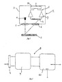
- FIGS reference number 1 shows schematically an optical apparatus for measuring the distance of an object 2.
- the apparatus 1 displays in a case 3 a light source 4.
- the light source 4 is positioned in such a manner as to generate a light beam having its axis perpendicular to the optical plane of the lens 5.
- the first lens 5 and the second lens 6 are positioned side by side in such a manner that the lens 6 collects the light beam diffused by the object 2 in a direction angularly deviated with respect to the light beam emitted by the light source 4 and directed by the first lens 5 onto the object 2.
- detection means 7 positioned above the second lens 6 in such a manner as to be able to collect at a certain point, variable depending on the measured distance, the diffused light beam penetrating the case 3 through the second lens 6.
- the detection means 7 are electrically connected to processing means 8 and convert the received light signals into two electrical signals, specifically electrical currents, of differing magnitude depending on the position of the point of incidence of the diffused light beam coming from the object.
- the detection means consist of a Position Sensitive Detector (PSD).
- the processing means 8 comprise a first amplification circuit 9 for the two electrical signals generated by the detection means 7, a successive processing circuit 10 of the amplified electrical signals and a processing and drive block 11 acting on the light source 4 in such a manner as to adjust its emission.
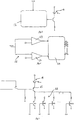
- the processing and drive block 11 can be alternatively the analog or digital type. If it is expected to use an analog processing and drive block 11 it will comprise in cascade two comparators 13, a counter with thermometer 14 with A1-AM outputs, a first transistor 15 and a plurality of electrical resistances 16 arranged in parallel (FIG 5) with in series switches M1-MM controlled by the outputs A1-AM of the counter with thermometer 14. If it is expected to use a digital processing and drive block 11 it will comprise in cascade an analog/digital converter 17, a Pulse Width Modulation (PWM) 18, a low-pass filter 19, a switch 20 and a second transistor 21 (FIG 6).
- PWM Pulse Width Modulation
- the optical apparatus 1 operates in the manner described below.
- the object 2 of which it is desired to measure the distance is before the apparatus 1 in front of the first converging lens 5.
- the light beam emitted by the light source 4 is directed through the first lens 5 onto the object 2 and part of the light beam diffused by the object 2 is collected through the second converging lens 6 at a particular point of the detection means 7 in a direction angularly deviated with respect to the direction of illumination of the light source 4.
- the angle of deviation of the diffused light beam will vary with respect to the emitted light beam and consequently the position of the point of incidence of the diffused light beam on the detection means 7 will vary.
- the detection means 7 convert the received light signal in two electrical currents of different magnitude depending on the position of the point of incidence of the diffused light beam coming from the object 2. These currents are amplified in the amplification circuit 9 and are sent to a processing circuit 10 which performs the sum of the received electrical currents and division of one of the two currents by that sum to calculate a numerical value representing the electrical signals generated and hence the distance of the object 2.
- the calculated sum which for equal light emitted by the source 4 is proportionate to the reflectivity of the object 2 is sent to the processing and drive block 11 which compares it with the end values of the preset range.
- the processing and drive block 11 acting on the light source 4 for adjusting the intensity of the signal emitted is not activated and the processing circuit 10 calculates the distance.
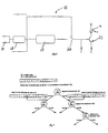
- the processing circuit 10 does not calculate the distance but calculates a new emission value which will be respectively a function of the arithmetic mean of the calculated sum and the minimum or maximum values of the preset range (FIG 7 if there is provided a digital processing block).
- the current circulating in the light source 4 will be changed through the electrical circuits of the processing and drive blocks of FIGS 3, 4, 5 and 6 in such a manner as to generate a light signal of a different magnitude and hence electrical signals in the detection means 7 of a different magnitude from the previous ones.
- control of the current circulating in the light source 4 is performed by controlling the duty cycle of the signal output by the PWM 18.
Landscapes
- Physics & Mathematics (AREA)
- General Physics & Mathematics (AREA)
- Optics & Photonics (AREA)
- Electromagnetism (AREA)
- Engineering & Computer Science (AREA)
- Radar, Positioning & Navigation (AREA)
- Remote Sensing (AREA)
- Measurement Of Optical Distance (AREA)
- Optical Radar Systems And Details Thereof (AREA)
- Length Measuring Devices By Optical Means (AREA)
Priority Applications (5)
| Application Number | Priority Date | Filing Date | Title |
|---|---|---|---|
| EP96830652A EP0851211B1 (en) | 1996-12-24 | 1996-12-24 | Optical distance measuring apparatus and method |
| ES96830652T ES2229258T3 (es) | 1996-12-24 | 1996-12-24 | Procedimiento y aparato optico para medir distancias. |
| DE69633452T DE69633452T2 (de) | 1996-12-24 | 1996-12-24 | Optische Abstandsmessmethode und Vorrichtung |
| US08/996,195 US6122061A (en) | 1996-12-24 | 1997-12-22 | Optical apparatus for measuring the distance of an object and process for measuring the distance of an object from an optical measuring apparatus |
| JP9355349A JPH10227632A (ja) | 1996-12-24 | 1997-12-24 | 対象物の距離測定用光学装置および光学測定装置から対象物への距離測定方法 |
Applications Claiming Priority (1)
| Application Number | Priority Date | Filing Date | Title |
|---|---|---|---|
| EP96830652A EP0851211B1 (en) | 1996-12-24 | 1996-12-24 | Optical distance measuring apparatus and method |
Publications (2)
| Publication Number | Publication Date |
|---|---|
| EP0851211A1 EP0851211A1 (en) | 1998-07-01 |
| EP0851211B1 true EP0851211B1 (en) | 2004-09-22 |
Family
ID=8226095
Family Applications (1)
| Application Number | Title | Priority Date | Filing Date |
|---|---|---|---|
| EP96830652A Expired - Lifetime EP0851211B1 (en) | 1996-12-24 | 1996-12-24 | Optical distance measuring apparatus and method |
Country Status (5)
| Country | Link |
|---|---|
| US (1) | US6122061A (enExample) |
| EP (1) | EP0851211B1 (enExample) |
| JP (1) | JPH10227632A (enExample) |
| DE (1) | DE69633452T2 (enExample) |
| ES (1) | ES2229258T3 (enExample) |
Families Citing this family (7)
| Publication number | Priority date | Publication date | Assignee | Title |
|---|---|---|---|---|
| US6330279B1 (en) * | 1998-02-06 | 2001-12-11 | Seagate Technology Llc | System and method of correcting gain and offset error in a signal amplifier for a position sensitive detector |
| GB9828473D0 (en) | 1998-12-24 | 1999-02-17 | British Aerospace | Non-contact positioning apparatus |
| DE10012522C2 (de) * | 2000-03-15 | 2002-09-26 | Leuze Electronic Gmbh & Co | Distanzsensor |
| ATE456811T1 (de) * | 2003-10-27 | 2010-02-15 | Bea Sa | Entfernungsmessgerät |
| FR2899326B1 (fr) * | 2006-03-31 | 2009-03-06 | H2I Technologies Sa | "procede et dispositif de determination optique de la position d'un objet". |
| JP5670829B2 (ja) * | 2011-05-13 | 2015-02-18 | 株式会社 ソキア・トプコン | 光波距離計 |
| KR102440167B1 (ko) * | 2020-06-03 | 2022-09-06 | 주식회사 나무가 | 거리측정장치 및 거리측정장치의 구동 방법 |
Family Cites Families (9)
| Publication number | Priority date | Publication date | Assignee | Title |
|---|---|---|---|---|
| DE3709614A1 (de) * | 1987-03-24 | 1988-10-20 | Messerschmitt Boelkow Blohm | Verfahren und vorrichtung zur positionsbestimmung |
| US5113080A (en) * | 1990-07-10 | 1992-05-12 | New Jersey Institute Of Technology | Non-linear displacement sensor based on optical triangulation principle |
| JPH05322559A (ja) * | 1992-05-26 | 1993-12-07 | Matsushita Electric Works Ltd | 光学式変位センサ |
| JP3243300B2 (ja) * | 1992-05-26 | 2002-01-07 | 松下電工株式会社 | 変位センサ |
| DE69316354T2 (de) * | 1993-08-03 | 1998-04-30 | Yamatake Honeywell Co Ltd | Verfahren und Gerät zur photoelektrischen Detektion |
| JP3233746B2 (ja) * | 1993-08-24 | 2001-11-26 | 積水化学工業株式会社 | 光位置検出装置 |
| JPH0798223A (ja) * | 1993-09-28 | 1995-04-11 | Canon Inc | 測距装置 |
| JP3513936B2 (ja) * | 1993-12-22 | 2004-03-31 | 松下電工株式会社 | 光走査型変位測定装置 |
| JP3051033B2 (ja) * | 1994-09-28 | 2000-06-12 | 富士写真光機株式会社 | 測距装置 |
-
1996
- 1996-12-24 ES ES96830652T patent/ES2229258T3/es not_active Expired - Lifetime
- 1996-12-24 DE DE69633452T patent/DE69633452T2/de not_active Expired - Lifetime
- 1996-12-24 EP EP96830652A patent/EP0851211B1/en not_active Expired - Lifetime
-
1997
- 1997-12-22 US US08/996,195 patent/US6122061A/en not_active Expired - Fee Related
- 1997-12-24 JP JP9355349A patent/JPH10227632A/ja active Pending
Also Published As
| Publication number | Publication date |
|---|---|
| DE69633452T2 (de) | 2005-09-22 |
| US6122061A (en) | 2000-09-19 |
| JPH10227632A (ja) | 1998-08-25 |
| DE69633452D1 (de) | 2004-10-28 |
| EP0851211A1 (en) | 1998-07-01 |
| ES2229258T3 (es) | 2005-04-16 |
Similar Documents
| Publication | Publication Date | Title |
|---|---|---|
| EP0374614B1 (en) | Method and optical sensor for determining the position of a mobile body | |
| NL8400380A (nl) | Inrichting voor het detecteren van kleurverschillen. | |
| EP0851211B1 (en) | Optical distance measuring apparatus and method | |
| EP0332781B1 (en) | Optical measuring device | |
| US5008695A (en) | Rangefinder for camera | |
| US4533241A (en) | Distance measuring device and automatic focusing system using same | |
| UST102104I4 (en) | Scanning optical system adapted for linewidth measurement in semiconductor devices | |
| JPS5979805A (ja) | 距離センサ | |
| JPS6177701A (ja) | 光学式測定機器におけるエツジ検出装置 | |
| JPS60227112A (ja) | 光変位計 | |
| US4621917A (en) | Automatic focusing adjustment device | |
| JPH0423724B2 (enExample) | ||
| JPH10227632A5 (enExample) | ||
| CN1006935B (zh) | 焊接坡口截面积检测装置 | |
| JPH02171608A (ja) | 距離・角度測定装置 | |
| CN112212789B (zh) | 位置检测系统和位置检测方法 | |
| JP2674468B2 (ja) | 距離検出装置 | |
| JPH0377006A (ja) | 物体形状計測装置 | |
| JPH0674760A (ja) | 光学式変位センサ | |
| JPS59221609A (ja) | 距離測定装置 | |
| JPH02176419A (ja) | 光学式エンコーダ | |
| JPH04134089U (ja) | 光波測距装置 | |
| JPS5928718A (ja) | 遅延回路 | |
| JP2970250B2 (ja) | 測距装置 | |
| JPS58168904A (ja) | 位置変位検出装置 |
Legal Events
| Date | Code | Title | Description |
|---|---|---|---|
| PUAI | Public reference made under article 153(3) epc to a published international application that has entered the european phase |
Free format text: ORIGINAL CODE: 0009012 |
|
| AK | Designated contracting states |
Kind code of ref document: A1 Designated state(s): CH DE DK ES FR GB GR IT LI SE |
|
| AX | Request for extension of the european patent |
Free format text: AL;LT;LV;RO;SI |
|
| 17P | Request for examination filed |
Effective date: 19981126 |
|
| AKX | Designation fees paid |
Free format text: CH DE DK ES FR GB GR IT LI SE |
|
| RBV | Designated contracting states (corrected) |
Designated state(s): CH DE DK ES FR GB GR IT LI SE |
|
| 17Q | First examination report despatched |
Effective date: 20001023 |
|
| RAP1 | Party data changed (applicant data changed or rights of an application transferred) |
Owner name: DATASENSOR S.P.A. |
|
| GRAP | Despatch of communication of intention to grant a patent |
Free format text: ORIGINAL CODE: EPIDOSNIGR1 |
|
| GRAS | Grant fee paid |
Free format text: ORIGINAL CODE: EPIDOSNIGR3 |
|
| GRAA | (expected) grant |
Free format text: ORIGINAL CODE: 0009210 |
|
| RTI1 | Title (correction) |
Free format text: OPTICAL DISTANCE MEASURING APPARATUS AND METHOD |
|
| AK | Designated contracting states |
Kind code of ref document: B1 Designated state(s): CH DE DK ES FR GB GR IT LI SE |
|
| PG25 | Lapsed in a contracting state [announced via postgrant information from national office to epo] |
Ref country code: LI Free format text: LAPSE BECAUSE OF FAILURE TO SUBMIT A TRANSLATION OF THE DESCRIPTION OR TO PAY THE FEE WITHIN THE PRESCRIBED TIME-LIMIT Effective date: 20040922 Ref country code: CH Free format text: LAPSE BECAUSE OF FAILURE TO SUBMIT A TRANSLATION OF THE DESCRIPTION OR TO PAY THE FEE WITHIN THE PRESCRIBED TIME-LIMIT Effective date: 20040922 |
|
| REG | Reference to a national code |
Ref country code: GB Ref legal event code: FG4D |
|
| REG | Reference to a national code |
Ref country code: CH Ref legal event code: EP |
|
| REF | Corresponds to: |
Ref document number: 69633452 Country of ref document: DE Date of ref document: 20041028 Kind code of ref document: P |
|
| PG25 | Lapsed in a contracting state [announced via postgrant information from national office to epo] |
Ref country code: SE Free format text: LAPSE BECAUSE OF FAILURE TO SUBMIT A TRANSLATION OF THE DESCRIPTION OR TO PAY THE FEE WITHIN THE PRESCRIBED TIME-LIMIT Effective date: 20041222 Ref country code: GR Free format text: LAPSE BECAUSE OF FAILURE TO SUBMIT A TRANSLATION OF THE DESCRIPTION OR TO PAY THE FEE WITHIN THE PRESCRIBED TIME-LIMIT Effective date: 20041222 Ref country code: DK Free format text: LAPSE BECAUSE OF FAILURE TO SUBMIT A TRANSLATION OF THE DESCRIPTION OR TO PAY THE FEE WITHIN THE PRESCRIBED TIME-LIMIT Effective date: 20041222 |
|
| REG | Reference to a national code |
Ref country code: CH Ref legal event code: PL |
|
| REG | Reference to a national code |
Ref country code: ES Ref legal event code: FG2A Ref document number: 2229258 Country of ref document: ES Kind code of ref document: T3 |
|
| PLBE | No opposition filed within time limit |
Free format text: ORIGINAL CODE: 0009261 |
|
| STAA | Information on the status of an ep patent application or granted ep patent |
Free format text: STATUS: NO OPPOSITION FILED WITHIN TIME LIMIT |
|
| ET | Fr: translation filed | ||
| 26N | No opposition filed |
Effective date: 20050623 |
|
| PGFP | Annual fee paid to national office [announced via postgrant information from national office to epo] |
Ref country code: GB Payment date: 20101201 Year of fee payment: 15 Ref country code: IT Payment date: 20101129 Year of fee payment: 15 |
|
| PGFP | Annual fee paid to national office [announced via postgrant information from national office to epo] |
Ref country code: DE Payment date: 20101208 Year of fee payment: 15 |
|
| PGFP | Annual fee paid to national office [announced via postgrant information from national office to epo] |
Ref country code: ES Payment date: 20111212 Year of fee payment: 16 |
|
| PGFP | Annual fee paid to national office [announced via postgrant information from national office to epo] |
Ref country code: FR Payment date: 20120119 Year of fee payment: 16 |
|
| GBPC | Gb: european patent ceased through non-payment of renewal fee |
Effective date: 20121224 |
|
| REG | Reference to a national code |
Ref country code: FR Ref legal event code: ST Effective date: 20130830 |
|
| REG | Reference to a national code |
Ref country code: DE Ref legal event code: R119 Ref document number: 69633452 Country of ref document: DE Effective date: 20130702 |
|
| PG25 | Lapsed in a contracting state [announced via postgrant information from national office to epo] |
Ref country code: DE Free format text: LAPSE BECAUSE OF NON-PAYMENT OF DUE FEES Effective date: 20130702 |
|
| PG25 | Lapsed in a contracting state [announced via postgrant information from national office to epo] |
Ref country code: FR Free format text: LAPSE BECAUSE OF NON-PAYMENT OF DUE FEES Effective date: 20130102 Ref country code: GB Free format text: LAPSE BECAUSE OF NON-PAYMENT OF DUE FEES Effective date: 20121224 |
|
| PG25 | Lapsed in a contracting state [announced via postgrant information from national office to epo] |
Ref country code: IT Free format text: LAPSE BECAUSE OF NON-PAYMENT OF DUE FEES Effective date: 20121224 |
|
| REG | Reference to a national code |
Ref country code: ES Ref legal event code: FD2A Effective date: 20140306 |
|
| PG25 | Lapsed in a contracting state [announced via postgrant information from national office to epo] |
Ref country code: ES Free format text: LAPSE BECAUSE OF NON-PAYMENT OF DUE FEES Effective date: 20121225 |