EP0851176A2 - Kesselanlage für einen Wärmeerzeuger - Google Patents
Kesselanlage für einen Wärmeerzeuger Download PDFInfo
- Publication number
- EP0851176A2 EP0851176A2 EP97810921A EP97810921A EP0851176A2 EP 0851176 A2 EP0851176 A2 EP 0851176A2 EP 97810921 A EP97810921 A EP 97810921A EP 97810921 A EP97810921 A EP 97810921A EP 0851176 A2 EP0851176 A2 EP 0851176A2
- Authority
- EP
- European Patent Office
- Prior art keywords
- burner
- premix burner
- boiler system
- flow
- fuel
- Prior art date
- Legal status (The legal status is an assumption and is not a legal conclusion. Google has not performed a legal analysis and makes no representation as to the accuracy of the status listed.)
- Withdrawn
Links
Images


Classifications
-
- F—MECHANICAL ENGINEERING; LIGHTING; HEATING; WEAPONS; BLASTING
- F23—COMBUSTION APPARATUS; COMBUSTION PROCESSES
- F23D—BURNERS
- F23D17/00—Burners for combustion simultaneously or alternately of gaseous or liquid or pulverulent fuel
- F23D17/002—Burners for combustion simultaneously or alternately of gaseous or liquid or pulverulent fuel gaseous or liquid fuel
-
- F—MECHANICAL ENGINEERING; LIGHTING; HEATING; WEAPONS; BLASTING
- F23—COMBUSTION APPARATUS; COMBUSTION PROCESSES
- F23C—METHODS OR APPARATUS FOR COMBUSTION USING FLUID FUEL OR SOLID FUEL SUSPENDED IN A CARRIER GAS OR AIR
- F23C7/00—Combustion apparatus characterised by arrangements for air supply
- F23C7/002—Combustion apparatus characterised by arrangements for air supply the air being submitted to a rotary or spinning motion
-
- F—MECHANICAL ENGINEERING; LIGHTING; HEATING; WEAPONS; BLASTING
- F23—COMBUSTION APPARATUS; COMBUSTION PROCESSES
- F23C—METHODS OR APPARATUS FOR COMBUSTION USING FLUID FUEL OR SOLID FUEL SUSPENDED IN A CARRIER GAS OR AIR
- F23C9/00—Combustion apparatus characterised by arrangements for returning combustion products or flue gases to the combustion chamber
- F23C9/006—Combustion apparatus characterised by arrangements for returning combustion products or flue gases to the combustion chamber the recirculation taking place in the combustion chamber
-
- F—MECHANICAL ENGINEERING; LIGHTING; HEATING; WEAPONS; BLASTING
- F23—COMBUSTION APPARATUS; COMBUSTION PROCESSES
- F23D—BURNERS
- F23D11/00—Burners using a direct spraying action of liquid droplets or vaporised liquid into the combustion space
- F23D11/36—Details
- F23D11/40—Mixing tubes; Burner heads
- F23D11/402—Mixing chambers downstream of the nozzle
-
- F—MECHANICAL ENGINEERING; LIGHTING; HEATING; WEAPONS; BLASTING
- F23—COMBUSTION APPARATUS; COMBUSTION PROCESSES
- F23D—BURNERS
- F23D14/00—Burners for combustion of a gas, e.g. of a gas stored under pressure as a liquid
- F23D14/02—Premix gas burners, i.e. in which gaseous fuel is mixed with combustion air upstream of the combustion zone
-
- F—MECHANICAL ENGINEERING; LIGHTING; HEATING; WEAPONS; BLASTING
- F23—COMBUSTION APPARATUS; COMBUSTION PROCESSES
- F23M—CASINGS, LININGS, WALLS OR DOORS SPECIALLY ADAPTED FOR COMBUSTION CHAMBERS, e.g. FIREBRIDGES; DEVICES FOR DEFLECTING AIR, FLAMES OR COMBUSTION PRODUCTS IN COMBUSTION CHAMBERS; SAFETY ARRANGEMENTS SPECIALLY ADAPTED FOR COMBUSTION APPARATUS; DETAILS OF COMBUSTION CHAMBERS, NOT OTHERWISE PROVIDED FOR
- F23M9/00—Baffles or deflectors for air or combustion products; Flame shields
- F23M9/06—Baffles or deflectors for air or combustion products; Flame shields in fire-boxes
-
- F—MECHANICAL ENGINEERING; LIGHTING; HEATING; WEAPONS; BLASTING
- F23—COMBUSTION APPARATUS; COMBUSTION PROCESSES
- F23C—METHODS OR APPARATUS FOR COMBUSTION USING FLUID FUEL OR SOLID FUEL SUSPENDED IN A CARRIER GAS OR AIR
- F23C2900/00—Special features of, or arrangements for combustion apparatus using fluid fuels or solid fuels suspended in air; Combustion processes therefor
- F23C2900/07002—Premix burners with air inlet slots obtained between offset curved wall surfaces, e.g. double cone burners
-
- F—MECHANICAL ENGINEERING; LIGHTING; HEATING; WEAPONS; BLASTING
- F23—COMBUSTION APPARATUS; COMBUSTION PROCESSES
- F23D—BURNERS
- F23D2209/00—Safety arrangements
- F23D2209/20—Flame lift-off / stability
Definitions
- the present invention relates to a boiler system according to Preamble of claim 1.
- the invention seeks to remedy this.
- the invention how it is characterized in the claims, the task lies the basis for a boiler system of the type mentioned Take measures to prevent excessive cooling the reacted backflow gases prevented.
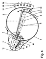
- FIG. 1 shows a boiler system 100, as is usually the case for Heating furnaces is used.
- This boiler system 100 exists essentially from a flame tube 101 Combustion chamber 17 by a heat-resistant partition 106 is surrounded.
- the boiler system is powered by a premix burner operated, the description of Fig. 3 and 4 emerges in more detail.
- a rod-shaped holder 104 on the outflow side which is a limitation on the expansion of this Backflow zone 24 acts in the direction of flow.
- This out Disc 103 and bracket 104 has existing limit a low heat capacity, and preferably consists of a heat-resistant material.
- Fig. 2 shows a further embodiment of the device for Limitation of the expansion side of the return flow zone.
- the disk 103 is held by individual supports 105, which are supported on the flame tube 101.
- the others Considerations under Fig. 1 are also valid here.
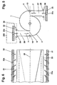
- Fig. 3 shows a premix burner in perspective. It is for a better understanding of the subject advantageous if at the same time in the acquisition of FIG. 3 at least Fig. 4 is used. These two figures have mainly the purpose, the type and the functioning of such a burner.
- Partial bodies 1, 2 which are nested offset from one another are and with a gaseous and / or liquid fuel is operated.
- Cone-shaped is not only shown here by one understood the defined cone shape, it also closes other configurations of the partial bodies with a, such a diffuser or diffuser-like shape as well a confuser or confuser-like shape. These forms are not specifically shown here because they are the expert are well known.
- the transfer of the respective Central axis or longitudinal axis of symmetry of the partial bodies 1, 2 to each other see Fig. 4, Pos.
- each one tangential Air inlet duct 5, 6 free through which the combustion air 7 inside the premix burner, i.e. in the cone cavity 8 flows.
- the two conical partial bodies 1, 2 each have a cylindrical starting part 9, 10, the likewise, analogously to the aforementioned partial bodies 1, 2 run to each other so that the tangential Air inlet channels 5, 6 over the entire length of the premix burner available.
- a nozzle 11 for preferably atomizing a liquid fuel 12 housed such that their injection approximately with the narrowest cross section of the the partial body 1, 2 formed conical cavity 8 coincides.
- the injection capacity and the operating mode of this Nozzle 11 depends on the given parameters of the respective Premix burner.
- Fuel 12 can, if necessary, with a recirculated exhaust gas be enriched; then it is also possible through the Nozzle 11 the complementary injection of an amount of water accomplish.
- the premix burner can be purely conical, thus be designed without cylindrical starting parts 9, 10.
- the sub-bodies 1, 2 also each have a fuel line 13, 14 on which along the tangential inlet channels 5, 6 arranged and with injection openings 15 are provided, by which preferably a gaseous Fuel 16 into the combustion air 7 flowing there is injected, as symbolized by arrows 16 is, this injection at the same time the fuel injection level (See Fig. 4, item 22) of the system.
- This Fuel lines 13, 14 are preferably at the latest End of tangential inflow, before entering the cone cavity 8, placed this around an optimal air / fuel mixture to ensure.
- the premix burner On the combustion chamber side, the premix burner has an anchor for the partial body 1, 2 serving front panel 18 with a Number of holes 19 through which, if necessary Mixed or cooling air 20 the front part of the combustion chamber 17th or whose wall is fed.
- the premix burner becomes alone operated by means of a liquid fuel 12, so happens this through the central nozzle 11, this fuel 12 then into the cone cavity at an acute angle 8 or is injected into the combustion chamber 17.
- a conical fuel profile 23 is formed, which is formed by the tangentially flowing rotating combustion air 7 is enclosed. In the axial direction, the concentration of the injected fuel 12 continuously through the inflowing Combustion air 7 degraded to an optimal mixture.
- the optimal fuel concentration across the cross-section is only in the area of vertebral bursting, i.e. in the area the backflow zone 24 reached. Only at this point then a stable flame front 25.
- the flame stabilizing Effect results from that in the cone cavity 8 forming swirl number in the direction of flow along the cone axis. A backlash of the flame inside the premix burner is prevented.
- the flow opening is minimized of the tangential air inlet ducts 6, 7 is predestined is the backflow zone 24 from the end of the premixing section to build.
- the design of the premix burner is suitable furthermore excellent, the flow opening of the tangential To change air inlet channels 5, 6 as required, with what without changing the overall length of the premix burner relatively large operational bandwidth can be captured.
- the partial bodies 1, 2 are also in another Plane can be shifted towards each other, creating even Overlap in relation to the air inlet plane in the cone cavity 8 (See FIG. 4, item 21) of the same in the area of tangential air inlet ducts 5, 6, as shown in FIG. 4 emerges, can be accomplished. Then it is also possible, the partial body 1, 2 by rotating in opposite directions Interlacing movement in a spiral.
- Premix burners of the type described here are also those which is used to achieve a swirl flow from a cylindrical or quasi-cylindrical tube, the inflow the combustion air into the interior of the pipe also tangential air inlet ducts are created, and inside the tube a conical body with in Flow direction decreasing cross section is arranged, with what even with this configuration a critical swirl number on Output of the burner can be achieved.
- FIG. 4 shows the same premix burner according to FIG. 3, however from a different perspective and in a simplified representation.
- This Figure 4 is essentially intended to serve the The configuration of this premix burner can be recorded perfectly.
- the central axis 3, 4 run parallel here to each other.
- Fig. 5 is a section approximately in the middle of the premix burner.
- the feed channels arranged tangentially in mirror image 27, 28 perform the function of a mixing section, in which the combustion air 7, formed from fresh air 29 and recirculated flue gas 30 is perfected.
- the combustion air 7 is processed in an injector system 200. Upstream of each feed channel 27, 28, the tangential Inflow into the interior 8 of the premix burner, the fresh air 29 along the entire length of this premix burner evenly distributed over perforated plates 31, 32. In Flow direction to the tangential inlet channels 5, 6 are perforated plates 31, 32.
- the local injector configuration 200 is characterized by this from that the geometry of the premix burner, in particular what the shape and size of the tangential air intake ducts 5, 6 concerns, remains dimensionally stable, i.e. through the evenly dosed distribution of the hot gases 30 along the entire axial length of the premix burner does not arise thermal distortions.
- the same injector configuration like the one just described here, can also be in the area the head-side fuel nozzle 11 for an axial supply a combustion air can be provided.
- FIG. 6 is a schematic representation of the premix burner in the direction of flow, in particular the course of the Injector system belonging perforated plates 31, 32 compared to the Inflow planes 33 of the feed channels 27, 28 are expressed is coming.
- This course is parallel, with the inflow planes 33 even parallel over the entire length of the burner run to the burner axis 26 of the premix burner.
- the injector nozzles 31a, 32a their inflow angle with respect to the burner axis 26 of the Change the premix burner in the direction of flow. From one initial acute angle in the head section of the premix burner Gradually sit up until you are in the area of the output approximately perpendicular to the burner axis 26 stand. With this precaution, the mixture quality of the Combustion air increased and the return flow zone stable held.
- variable inflow angle corresponds to the injector nozzles 34a, 35a in the flow direction here too largely the configuration according to FIGS. 5 and 6, whereby here the gradual erection of these injector nozzles 34a, 35a for a vertical inflow in the area the output of the premix burner primarily compared to the Inflow plane 36 of the respective feed channel is aimed.
Landscapes
- Engineering & Computer Science (AREA)
- Chemical & Material Sciences (AREA)
- Combustion & Propulsion (AREA)
- Mechanical Engineering (AREA)
- General Engineering & Computer Science (AREA)
Abstract
Description
- Fig. 1
- eine Kesselanlage, welche mit einem Vormischbrenner betrieben wird, mit einer Vorrichtung für die Limitierung der Ausdehnung der Rückströmzone,
- Fig. 2
- eine weitere Ausgestaltung der Vorrichtung für die Limitierung der Ausdehnung der Rückströmzone,
- Fig. 3
- einen Vormischbrenner zum Betrieb der Kesselanlage, in perspektivischer Darstellung,
- Fig. 4
- eine weitere perspektivische Darstellung dieses Vormischbrenners aus anderer Ansicht in vereinfachter Form,
- Fig. 5
- einen Schnitt durch den Vormischbrenner gemäss Fig. 2 oder 3, mit Injektoren bestückt, wobei die Einströmungsebene von Zuführungskanälen parallel zur Brennerachse verlaufen,
- Fig. 6
- eine Konfiguration des Injektorsystems in Strömungsrichtung,
- Fig. 7
- eine weitere Ausgestaltung der Einströmungsebene von Zuführungskanälen und
- Fig. 8
- eine weitere Konfiguration des Injektorsystems in Strömungsrichtung.
- 1, 2
- Kegelförmige Teilkörper
- 3, 4
- Mittelachse zu 1 resp. 2
- 5, 6
- Tangentiale Lufteintrittskanäle
- 7
- Verbrennungsluft
- 8
- Kegelhohlraum, Innenraum des Brenners
- 9, 10
- Zylindrische Anfangsteile des Brenners
- 11
- Brennstoffdüse
- 12
- Brennstoff, Flüssiger Brennstoff
- 13, 14
- Brennstoffleitungen
- 15
- Eindüsungsöffnungen der Brennstoffleitung 13, 14
- 16
- Brennstoff, gasförmiger Brennstoff
- 17
- Brennraum
- 18
- Frontplatte
- 19
- Bohrungen in Frontplatte
- 20
- Luft, Mischluft, Kühlluft
- 21
- Lufteintrittsebene
- 22
- Brennstoffinjektionsebene
- 23
- Brennstoffprofil
- 24
- Rückströmzone, Rückströmblase
- 25
- Flammenfront
- 26
- Hauptmittelachse, Brennerachse
- 27, 28
- Zuführungskanäle
- 29
- Frischluft
- 30
- Rückgeführtes Rauchgas
- 31, 32
- Lochplatten
- 31a, 32a
- Injektordüsen
- 33
- Einströmungsebene der Züführungskanäle 27, 28
- 34, 35
- Lochplatten
- 34a, 35a
- Injektordüsen
- 36
- Einströmungsebene der Zuführungskanäle 27, 28
- 100
- Kesselanlage
- 101
- Flammrohr
- 102
- Abgaszone
- 103
- Scheibe
- 104
- Stabförmige Halterung
- 105
- Stützen
- 106
- Schottung
- 200
- Injektorsystem
Claims (11)
- Kesselanlage für eine Wärmeerzeugung, im wesentlichen bestehend aus einem Brennraum und einem kopfseitig der Kesselanlage wirkenden Vormischbrenner für den Betrieb mit einem flüssigen und/oder gasförmigen Brennstoff, wobei eine Verbrennungsluft durch tangentiale Lufteintrittskanäle in eine durch die axiale Erstreckung des Vormischbrenners gebildete Vormischstrecke einströmt, und wobei der Vormischbrenner eine Ausgestaltung aufweist oder Mittel beinhaltet, welche eine kritische Drallzahl an dessen Ausgang induzieren, dadurch gekennzeichnet, dass im Brennraum (17) der Kesselanlage (100), abströmungsseitig des Ausganges (18) des Vormischbrenners, eine Begrenzungvorrichtung (103, 104, 105) gegen eine Ausbreitung einer vom Vormischbrenner gebildeten Rückströmzone (24) angeordnet ist.
- Kesselanlage nach Anspruch 1, dadurch gekennzeichnet, dass die Begrenzungsvorrichtung aus einer durch mindestens einer Abstützung (104, 105) mittig gehaltenen Scheibe (103) besteht.
- Kesselanlage nach Anspruch 1, dadurch gekennzeichnet, dass der Vormischbrenner aus mindestens zwei hohlen, kegelförmigen, in Strömungsrichtung ineinandergeschachtelten Teilkörper (1, 2) besteht, dass die Mittelachsen (3, 4) dieser Teilkörper (1, 2) zueinander versetzt verlaufen, dergestalt, dass benachbarte Wandungen der Teilkörper (1, 2) tangentiale Lufteintrittskanäle (5, 6) für eine Verbrennungsluft (7) bilden, und dass der Vormischbrenner mit mindestens einer Brennstoffdüse (11, 15) betreibbar ist.
- Kesselanlage nach Anspruch 3, dadurch gekennzeichnet, dass die Brennstoffdüse (11) kopfseitig und auf der Brennerachse (26) angeordnet ist.
- Kesselanlage nach Anspruch 3, dadurch gekennzeichnet, dass im Bereich der tangentialen Lufteintrittskanäle (5, 6) in Längserstreckung des Vormischbrenners eine Anzahl zueinander beabstandeter Brennstoffdüsen (15) angeordnet sind.
- Kesselanlage nach Anspruch 3, dadurch gekennzeichnet, dass der Durchflussquerschnitt eines von den Teilkörpern (1, 2) gebildeten Kegelhohlraumes (8) in Strömungsrichtung gleichförmig zunimmt.
- Kesselanlage nach Anspruch 3, dadurch gekennzeichnet, dass der Durchflussquerschnitt eines von den Teilkörpern (1, 2) gebildeten Kegelhohlraumes (8) einen Diffusor, einen diffusorähnlichen Verlauf, einen Konfusor, einen konfusorähnlichen Verlauf bildet.
- Kesselanlage nach Anspruch 3, dadurch gekennzeichnet, dass die Teilkörper (1, 2) spiralförmig ineinander geschachtelt sind.
- Kesselanlage nach Anspruch 3, dadurch gekennzeichnet, dass sich in radialer oder quasi-radialer Richtung gegenüber den Lufteintrittskanäle (5, 6) Zuführungskanäle (27, 27) erstrecken, welche je mindestens ein Injektorsysten (200) für die Bereitstellung einer aus Frischluft (29) und Rauchgas (30) bestehenden Verbrennungsluft (7) aufweisen.
- Kesselanlage nach Anspruch 9, dadurch gekennzeichnet, dass zum Injektorsystem gehörige Lochplatten (31, 32; 34, 35) parallel zur jeweiligen Einströmungsebene (33, 36) der Verbrennungsluft (7) in die Zuführungskanäle (27, 28) verlaufen, dass die Lochplatten im Bereich der Einströmungsebenen mit Injektordüsen (31a, 32a; 34a, 35a) versehen sind, und dass der Einströmungswinkel der Injektordüsen in Axialrichtung des Vormischbrenners gegenüber der Brennerachse (26) fortlaufend veränderbar ist.
- Kesselanlage nach Anspruch 10, dadurch gekennzeichnet, dass die Durchflussebene der Injektordüsen (31a, 32a; 34a, 35a) im Bereich der Kopfstufe des Vormischbrenners einen spitzen Winkel aufweist, und dass dieser Winkel in axialer Richtung der Lochplatten (31, 32; 34, 35) allmählich zunimmt bis dieser im Bereich des Ausganges des Vormischbrenners weitgehend senkrecht zur Einströmungsebenen (33, 36) der Zuführungskanäle (25, 26) und/oder zur Brennerachse (26) des Vormischbrenners steht.
Applications Claiming Priority (2)
| Application Number | Priority Date | Filing Date | Title |
|---|---|---|---|
| DE19654741 | 1996-12-30 | ||
| DE1996154741 DE19654741A1 (de) | 1996-12-30 | 1996-12-30 | Kesselanlage für eine Wärmeerzeugung |
Publications (2)
| Publication Number | Publication Date |
|---|---|
| EP0851176A2 true EP0851176A2 (de) | 1998-07-01 |
| EP0851176A3 EP0851176A3 (de) | 1999-01-20 |
Family
ID=7816417
Family Applications (1)
| Application Number | Title | Priority Date | Filing Date |
|---|---|---|---|
| EP97810921A Withdrawn EP0851176A3 (de) | 1996-12-30 | 1997-11-27 | Kesselanlage für einen Wärmeerzeuger |
Country Status (2)
| Country | Link |
|---|---|
| EP (1) | EP0851176A3 (de) |
| DE (1) | DE19654741A1 (de) |
Cited By (1)
| Publication number | Priority date | Publication date | Assignee | Title |
|---|---|---|---|---|
| EP0985876A1 (de) * | 1998-09-10 | 2000-03-15 | Abb Research Ltd. | Brenner |
Citations (1)
| Publication number | Priority date | Publication date | Assignee | Title |
|---|---|---|---|---|
| EP0321809B1 (de) | 1987-12-21 | 1991-05-15 | BBC Brown Boveri AG | Verfahren für die Verbrennung von flüssigem Brennstoff in einem Brenner |
Family Cites Families (9)
| Publication number | Priority date | Publication date | Assignee | Title |
|---|---|---|---|---|
| DE2250766A1 (de) * | 1972-10-17 | 1974-04-18 | Volkswagenwerk Ag | Brenner, insbesondere fuer fahrzeuge |
| DE3011249A1 (de) * | 1980-03-24 | 1982-01-21 | Thermostar Heisler + Leins oHG Heizungs-und Klimatechnik, 7250 Leonberg | Flammrohr eines oelvergasungsbrenners |
| DE3341305A1 (de) * | 1983-11-15 | 1985-05-30 | Walter 7000 Stuttgart Swoboda | Vergasungsoelbrenner |
| GB2155609B (en) * | 1984-03-09 | 1986-10-22 | Walter William Pritchard | Heat exchanger; space heater, |
| CH680157A5 (de) * | 1989-12-01 | 1992-06-30 | Asea Brown Boveri | |
| DE4320212A1 (de) * | 1993-06-18 | 1994-12-22 | Abb Research Ltd | Feuerungsanlage |
| DE4426353A1 (de) * | 1994-07-25 | 1996-02-01 | Abb Research Ltd | Brenner |
| DE4446541A1 (de) * | 1994-12-24 | 1996-06-27 | Abb Management Ag | Brennkammer |
| DE19545036A1 (de) * | 1995-12-02 | 1997-06-05 | Abb Research Ltd | Vormischbrenner |
-
1996
- 1996-12-30 DE DE1996154741 patent/DE19654741A1/de not_active Withdrawn
-
1997
- 1997-11-27 EP EP97810921A patent/EP0851176A3/de not_active Withdrawn
Patent Citations (1)
| Publication number | Priority date | Publication date | Assignee | Title |
|---|---|---|---|---|
| EP0321809B1 (de) | 1987-12-21 | 1991-05-15 | BBC Brown Boveri AG | Verfahren für die Verbrennung von flüssigem Brennstoff in einem Brenner |
Cited By (1)
| Publication number | Priority date | Publication date | Assignee | Title |
|---|---|---|---|---|
| EP0985876A1 (de) * | 1998-09-10 | 2000-03-15 | Abb Research Ltd. | Brenner |
Also Published As
| Publication number | Publication date |
|---|---|
| DE19654741A1 (de) | 1998-07-02 |
| EP0851176A3 (de) | 1999-01-20 |
Similar Documents
| Publication | Publication Date | Title |
|---|---|---|
| EP0387532B1 (de) | Brennkammer einer Gasturbine | |
| EP0401529B1 (de) | Brennkammer einer Gasturbine | |
| EP0745809A1 (de) | Wirbelgenerator für Brennkammer | |
| EP0481111B1 (de) | Brennkammer einer Gasturbine | |
| EP0777081B1 (de) | Vormischbrenner | |
| EP0694740A2 (de) | Brennkammer | |
| CH674561A5 (de) | ||
| EP0724114A2 (de) | Brenner | |
| DE19654009B4 (de) | Vormischbrenner zum Betrieb einer Brennkammer mit einem flüssigen und/oder gasförmigen Brennstoff | |
| EP0851172B1 (de) | Brenner und Verfahren zum Betrieb einer Brennkammer mit einem flüssigen und/oder gasförmigen Brennstoff | |
| EP0629817A2 (de) | Feuerungsanlage | |
| EP0641971A2 (de) | Verfahren zum Betrieb eines Vormischbrenners | |
| EP0394911B1 (de) | Feuerungsanlage | |
| EP0394800B1 (de) | Vormischbrenner für die Heissgaserzeugung | |
| EP0483554B1 (de) | Verfahren zur Minimierung der NOx-Emissionen aus einer Verbrennung | |
| EP0740108A2 (de) | Brenner | |
| DE19507088B4 (de) | Vormischbrenner | |
| DE4412315A1 (de) | Verfahren und Vorrichtung zum Betreiben der Brennkammer einer Gasturbine | |
| EP0777082A2 (de) | Vormischbrenner | |
| DE4242003A1 (de) | Prozesswärmeerzeuger | |
| EP0866268B1 (de) | Verfahren zum Betrieb eines drallstabilisierten Brenners sowie Brenner zur Durchführung des Verfahrens | |
| EP0866269B1 (de) | Kesselanlage für eine Wärmeerzeugung | |
| EP0780628B1 (de) | Vormischbrenner für einen Wärmeerzeuger | |
| EP0851176A2 (de) | Kesselanlage für einen Wärmeerzeuger | |
| EP0866267B1 (de) | Verfahren zum Betrieb einer Kesselanlage und die Kesselanlage |
Legal Events
| Date | Code | Title | Description |
|---|---|---|---|
| PUAI | Public reference made under article 153(3) epc to a published international application that has entered the european phase |
Free format text: ORIGINAL CODE: 0009012 |
|
| AK | Designated contracting states |
Kind code of ref document: A2 Designated state(s): AT BE CH DE DK ES FI FR GB GR IE IT LI LU MC NL PT SE |
|
| AX | Request for extension of the european patent |
Free format text: AL;LT;LV;MK;RO;SI |
|
| PUAL | Search report despatched |
Free format text: ORIGINAL CODE: 0009013 |
|
| AK | Designated contracting states |
Kind code of ref document: A3 Designated state(s): AT BE CH DE DK ES FI FR GB GR IE IT LI LU MC NL PT SE |
|
| AX | Request for extension of the european patent |
Free format text: AL;LT;LV;MK;RO;SI |
|
| AKX | Designation fees paid | ||
| STAA | Information on the status of an ep patent application or granted ep patent |
Free format text: STATUS: THE APPLICATION IS DEEMED TO BE WITHDRAWN |
|
| 18D | Application deemed to be withdrawn |
Effective date: 19990721 |
|
| REG | Reference to a national code |
Ref country code: DE Ref legal event code: 8566 |