EP0866267B1 - Verfahren zum Betrieb einer Kesselanlage und die Kesselanlage - Google Patents
Verfahren zum Betrieb einer Kesselanlage und die Kesselanlage Download PDFInfo
- Publication number
- EP0866267B1 EP0866267B1 EP97810163A EP97810163A EP0866267B1 EP 0866267 B1 EP0866267 B1 EP 0866267B1 EP 97810163 A EP97810163 A EP 97810163A EP 97810163 A EP97810163 A EP 97810163A EP 0866267 B1 EP0866267 B1 EP 0866267B1
- Authority
- EP
- European Patent Office
- Prior art keywords
- burner
- air
- boiler plant
- combustion
- air plenum
- Prior art date
- Legal status (The legal status is an assumption and is not a legal conclusion. Google has not performed a legal analysis and makes no representation as to the accuracy of the status listed.)
- Expired - Lifetime
Links
Images


Classifications
-
- F—MECHANICAL ENGINEERING; LIGHTING; HEATING; WEAPONS; BLASTING
- F23—COMBUSTION APPARATUS; COMBUSTION PROCESSES
- F23D—BURNERS
- F23D17/00—Burners for combustion simultaneously or alternately of gaseous or liquid or pulverulent fuel
- F23D17/002—Burners for combustion simultaneously or alternately of gaseous or liquid or pulverulent fuel gaseous or liquid fuel
-
- F—MECHANICAL ENGINEERING; LIGHTING; HEATING; WEAPONS; BLASTING
- F23—COMBUSTION APPARATUS; COMBUSTION PROCESSES
- F23C—METHODS OR APPARATUS FOR COMBUSTION USING FLUID FUEL OR SOLID FUEL SUSPENDED IN A CARRIER GAS OR AIR
- F23C7/00—Combustion apparatus characterised by arrangements for air supply
- F23C7/002—Combustion apparatus characterised by arrangements for air supply the air being submitted to a rotary or spinning motion
-
- F—MECHANICAL ENGINEERING; LIGHTING; HEATING; WEAPONS; BLASTING
- F23—COMBUSTION APPARATUS; COMBUSTION PROCESSES
- F23C—METHODS OR APPARATUS FOR COMBUSTION USING FLUID FUEL OR SOLID FUEL SUSPENDED IN A CARRIER GAS OR AIR
- F23C9/00—Combustion apparatus characterised by arrangements for returning combustion products or flue gases to the combustion chamber
- F23C9/006—Combustion apparatus characterised by arrangements for returning combustion products or flue gases to the combustion chamber the recirculation taking place in the combustion chamber
-
- F—MECHANICAL ENGINEERING; LIGHTING; HEATING; WEAPONS; BLASTING
- F23—COMBUSTION APPARATUS; COMBUSTION PROCESSES
- F23D—BURNERS
- F23D11/00—Burners using a direct spraying action of liquid droplets or vaporised liquid into the combustion space
- F23D11/36—Details
- F23D11/42—Starting devices
-
- F—MECHANICAL ENGINEERING; LIGHTING; HEATING; WEAPONS; BLASTING
- F23—COMBUSTION APPARATUS; COMBUSTION PROCESSES
- F23C—METHODS OR APPARATUS FOR COMBUSTION USING FLUID FUEL OR SOLID FUEL SUSPENDED IN A CARRIER GAS OR AIR
- F23C2900/00—Special features of, or arrangements for combustion apparatus using fluid fuels or solid fuels suspended in air; Combustion processes therefor
- F23C2900/07002—Premix burners with air inlet slots obtained between offset curved wall surfaces, e.g. double cone burners
Definitions
- the invention relates to a method according to the preamble of claim 1 also a boiler plant to carry out this process.
- EP-A-0 617 231 shows a method for operating a burner for boilers with exhaust gas recirculation for the purpose of reducing pollutants be operated from the combustion chamber of the heating core into the burner.
- the invention seeks to remedy this.
- the invention as set out in the claims is characterized, the task is based on a method of the beginning to propose the type of steps mentioned, which are the operation of such a boiler system influence favorably in all aspects.
- the main advantage of the invention is the fact that with a Near stoichiometric fuel / air mixture in the burner favorable ignition conditions created and the pollutant emissions at the start extremely reduced become.
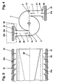
- FIG. 1 shows a boiler system 100, as is usually the case for heating furnaces is used.
- This boiler system essentially consists of one Flame tube 101 formed combustion chamber 102 by a heat resistant Partition 103 is surrounded.
- the boiler system is here by a premix burner operated, the description of which is apparent from FIGS. 2 and 3.
- Combustion chamber 102 has an air plenum on the head side 104, which supplies the premix burner with air. Feeding this Air plenum 104 is preferably not based on an upstream one fan shown, which delivers air under a defined admission pressure.
- the starting air 105 which also originates from the air plenum 104, is determined for and suitable locations are injected into the premix burner, also during the introduction this start air 105 support flame stabilization, increase the quality of the ignition behavior and the minimization of pollutant emissions stand in the foreground during the start-up phase.
- the blower consists of a solenoid valve 106 which has an opening 107 to the outside releases. Control of this solenoid valve 106 when the admission pressure is reduced in the plenum 104 during the start-up phase can be easily realized, whereby of course also other directly controlled blow-off devices here possible are. The reduction can be made in terms of time and amount in each case Adjust conditions. Autonomous start air management via a separate one Solenoid valve can also be realized.
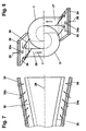
- FIG. 2 shows a premix burner in perspective.
- FIG. 3 shows a premix burner in perspective.
- the premix burner according to FIG. 2 consists of two hollow, conical partial bodies 1, 2, which are nested offset from one another and with a gaseous and / or liquid fuel is operated.
- a gaseous and / or liquid fuel is operated.
- the one shown here becomes “conical” due to a fixed opening angle characterized cone shape understood, but it also includes other configurations the partial body with a, such a diffuser or diffuser-like shape as well a confuser or confuser-like shape. These forms are not present Specifically shown, since they are familiar to those skilled in the art.
- the dislocation the respective central axis or longitudinal axis of symmetry of the partial bodies 1, 2 to each other see Fig. 3, Pos.
- each tangential air inlet duct 5, 6 free through which the Combustion air 7 in the interior of the premix burner, i.e. in the cone cavity 8 streams.
- the two conical partial bodies 1, 2 each have a cylindrical one Initial part 9, 10, which also, analogous to the aforementioned partial bodies 1, 2, offset run to each other so that the tangential air inlet channels 5, 6 over the entire length of the premix burner is available.
- a nozzle 11 for preferably atomizing a liquid Fuel 12 housed, such that their injection approximately with the narrowest cross-section of the cone cavity formed by the partial bodies 1, 2 8 coincides.
- This nozzle 11 depends on the specified parameters of the respective premix burner.
- the fuel 12 injected through the nozzle 11 can, if necessary, with a recycled exhaust gas are enriched; then it is also possible through the Nozzle 11 to accomplish the complementary injection of a quantity of water.
- the premix burner can be purely conical, i.e. without a cylindrical one Initial parts 9, 10 may be formed.
- the sub-bodies 1, 2 also each have one Fuel line 13, 14, which runs along the tangential inlet channels 5, 6 are arranged and provided with injection openings 15, through which preferably a gaseous fuel 16 in the combustion air flowing there 7 is injected, as is symbolized by arrows 16, wherein this injection also the fuel injection level (see FIG. 3, item 22) of the Systems forms.
- These fuel lines 13, 14 are preferably at the latest placed at the end of the tangential inflow, before entering the cone cavity 8, this to ensure an optimal air / fuel mixture.
- the premix burner On the combustion chamber side, the premix burner has an anchorage for the partial bodies 1, 2 serving front panel 18 with a number of holes 19 through which if necessary, a mixed or cooling air 20 the front part of the combustion chamber 17th or whose wall is fed.
- the premix burner is used solely by means of a liquid Operated fuel 12, this is done via the central nozzle 11, wherein this fuel 12 then enters the cone cavity 8 at an acute angle or is injected into the combustion chamber 17.
- the nozzle 11 thus forms a tapered fuel profile 23 rotating from the tangentially flowing Combustion air 7 is enclosed. In the axial direction, the concentration of the injected fuel 12 continuously through the incoming combustion air 7 broken down into an optimal mixture.
- a backflow zone 24 (vortex breakdown) also forms there with one opposite the flame front 25 acting there stabilizing effect, in which Meaning that the backflow zone 24 functions as a disembodied flame holder takes over.
- the optimal fuel concentration across the cross section is only in the area the vortex runout, that is, in the area of the backflow zone 24.
- a stable flame front 25 is then created at this point Effect results from the swirl number in formed in the cone cavity 8 Flow direction along the cone axis. A backlash of the flame into that This prevents the interior of the premix burner.
- the flow opening of the tangential is minimized Air inlet channels 6, 7 is predestined, the backflow zone 24 from the end of Form premixing section.
- the design of the premix burner is suitable furthermore excellent, the flow opening of the tangential air inlet ducts 5, 6 to change as required, which means without changing the overall length of the premix burner a relatively large operational bandwidth can be covered.
- the partial bodies 1, 2 are also in a different plane to one another displaceable, which even overlaps the air inlet plane into the cone cavity 8 (see FIG. 3, item 21) of the same in the area of the tangential air inlet channels 5, 6, as shown in Fig. 4, accomplished can be. It is then also possible for the partial bodies 1, 2 to be counter-rotating to interleave rotating movement in a spiral.
- the premix burner is not open the number shown is limited. A larger number is displayed there, for example, when it comes to making the premixing wider, or the Swirl number and thus the dependent formation of the backflow zone 24 by to influence a larger number of air inlet ducts accordingly.
- Premix burners of the type described here are also those which are to be achieved a swirl flow from a cylindrical or quasi-cylindrical tube go out, the inflow of combustion air into the interior of the pipe Tangential air inlet channels is also accomplished, and inside of the tube a conical body with decreasing in the flow direction Cross section is arranged, which is also critical with this configuration Swirl number at the output of the burner can be achieved.
- FIG. 3 shows the same premix burner according to FIG. 2, but from a different one Perspective and in a simplified representation.
- This Figure 3 is essentially serve to correctly record the configuration of this premix burner.
- This dislocation in itself induces the size of the Flow openings of the tangential air inlet ducts 5, 6.
- the central axis 3, 4 run parallel to each other here.
- Fig. 4 is a section approximately in the middle of the premix burner.
- the mirror image Tangentially arranged feed channels 27, 28 perform the function of Mixing section in which the combustion air 7, formed from fresh air 29 and recirculated flue gas 30 is perfected.
- the combustion air 7 is in one Injector system 200 processed. Upstream of each feed channel 27, 28, the serves as a tangential inflow into the interior 8 of the premix burner the fresh air 29 evenly over the entire length of the premix burner Perforated plates 31, 32 distributed. In the direction of flow to the tangential inlet channels 5, 6 these perforated plates 31, 32 are perforated.
- the perforations fulfill the function individual injector nozzles 31a, 32a, which have a suction effect compared to the surrounding flue gas 30 exert such that each of these injector nozzle 31a, 32a each only sucks a certain proportion of flue gas 30, whereupon over the entire axial length of the perforated plates 31, 32, which corresponds to the burner length, a uniform flue gas admixture takes place.
- This configuration causes that at the point of contact of the two media, i.e. the fresh air 29 and the flue gas 30, an intimate mixing takes place, so that the up to the tangential air inlet slots 5, 6 reaching flow length of the supply channels 27, 28 can be minimized for the mixture formation.
- the local injector configuration 200 is distinguished by the fact that the geometry the premix burner, especially what the shape and size of the tangential Air inlet ducts 5, 6 concerns, remains dimensionally stable, i.e. through the evenly dosed distribution of the hot flue gases 30 along the entire axial Length of the premix burner, there are no heat-related distortions.
- the same injector configuration as the one just described here can also be used in the area of the head-side fuel nozzle 11 for an axial supply of a Combustion air can be provided.
- FIG. 5 is a schematic representation of the premix burner in the flow direction, where in particular the course of the perforated plates belonging to the injector system 31, 32 with respect to the inflow planes 33 of the feed channels 27, 28 is expressed. This course is parallel, with the inflow levels 33 itself over the entire burner length parallel to the burner axis 26 of the Premix burner.
- This figure also shows how the injector nozzles 31a, 32a their inflow angle with respect to the burner axis 26 of the Change the premix burner in the direction of flow. From an initial spike They gradually align angles in the head section of the premix burner until it is approximately perpendicular to the burner axis in the area of the outlet 26 stand. With this precaution the mixture quality of the combustion air increased and the backflow zone held stable.
- the angle of inflow the injector nozzles mentioned with respect to the burner axis can, however be designed vertically in certain operating modes.
- FIGS. 6 and 7 show essentially the same configuration according to FIGS. 4 and 5, wherein the perforated plates 34, 35 with the associated injector nozzles 34a, 35a also parallel over the entire burner length to the inflow planes 36 of the feed channels 27, 28 run. Meanwhile, these inflow planes 36 run conically with respect to the burner axis 26 of the premix burner.
- the variable inflow angle of the injector nozzles 34a, 35a in the flow direction also largely corresponds to the configuration according to FIGS. 4 and 5, wherein here the gradual erection of these injector nozzles 34a, 35a into one vertical inflow in the area of the outlet of the premix burner primary with respect to the inflow plane 36 of the respective feed channel directed.
Landscapes
- Engineering & Computer Science (AREA)
- Chemical & Material Sciences (AREA)
- Combustion & Propulsion (AREA)
- Mechanical Engineering (AREA)
- General Engineering & Computer Science (AREA)
- Control Of Steam Boilers And Waste-Gas Boilers (AREA)
- Combustion Of Fluid Fuel (AREA)
Description
- Fig. 1
- eine Kesselanlage, welche mit einem Vormischbrenner betrieben wird, mit einer Vorrichtung zur Regulierung der Startluft für einen Brenner mit Rauchgasrückführung,
- Fig. 2
- einen Vormischbrenner zum Betrieb der Kesselanlage, in perspektivischer Darstellung,
- Fig. 3
- eine weitere perspektivische Darstellung dieses Vormischbrenners aus anderer Ansicht in vereinfachter Form,
- Fig. 4
- einen Schnitt durch den Vormischbrenner gemäss Fig.2 oder 3, mit Injektoren bestückt, wobei die Einströmungsebene von Zuführungskanälen parallel zur Brennerachse verlaufen,
- Fig. 5
- eine Konfiguration des Injektorsystems in Strömungsrichtung,
- Fig. 6
- eine weitere Ausgestaltung der Einströmungsebene von Zuführungskanälen und
- Fig. 7
- eine weitere Konfiguration des Injektorsystems in Strömungsrichtung.
- 1, 2
- Kegelförmige Teilkörper
- 3, 4
- Mittelachse zu 1 resp. 2
- 5, 6
- Tangentiale Lufteintrittskanäle
- 7
- Verbrennungsluft
- 8
- Kegelhohlraum, Innenraum des Brenners
- 9, 10
- Zylindrische Anfangsteile des Brenners
- 11
- Brennstoffdüse
- 12
- Brennstoff, Flüssiger Brennstoff
- 13, 14
- Brennstoffleitungen
- 15
- Eindüsungsöffnungen der Brennstoffleitung 13, 14
- 16
- Brennstoff, gasförmiger Brennstoff
- 17
- Vorderer Teil des Brennraumes durch die Blende 103 eingegrenzt
- 18
- Frontplatte
- 19
- Bohrungen in Frontplatte
- 20
- Luft, Mischluft, Kühlluft
- 21
- Lufteintrittsebene
- 22
- Brennstoffinjektionsebene
- 23
- Brennstoffprofil
- 24
- Innere Rückströmzone, Rückströmblase
- 24a
- Rückströmzone, Rückströmblase ohne Einbauten im Brennraum
- 25
- Flammenfront
- 26
- Hauptmittelachse, Brennerachse
- 27, 28
- Zuführungskanäle
- 29
- Frischluft
- 30
- Rückgeführtes Rauchgas, reagierte Gase, äussere Rückströmzone
- 31, 32
- Lochplatten
- 31a, 32a
- Injektordüsen
- 33
- Einströmungsebene der Züführungskanäle 27, 28
- 34, 35
- Lochplatten
- 34a, 35a
- Injektordüsen
- 36
- Einströmungsebene der Zuführungskanäle 27, 28
- 100
- Kesselanlage
- 101
- Flammrohr
- 102
- Brennraum
- 103
- Schottung
- 104
- Luftplenum
- 105
- Startluft
- 106
- Abblasevorrichtung, Magnetventil
- 107
- Oeffnung nach aussen
- 200
- Injektorsystem
Claims (10)
- Verfahren zum Betrieb einer Kesselanlage (100) für eine Wärmeerzeugung, welche Kesselanlage (100) im wesentlichen aus einem gespeisten Luftplenum (104) und einem mit dem Luftplenum (104) in Wirkverbindung stehenden Brennraum (102) besteht, wobei kopfseitig des Brennraumes (102) ein mit einem flüssigen und/oder gasförmigen Brennstoff betreibbaren Brenner angeordnet ist, und wobei dieser Brenner Mittel aufweist, welche mindestens im Zusammenhang mit der Einbringung einer Verbrennungsluft (7) aus dem Luftplenum (104) eine Flammenstabilisierung im Brennraum (102) bewirken, dadurch gekennzeichnet, dass während der Startphase mindestens eine mit dem Luftplenum (104) in Wirkverbindung stehende Abblasevorrichtung (106) aktiviert wird, über welche der Vordruck in dem Luftplenum (104) zeitlich und betragsmässig abgesenkt wird.
- Kesselanlage zur Durchführung des Verfahrens nach Anspruch 1, wobei die Kesselanlage (100) im wesentlichen aus einem gespeisten Luftplenum (104) und einem mit dem Luftplenum (104) in Wirkverbindung stehenden Brennraum (102) besteht, wobei kopfseitig des Brennraumes (102) ein mit einem flüssigen und/oder gasförmigen Brennstoff betreibbaren Brenner angeordnet ist, der aus mindestens zwei hohlen, kegelförmigen, in Strömungsrichtung ineinandergeschachtelten Teilkörpern (1, 2) besteht, wobei die Mittelachsen (3, 4) dieser Teilkörper (1, 2) zueinander versetzt verlaufen, dergestalt, dass benachbarte Wandungen der Teilkörper (1, 2) tangentiale Lufteintrittskanäle (5, 6) für eine Verbrennungsluft (7) bilden, und wobei der Brenner mit mindestens einer Brennstoffdüse (11, 15) betreibbar ist,
wobei dieser Brenner Mittel aufweist, weiche mindestens im Zusammenhang mit der Einbringung einer Verbrennungsluft (7) aus dem Luftplenum (104) eine Flammenstabilisierung im Brennraum (102) bewirken,
und wobei die Kesselanlage (100) eine mit dem Luftplenum (104) in Wirkverbindung stehende Abblasevorrichung (106) aufweist. - Kesselanlage nach Anspruch 2, dadurch gekennzeichnet, dass die Brennstoffdüse (11) kopfseitig und auf der Brennerachse (26) angeordnet ist.
- Kesselanlage nach Anspruch 2, dadurch gekennzeichnet, dass im Bereich der tangentialen Lufteintrittskanäle (5, 6) in Längserstreckung des Brenners eine Anzahl zueinander beabstandeter Brennstoffdüsen (15) angeordnet sind.
- Kesselanlage nach Anspruch 2, dadurch gekennzeichnet, dass der Durchflussquerschnitt eines von den Teilkörpern (1, 2) gebildeten Kegelhohlraumes (8) in Strömungsrichtung gleichförmig zunimmt.
- Kesselanlage nach Anspruch 2, dadurch gekennzeichnet, dass der Durchflussquerschnitt eines von den Teilkörpem (1, 2) gebildeten Kegelhohlraumes (8) einen Diffusor, einen diffusorähnlichen Verlauf, einen Konfusor, einen konfusorähnlichen Verlauf bildet.
- Kesselanlage nach Anspruch 2, dadurch gekennzeichnet, dass die Teilkörper (1, 2) spiralförmig ineinander geschachtelt sind.
- Kesselanlage nach Anspruch 2, dadurch gekennzeichnet, dass sich in radialer oder quasi-radialer Richtung gegenüber den Lufteintrittskanäle (5, 6) Zuführungskanäle (27, 27) erstrecken, welche je mindestens ein Injektorsysten (200) für die Bereitstellung einer aus Frischluft (29) und reagierten Gasen (30) bestehenden Verbrennungsluft (7) aufweisen.
- Kesselanlage nach Anspruch 8, dadurch gekennzeichnet, dass zum Injektorsystem gehörige Lochplatten (31, 32; 34, 35) parallel zur jeweiligen Einströmungsebene (33, 36) der Verbrennungsluft (7) in die Zuführungskanäle(27, 28) verlaufen, dass die Lochplatten im Bereich der Einströmungsebenen mit Injektordüsen (31a, 32a; 34a, 35a) versehen sind, und dass der Einströmungswinkel der Injektordüsen in Axialrichtung des Brenners gegenüber der Brennerachse (26) rechtwinklig oder fortlaufend veränderbar ist.
- Kesselanlage nach Anspruch 9, dadurch gekennzeichnet, dass die Durchflussebene der Injektordüsen (31a, 32a; 34a, 35a) im Bereich der Kopfstufe des Brenners einen spitzen Winkel aufweist, und dass dieser Winkel in axialer Richtung der Lochplatten (31, 32; 34, 35) allmählich zunimmt bis dieser im Bereich des Ausganges des Brenners weitgehend senkrecht zur Einströmungsebenen (33, 36) der Zuführungskanäle (25, 26) und/oder zur Brennerachse (26) steht.
Priority Applications (7)
| Application Number | Priority Date | Filing Date | Title |
|---|---|---|---|
| DE59709311T DE59709311D1 (de) | 1997-03-18 | 1997-03-18 | Verfahren zum Betrieb einer Kesselanlage und die Kesselanlage |
| PT97810163T PT866267E (pt) | 1997-03-18 | 1997-03-18 | Processo de exploracao de uma instalacao de caldeira e a instalacao de caldeira |
| DK97810163T DK0866267T3 (da) | 1997-03-18 | 1997-03-18 | Fremgangsmåde til drift af et kedelanlæg og kedelanlæg |
| ES97810163T ES2192664T3 (es) | 1997-03-18 | 1997-03-18 | Procedimiento para el funcionamiento de una instalacion de caldera e instalacion de caldera. |
| AT97810163T ATE232588T1 (de) | 1997-03-18 | 1997-03-18 | Verfahren zum betrieb einer kesselanlage und die kesselanlage |
| EP97810163A EP0866267B1 (de) | 1997-03-18 | 1997-03-18 | Verfahren zum Betrieb einer Kesselanlage und die Kesselanlage |
| US09/032,842 US6009840A (en) | 1997-03-18 | 1998-03-02 | Method for operating a boiler plant |
Applications Claiming Priority (1)
| Application Number | Priority Date | Filing Date | Title |
|---|---|---|---|
| EP97810163A EP0866267B1 (de) | 1997-03-18 | 1997-03-18 | Verfahren zum Betrieb einer Kesselanlage und die Kesselanlage |
Publications (2)
| Publication Number | Publication Date |
|---|---|
| EP0866267A1 EP0866267A1 (de) | 1998-09-23 |
| EP0866267B1 true EP0866267B1 (de) | 2003-02-12 |
Family
ID=8230180
Family Applications (1)
| Application Number | Title | Priority Date | Filing Date |
|---|---|---|---|
| EP97810163A Expired - Lifetime EP0866267B1 (de) | 1997-03-18 | 1997-03-18 | Verfahren zum Betrieb einer Kesselanlage und die Kesselanlage |
Country Status (7)
| Country | Link |
|---|---|
| US (1) | US6009840A (de) |
| EP (1) | EP0866267B1 (de) |
| AT (1) | ATE232588T1 (de) |
| DE (1) | DE59709311D1 (de) |
| DK (1) | DK0866267T3 (de) |
| ES (1) | ES2192664T3 (de) |
| PT (1) | PT866267E (de) |
Families Citing this family (2)
| Publication number | Priority date | Publication date | Assignee | Title |
|---|---|---|---|---|
| EP1262714A1 (de) | 2001-06-01 | 2002-12-04 | ALSTOM (Switzerland) Ltd | Brenner mit Abgasrückführung |
| CN112413571B (zh) * | 2020-11-19 | 2023-07-18 | 西安西热锅炉环保工程有限公司 | 一种天然气锅炉综合利用系统及其运行方法 |
Family Cites Families (9)
| Publication number | Priority date | Publication date | Assignee | Title |
|---|---|---|---|---|
| US2623482A (en) * | 1951-01-25 | 1952-12-30 | William P Ayers | Pressure-relief door for heating units |
| US2835230A (en) * | 1954-01-11 | 1958-05-20 | Cleaver Brooks Co | Boiler |
| DE3740047C2 (de) * | 1987-11-26 | 1994-07-21 | Man Technologie Gmbh | Verfahren und Vorrichtung zur Steuerung der Verbrennungsluft für einen Brenner |
| US4940042A (en) * | 1988-08-24 | 1990-07-10 | Mor-Flo Industries, Inc. | System and apparatus for venting water heater |
| GB2227822B (en) * | 1989-02-04 | 1993-05-26 | Copermill Ltd | Improvements in or relating to safety apparatus |
| CH680157A5 (de) * | 1989-12-01 | 1992-06-30 | Asea Brown Boveri | |
| US5636619A (en) * | 1993-02-18 | 1997-06-10 | The University Of Chicago | Method and apparatus for reducing cold-phase emissions by utilizing oxygen-enriched intake air |
| DE4309115A1 (de) * | 1993-03-23 | 1994-09-29 | Viessmann Werke Kg | Verfahren zum Betrieb eines Ölverdampfungsbrenners |
| DE4320212A1 (de) * | 1993-06-18 | 1994-12-22 | Abb Research Ltd | Feuerungsanlage |
-
1997
- 1997-03-18 PT PT97810163T patent/PT866267E/pt unknown
- 1997-03-18 EP EP97810163A patent/EP0866267B1/de not_active Expired - Lifetime
- 1997-03-18 DK DK97810163T patent/DK0866267T3/da active
- 1997-03-18 AT AT97810163T patent/ATE232588T1/de not_active IP Right Cessation
- 1997-03-18 DE DE59709311T patent/DE59709311D1/de not_active Expired - Lifetime
- 1997-03-18 ES ES97810163T patent/ES2192664T3/es not_active Expired - Lifetime
-
1998
- 1998-03-02 US US09/032,842 patent/US6009840A/en not_active Expired - Lifetime
Also Published As
| Publication number | Publication date |
|---|---|
| ES2192664T3 (es) | 2003-10-16 |
| US6009840A (en) | 2000-01-04 |
| PT866267E (pt) | 2003-06-30 |
| DE59709311D1 (de) | 2003-03-20 |
| ATE232588T1 (de) | 2003-02-15 |
| DK0866267T3 (da) | 2003-05-26 |
| EP0866267A1 (de) | 1998-09-23 |
Similar Documents
| Publication | Publication Date | Title |
|---|---|---|
| EP0321809B1 (de) | Verfahren für die Verbrennung von flüssigem Brennstoff in einem Brenner | |
| EP0503319B1 (de) | Brenner für eine Vormischverbrennung eines flüssigen und/oder gasförmigen Brennstoffes | |
| EP0777081B1 (de) | Vormischbrenner | |
| EP0694740A2 (de) | Brennkammer | |
| EP0387532A1 (de) | Brennkammer einer Gasturbine | |
| EP0401529A1 (de) | Brennkammer einer Gasturbine | |
| EP0481111B1 (de) | Brennkammer einer Gasturbine | |
| EP0392158B1 (de) | Verfahren zum Betrieb einer Feuerungsanlage mit fossilen Brennstoffen | |
| EP0629817A2 (de) | Feuerungsanlage | |
| EP0394800B1 (de) | Vormischbrenner für die Heissgaserzeugung | |
| EP0394911B1 (de) | Feuerungsanlage | |
| EP0641971A2 (de) | Verfahren zum Betrieb eines Vormischbrenners | |
| EP0816759B1 (de) | Vormischbrenner und Verfahren zum Betrieb des Brenners | |
| EP0483554B1 (de) | Verfahren zur Minimierung der NOx-Emissionen aus einer Verbrennung | |
| EP0740108A2 (de) | Brenner | |
| EP0866268B1 (de) | Verfahren zum Betrieb eines drallstabilisierten Brenners sowie Brenner zur Durchführung des Verfahrens | |
| EP0777082A2 (de) | Vormischbrenner | |
| EP0690263B1 (de) | Verfahren zum Betrieb einer Feuerungsanlage | |
| EP0430011B1 (de) | Brenner zur Verbrennung von flüssigen oder gasförmigen Brennstoffen | |
| DE4242003A1 (de) | Prozesswärmeerzeuger | |
| EP0866267B1 (de) | Verfahren zum Betrieb einer Kesselanlage und die Kesselanlage | |
| EP0866269B1 (de) | Kesselanlage für eine Wärmeerzeugung | |
| DE19721937B4 (de) | Vormischbrenner zum Betrieb eines Aggregates zur Erzeugung eines Heissgases | |
| DE19505614A1 (de) | Verfahren zum Betrieb eines Vormischbrenners | |
| EP0881431A2 (de) | Brenner zum Betrieb eines Aggregates zur Erzeugung eines Heissgases |
Legal Events
| Date | Code | Title | Description |
|---|---|---|---|
| PUAI | Public reference made under article 153(3) epc to a published international application that has entered the european phase |
Free format text: ORIGINAL CODE: 0009012 |
|
| AK | Designated contracting states |
Kind code of ref document: A1 Designated state(s): AT BE CH DE DK ES FI FR GB IT LI NL PT SE |
|
| AX | Request for extension of the european patent |
Free format text: AL;LT;LV;RO;SI |
|
| 17P | Request for examination filed |
Effective date: 19990302 |
|
| AKX | Designation fees paid |
Free format text: AT CH DE DK ES FI FR IT LI NL PT SE |
|
| RBV | Designated contracting states (corrected) |
Designated state(s): AT CH DE DK ES FI FR IT LI NL PT SE |
|
| RBV | Designated contracting states (corrected) |
Designated state(s): AT BE CH DE DK ES FI FR GB IT LI NL PT SE |
|
| RAP1 | Party data changed (applicant data changed or rights of an application transferred) |
Owner name: ALSTOM |
|
| RTI1 | Title (correction) |
Free format text: METHOD OF OPERATING A BOILER AND THE BOILER |
|
| GRAH | Despatch of communication of intention to grant a patent |
Free format text: ORIGINAL CODE: EPIDOS IGRA |
|
| RTI1 | Title (correction) |
Free format text: METHOD OF OPERATING A BOILER AND THE BOILER |
|
| GRAH | Despatch of communication of intention to grant a patent |
Free format text: ORIGINAL CODE: EPIDOS IGRA |
|
| RAP1 | Party data changed (applicant data changed or rights of an application transferred) |
Owner name: ALSTOM (SWITZERLAND) LTD |
|
| GRAA | (expected) grant |
Free format text: ORIGINAL CODE: 0009210 |
|
| AK | Designated contracting states |
Designated state(s): AT BE CH DE DK ES FI FR GB IT LI NL PT SE |
|
| REG | Reference to a national code |
Ref country code: GB Ref legal event code: FG4D Free format text: NOT ENGLISH |
|
| REG | Reference to a national code |
Ref country code: CH Ref legal event code: EP |
|
| REF | Corresponds to: |
Ref document number: 59709311 Country of ref document: DE Date of ref document: 20030320 Kind code of ref document: P |
|
| REG | Reference to a national code |
Ref country code: SE Ref legal event code: TRGR |
|
| REG | Reference to a national code |
Ref country code: DK Ref legal event code: T3 |
|
| GBT | Gb: translation of ep patent filed (gb section 77(6)(a)/1977) |
Effective date: 20030506 |
|
| REG | Reference to a national code |
Ref country code: PT Ref legal event code: SC4A Free format text: AVAILABILITY OF NATIONAL TRANSLATION Effective date: 20030512 |
|
| ET | Fr: translation filed | ||
| REG | Reference to a national code |
Ref country code: ES Ref legal event code: FG2A Ref document number: 2192664 Country of ref document: ES Kind code of ref document: T3 |
|
| PLBE | No opposition filed within time limit |
Free format text: ORIGINAL CODE: 0009261 |
|
| STAA | Information on the status of an ep patent application or granted ep patent |
Free format text: STATUS: NO OPPOSITION FILED WITHIN TIME LIMIT |
|
| 26N | No opposition filed |
Effective date: 20031113 |
|
| PGFP | Annual fee paid to national office [announced via postgrant information from national office to epo] |
Ref country code: SE Payment date: 20091223 Year of fee payment: 14 |
|
| PGFP | Annual fee paid to national office [announced via postgrant information from national office to epo] |
Ref country code: PT Payment date: 20100106 Year of fee payment: 14 Ref country code: ES Payment date: 20100323 Year of fee payment: 14 Ref country code: DK Payment date: 20100208 Year of fee payment: 14 Ref country code: CH Payment date: 20100218 Year of fee payment: 14 |
|
| PGFP | Annual fee paid to national office [announced via postgrant information from national office to epo] |
Ref country code: IT Payment date: 20100320 Year of fee payment: 14 Ref country code: FR Payment date: 20100318 Year of fee payment: 14 Ref country code: FI Payment date: 20100301 Year of fee payment: 14 |
|
| PGFP | Annual fee paid to national office [announced via postgrant information from national office to epo] |
Ref country code: GB Payment date: 20100208 Year of fee payment: 14 Ref country code: AT Payment date: 20100208 Year of fee payment: 14 |
|
| PGFP | Annual fee paid to national office [announced via postgrant information from national office to epo] |
Ref country code: NL Payment date: 20100308 Year of fee payment: 14 Ref country code: DE Payment date: 20100331 Year of fee payment: 14 |
|
| PGFP | Annual fee paid to national office [announced via postgrant information from national office to epo] |
Ref country code: BE Payment date: 20100504 Year of fee payment: 14 |
|
| REG | Reference to a national code |
Ref country code: PT Ref legal event code: MM4A Free format text: LAPSE DUE TO NON-PAYMENT OF FEES Effective date: 20110919 |
|
| BERE | Be: lapsed |
Owner name: *ALSTOM (SWITZERLAND) LTD Effective date: 20110331 |
|
| REG | Reference to a national code |
Ref country code: NL Ref legal event code: V1 Effective date: 20111001 |
|
| PG25 | Lapsed in a contracting state [announced via postgrant information from national office to epo] |
Ref country code: PT Free format text: LAPSE BECAUSE OF NON-PAYMENT OF DUE FEES Effective date: 20110919 |
|
| REG | Reference to a national code |
Ref country code: CH Ref legal event code: PL Ref country code: DK Ref legal event code: EBP |
|
| REG | Reference to a national code |
Ref country code: SE Ref legal event code: EUG |
|
| GBPC | Gb: european patent ceased through non-payment of renewal fee |
Effective date: 20110318 |
|
| PG25 | Lapsed in a contracting state [announced via postgrant information from national office to epo] |
Ref country code: FI Free format text: LAPSE BECAUSE OF NON-PAYMENT OF DUE FEES Effective date: 20110318 Ref country code: AT Free format text: LAPSE BECAUSE OF NON-PAYMENT OF DUE FEES Effective date: 20110318 |
|
| REG | Reference to a national code |
Ref country code: FR Ref legal event code: ST Effective date: 20111130 |
|
| PG25 | Lapsed in a contracting state [announced via postgrant information from national office to epo] |
Ref country code: BE Free format text: LAPSE BECAUSE OF NON-PAYMENT OF DUE FEES Effective date: 20110331 |
|
| PG25 | Lapsed in a contracting state [announced via postgrant information from national office to epo] |
Ref country code: CH Free format text: LAPSE BECAUSE OF NON-PAYMENT OF DUE FEES Effective date: 20110331 Ref country code: LI Free format text: LAPSE BECAUSE OF NON-PAYMENT OF DUE FEES Effective date: 20110331 Ref country code: DE Free format text: LAPSE BECAUSE OF NON-PAYMENT OF DUE FEES Effective date: 20111001 Ref country code: NL Free format text: LAPSE BECAUSE OF NON-PAYMENT OF DUE FEES Effective date: 20111001 Ref country code: FR Free format text: LAPSE BECAUSE OF NON-PAYMENT OF DUE FEES Effective date: 20110331 |
|
| REG | Reference to a national code |
Ref country code: DE Ref legal event code: R119 Ref document number: 59709311 Country of ref document: DE Effective date: 20111001 |
|
| PG25 | Lapsed in a contracting state [announced via postgrant information from national office to epo] |
Ref country code: IT Free format text: LAPSE BECAUSE OF NON-PAYMENT OF DUE FEES Effective date: 20110318 Ref country code: GB Free format text: LAPSE BECAUSE OF NON-PAYMENT OF DUE FEES Effective date: 20110318 |
|
| REG | Reference to a national code |
Ref country code: ES Ref legal event code: FD2A Effective date: 20120424 |
|
| PG25 | Lapsed in a contracting state [announced via postgrant information from national office to epo] |
Ref country code: DK Free format text: LAPSE BECAUSE OF NON-PAYMENT OF DUE FEES Effective date: 20110331 |
|
| PG25 | Lapsed in a contracting state [announced via postgrant information from national office to epo] |
Ref country code: ES Free format text: LAPSE BECAUSE OF NON-PAYMENT OF DUE FEES Effective date: 20110319 |
|
| PG25 | Lapsed in a contracting state [announced via postgrant information from national office to epo] |
Ref country code: SE Free format text: LAPSE BECAUSE OF NON-PAYMENT OF DUE FEES Effective date: 20110319 |