EP0851176A2 - Boiler for a heat generator - Google Patents
Boiler for a heat generator Download PDFInfo
- Publication number
- EP0851176A2 EP0851176A2 EP97810921A EP97810921A EP0851176A2 EP 0851176 A2 EP0851176 A2 EP 0851176A2 EP 97810921 A EP97810921 A EP 97810921A EP 97810921 A EP97810921 A EP 97810921A EP 0851176 A2 EP0851176 A2 EP 0851176A2
- Authority
- EP
- European Patent Office
- Prior art keywords
- burner
- premix burner
- boiler system
- flow
- fuel
- Prior art date
- Legal status (The legal status is an assumption and is not a legal conclusion. Google has not performed a legal analysis and makes no representation as to the accuracy of the status listed.)
- Withdrawn
Links
Images


Classifications
-
- F—MECHANICAL ENGINEERING; LIGHTING; HEATING; WEAPONS; BLASTING
- F23—COMBUSTION APPARATUS; COMBUSTION PROCESSES
- F23D—BURNERS
- F23D17/00—Burners for combustion conjointly or alternatively of gaseous or liquid or pulverulent fuel
- F23D17/002—Burners for combustion conjointly or alternatively of gaseous or liquid or pulverulent fuel gaseous or liquid fuel
-
- F—MECHANICAL ENGINEERING; LIGHTING; HEATING; WEAPONS; BLASTING
- F23—COMBUSTION APPARATUS; COMBUSTION PROCESSES
- F23C—METHODS OR APPARATUS FOR COMBUSTION USING FLUID FUEL OR SOLID FUEL SUSPENDED IN A CARRIER GAS OR AIR
- F23C7/00—Combustion apparatus characterised by arrangements for air supply
- F23C7/002—Combustion apparatus characterised by arrangements for air supply the air being submitted to a rotary or spinning motion
-
- F—MECHANICAL ENGINEERING; LIGHTING; HEATING; WEAPONS; BLASTING
- F23—COMBUSTION APPARATUS; COMBUSTION PROCESSES
- F23C—METHODS OR APPARATUS FOR COMBUSTION USING FLUID FUEL OR SOLID FUEL SUSPENDED IN A CARRIER GAS OR AIR
- F23C9/00—Combustion apparatus characterised by arrangements for returning combustion products or flue gases to the combustion chamber
- F23C9/006—Combustion apparatus characterised by arrangements for returning combustion products or flue gases to the combustion chamber the recirculation taking place in the combustion chamber
-
- F—MECHANICAL ENGINEERING; LIGHTING; HEATING; WEAPONS; BLASTING
- F23—COMBUSTION APPARATUS; COMBUSTION PROCESSES
- F23D—BURNERS
- F23D11/00—Burners using a direct spraying action of liquid droplets or vaporised liquid into the combustion space
- F23D11/36—Details, e.g. burner cooling means, noise reduction means
- F23D11/40—Mixing tubes or chambers; Burner heads
- F23D11/402—Mixing chambers downstream of the nozzle
-
- F—MECHANICAL ENGINEERING; LIGHTING; HEATING; WEAPONS; BLASTING
- F23—COMBUSTION APPARATUS; COMBUSTION PROCESSES
- F23D—BURNERS
- F23D14/00—Burners for combustion of a gas, e.g. of a gas stored under pressure as a liquid
- F23D14/02—Premix gas burners, i.e. in which gaseous fuel is mixed with combustion air upstream of the combustion zone
-
- F—MECHANICAL ENGINEERING; LIGHTING; HEATING; WEAPONS; BLASTING
- F23—COMBUSTION APPARATUS; COMBUSTION PROCESSES
- F23M—CASINGS, LININGS, WALLS OR DOORS SPECIALLY ADAPTED FOR COMBUSTION CHAMBERS, e.g. FIREBRIDGES; DEVICES FOR DEFLECTING AIR, FLAMES OR COMBUSTION PRODUCTS IN COMBUSTION CHAMBERS; SAFETY ARRANGEMENTS SPECIALLY ADAPTED FOR COMBUSTION APPARATUS; DETAILS OF COMBUSTION CHAMBERS, NOT OTHERWISE PROVIDED FOR
- F23M9/00—Baffles or deflectors for air or combustion products; Flame shields
- F23M9/06—Baffles or deflectors for air or combustion products; Flame shields in fire-boxes
-
- F—MECHANICAL ENGINEERING; LIGHTING; HEATING; WEAPONS; BLASTING
- F23—COMBUSTION APPARATUS; COMBUSTION PROCESSES
- F23C—METHODS OR APPARATUS FOR COMBUSTION USING FLUID FUEL OR SOLID FUEL SUSPENDED IN A CARRIER GAS OR AIR
- F23C2900/00—Special features of, or arrangements for combustion apparatus using fluid fuels or solid fuels suspended in air; Combustion processes therefor
- F23C2900/07002—Premix burners with air inlet slots obtained between offset curved wall surfaces, e.g. double cone burners
-
- F—MECHANICAL ENGINEERING; LIGHTING; HEATING; WEAPONS; BLASTING
- F23—COMBUSTION APPARATUS; COMBUSTION PROCESSES
- F23D—BURNERS
- F23D2209/00—Safety arrangements
- F23D2209/20—Flame lift-off / stability
Definitions
- the present invention relates to a boiler system according to Preamble of claim 1.
- the invention seeks to remedy this.
- the invention how it is characterized in the claims, the task lies the basis for a boiler system of the type mentioned Take measures to prevent excessive cooling the reacted backflow gases prevented.
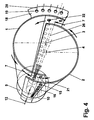
- FIG. 1 shows a boiler system 100, as is usually the case for Heating furnaces is used.
- This boiler system 100 exists essentially from a flame tube 101 Combustion chamber 17 by a heat-resistant partition 106 is surrounded.
- the boiler system is powered by a premix burner operated, the description of Fig. 3 and 4 emerges in more detail.
- a rod-shaped holder 104 on the outflow side which is a limitation on the expansion of this Backflow zone 24 acts in the direction of flow.
- This out Disc 103 and bracket 104 has existing limit a low heat capacity, and preferably consists of a heat-resistant material.
- Fig. 2 shows a further embodiment of the device for Limitation of the expansion side of the return flow zone.
- the disk 103 is held by individual supports 105, which are supported on the flame tube 101.
- the others Considerations under Fig. 1 are also valid here.
- Fig. 3 shows a premix burner in perspective. It is for a better understanding of the subject advantageous if at the same time in the acquisition of FIG. 3 at least Fig. 4 is used. These two figures have mainly the purpose, the type and the functioning of such a burner.
- Partial bodies 1, 2 which are nested offset from one another are and with a gaseous and / or liquid fuel is operated.
- Cone-shaped is not only shown here by one understood the defined cone shape, it also closes other configurations of the partial bodies with a, such a diffuser or diffuser-like shape as well a confuser or confuser-like shape. These forms are not specifically shown here because they are the expert are well known.
- the transfer of the respective Central axis or longitudinal axis of symmetry of the partial bodies 1, 2 to each other see Fig. 4, Pos.
- each one tangential Air inlet duct 5, 6 free through which the combustion air 7 inside the premix burner, i.e. in the cone cavity 8 flows.
- the two conical partial bodies 1, 2 each have a cylindrical starting part 9, 10, the likewise, analogously to the aforementioned partial bodies 1, 2 run to each other so that the tangential Air inlet channels 5, 6 over the entire length of the premix burner available.
- a nozzle 11 for preferably atomizing a liquid fuel 12 housed such that their injection approximately with the narrowest cross section of the the partial body 1, 2 formed conical cavity 8 coincides.
- the injection capacity and the operating mode of this Nozzle 11 depends on the given parameters of the respective Premix burner.
- Fuel 12 can, if necessary, with a recirculated exhaust gas be enriched; then it is also possible through the Nozzle 11 the complementary injection of an amount of water accomplish.
- the premix burner can be purely conical, thus be designed without cylindrical starting parts 9, 10.
- the sub-bodies 1, 2 also each have a fuel line 13, 14 on which along the tangential inlet channels 5, 6 arranged and with injection openings 15 are provided, by which preferably a gaseous Fuel 16 into the combustion air 7 flowing there is injected, as symbolized by arrows 16 is, this injection at the same time the fuel injection level (See Fig. 4, item 22) of the system.
- This Fuel lines 13, 14 are preferably at the latest End of tangential inflow, before entering the cone cavity 8, placed this around an optimal air / fuel mixture to ensure.
- the premix burner On the combustion chamber side, the premix burner has an anchor for the partial body 1, 2 serving front panel 18 with a Number of holes 19 through which, if necessary Mixed or cooling air 20 the front part of the combustion chamber 17th or whose wall is fed.
- the premix burner becomes alone operated by means of a liquid fuel 12, so happens this through the central nozzle 11, this fuel 12 then into the cone cavity at an acute angle 8 or is injected into the combustion chamber 17.
- a conical fuel profile 23 is formed, which is formed by the tangentially flowing rotating combustion air 7 is enclosed. In the axial direction, the concentration of the injected fuel 12 continuously through the inflowing Combustion air 7 degraded to an optimal mixture.
- the optimal fuel concentration across the cross-section is only in the area of vertebral bursting, i.e. in the area the backflow zone 24 reached. Only at this point then a stable flame front 25.
- the flame stabilizing Effect results from that in the cone cavity 8 forming swirl number in the direction of flow along the cone axis. A backlash of the flame inside the premix burner is prevented.
- the flow opening is minimized of the tangential air inlet ducts 6, 7 is predestined is the backflow zone 24 from the end of the premixing section to build.
- the design of the premix burner is suitable furthermore excellent, the flow opening of the tangential To change air inlet channels 5, 6 as required, with what without changing the overall length of the premix burner relatively large operational bandwidth can be captured.
- the partial bodies 1, 2 are also in another Plane can be shifted towards each other, creating even Overlap in relation to the air inlet plane in the cone cavity 8 (See FIG. 4, item 21) of the same in the area of tangential air inlet ducts 5, 6, as shown in FIG. 4 emerges, can be accomplished. Then it is also possible, the partial body 1, 2 by rotating in opposite directions Interlacing movement in a spiral.
- Premix burners of the type described here are also those which is used to achieve a swirl flow from a cylindrical or quasi-cylindrical tube, the inflow the combustion air into the interior of the pipe also tangential air inlet ducts are created, and inside the tube a conical body with in Flow direction decreasing cross section is arranged, with what even with this configuration a critical swirl number on Output of the burner can be achieved.
- FIG. 4 shows the same premix burner according to FIG. 3, however from a different perspective and in a simplified representation.
- This Figure 4 is essentially intended to serve the The configuration of this premix burner can be recorded perfectly.
- the central axis 3, 4 run parallel here to each other.
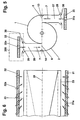
- Fig. 5 is a section approximately in the middle of the premix burner.
- the feed channels arranged tangentially in mirror image 27, 28 perform the function of a mixing section, in which the combustion air 7, formed from fresh air 29 and recirculated flue gas 30 is perfected.
- the combustion air 7 is processed in an injector system 200. Upstream of each feed channel 27, 28, the tangential Inflow into the interior 8 of the premix burner, the fresh air 29 along the entire length of this premix burner evenly distributed over perforated plates 31, 32. In Flow direction to the tangential inlet channels 5, 6 are perforated plates 31, 32.
- the local injector configuration 200 is characterized by this from that the geometry of the premix burner, in particular what the shape and size of the tangential air intake ducts 5, 6 concerns, remains dimensionally stable, i.e. through the evenly dosed distribution of the hot gases 30 along the entire axial length of the premix burner does not arise thermal distortions.
- the same injector configuration like the one just described here, can also be in the area the head-side fuel nozzle 11 for an axial supply a combustion air can be provided.
- FIG. 6 is a schematic representation of the premix burner in the direction of flow, in particular the course of the Injector system belonging perforated plates 31, 32 compared to the Inflow planes 33 of the feed channels 27, 28 are expressed is coming.
- This course is parallel, with the inflow planes 33 even parallel over the entire length of the burner run to the burner axis 26 of the premix burner.
- the injector nozzles 31a, 32a their inflow angle with respect to the burner axis 26 of the Change the premix burner in the direction of flow. From one initial acute angle in the head section of the premix burner Gradually sit up until you are in the area of the output approximately perpendicular to the burner axis 26 stand. With this precaution, the mixture quality of the Combustion air increased and the return flow zone stable held.
- variable inflow angle corresponds to the injector nozzles 34a, 35a in the flow direction here too largely the configuration according to FIGS. 5 and 6, whereby here the gradual erection of these injector nozzles 34a, 35a for a vertical inflow in the area the output of the premix burner primarily compared to the Inflow plane 36 of the respective feed channel is aimed.
Abstract
Description
Die vorliegende Erfindung betrifft eine Kesselanlage gemäss Oberbegriff des Anspruchs 1.The present invention relates to a boiler system according to Preamble of claim 1.
Die Flammenstabilisierung von vielen modernen Low-NOx-Brenners, wie vorzugsweise aus EP-B1-0 321 809 hervorgeht, beruht auf der Erzeugung einer Rückströmzone oder Rückströmblase (= Vortex-Breakdown). Diese Brenner werden oft als Vormischbrenner bezeichnet, ausgehend von der Tatsache, dass die Vormischung des zum Einsatz kommenden Brennstoffes innerhalb einer zum Brenner gehörenden Strecke vorgenommen wird. Bei ungünstiger Auslegung des Drallerzeugers eines solchen Vormischbrenners geht durch die hohe Drallzahl die gewünschte kurze Rückströmzone durch das Aufplatzen des Wirbels in eine lange fast zylindrische Rückströmzone über. Beim Betrieb eines solchen Vormischbrenners ohne eine anschliessende Brennkammer, oder bei einem zu grossen Brennraum, resp. bei einem Brennraum, dessen Brennkammerwände relativ kalt sind, was typischerweise bei Kesseln der Fall ist, wird den zurückströmenden Rauchgasen im Kern die Wärme entzogen. Dies führt, insbesondere beim Start, zu einer ungenügenden Flammenstabilisierung, und beim Betrieb des Vormischbrenners mit einem flüssigen Brennstoff zu einer unzureichenden Vorverdampfung der Brennstofftropfen. Dieses Verhalten lässt sich auch bei Brennern für Kesselanlagen mit einer passiven Rauchgasrezirkulation im Brennraum feststellen. Diese Probleme können zum Flammenabriss oder zu Schwingungen führen, und machen ein unerwünschtes besonderes Startprozedere notwendig. Bei Heizungsfeuerungen muss ausserdem eine sehr lange Startphase vorgesehen werden, welche zu erhöhten Schadstoff-Emissionen führt. Dies hängt im wesentlichen damit zusammen, dass der ganze Kessel mit seiner relativ grossen thermischen Trägheit soweit aufgewärmt werden muss, bis die rückströmenden Abgase eine ausreichende Temperatur aufweisen.The flame stabilization of many modern low NOx burners, as can be seen preferably from EP-B1-0 321 809 on the creation of a backflow zone or backflow bubble (= Vortex breakdown). These burners are often called premix burners referred to, based on the fact that the premix of the fuel used within one route belonging to the Brenner is made. With less favorable Design of the swirl generator of such a premix burner goes through the high swirl number the desired short Backflow zone due to the bursting of the vortex in a long almost cylindrical backflow zone over. When operating one Premix burner without a subsequent combustion chamber, or if the combustion chamber is too large, resp. in a combustion chamber, whose combustion chamber walls are relatively cold, which is typically in the case of boilers, the backflow Flue gases in the core extracted the heat. This leads to, especially at the start, to insufficient flame stabilization, and when operating the premix burner with one liquid fuel to an insufficient pre-evaporation the fuel drop. This behavior can also be seen in Burners for boiler systems with passive flue gas recirculation in the combustion chamber. These problems can lead to Flame rupture or vibrations, and make an undesirable special starting procedure necessary. For heating systems must also have a very long start-up phase are provided which lead to increased pollutant emissions leads. This is essentially due to the fact that the whole boiler with its relatively high thermal inertia must be warmed up until the back-flowing exhaust gases have a sufficient temperature.
Hier will die Erfindung Abhilfe schaffen. Der Erfindung, wie sie in den Ansprüchen gekennzeichnet ist , liegt die Aufgabe zugrunde, bei einer Kesselanlage der eingangs genannten Art Vorkehrungen vorzuschlagen, welche eine zu starke Abkühlung der reagierten Rückströmgase verhindert.The invention seeks to remedy this. The invention how it is characterized in the claims, the task lies the basis for a boiler system of the type mentioned Take measures to prevent excessive cooling the reacted backflow gases prevented.
Dies wird erreicht, indem die vom Vormischbrenner gebildete Rückströmzone durch eine Vorrichtung, welche in der heissen Abgaszone angeordnet ist, in axialer Richtung begrenzt wird.This is achieved by that of the premix burner Backflow zone through a device which in the hot Exhaust zone is arranged, is limited in the axial direction.
Der wesentliche Vorteil einer solchen Vorrichtung, welche gegenüber der Ausdehnung der Rückströmzone einen Körper als Limiter bildet, besteht darin, dass die Flammenstabilisation extrem verbessert wird, und das Aufheizen des gesamten Brennraums während der Startphase entfällt. Somit wird auch möglich, ganz auf eine separate und komplizierte Startvorrichtung oder Startprozedur zu verzichten.The main advantage of such a device, which over the extension of the backflow zone a body as a limiter forms, is that the flame stabilization is extremely improved, and the heating of the entire combustion chamber omitted during the start-up phase. This also makes it possible completely on a separate and complicated starting device or to waive the start procedure.
Vorteilhafte und zweckmässige Weiterbildungen der erfindungsgemässen Aufgabenlösung sind in der weiteren abhängigen Ansprüchen gekennzeichnet. Advantageous and expedient developments of the inventive Task solution are in the further dependent claims featured.
Im folgenden wird anhand der Zeichnungen Ausführungsbeispiele der Erfindung näher erläutert. Alle für das unmittelbare Verständnis der Erfindung nicht erforderlichen Elemente sind fortgelassen worden. Gleiche Elemente sind in den verschiedenen Figuren mit den gleichen Bezugszeichen versehen. Die Strömungsrichtung der Medien ist mit Pfeilen angegeben.In the following, exemplary embodiments will be described with reference to the drawings the invention explained in more detail. All for immediate understanding are not necessary elements of the invention been left out. The same elements are in the different Figures with the same reference numerals. The The direction of flow of the media is indicated by arrows.
Es zeigt:
- Fig. 1
- eine Kesselanlage, welche mit einem Vormischbrenner betrieben wird, mit einer Vorrichtung für die Limitierung der Ausdehnung der Rückströmzone,
- Fig. 2
- eine weitere Ausgestaltung der Vorrichtung für die Limitierung der Ausdehnung der Rückströmzone,
- Fig. 3
- einen Vormischbrenner zum Betrieb der Kesselanlage, in perspektivischer Darstellung,
- Fig. 4
- eine weitere perspektivische Darstellung dieses Vormischbrenners aus anderer Ansicht in vereinfachter Form,
- Fig. 5
- einen Schnitt durch den Vormischbrenner gemäss Fig. 2 oder 3, mit Injektoren bestückt, wobei die Einströmungsebene von Zuführungskanälen parallel zur Brennerachse verlaufen,
- Fig. 6
- eine Konfiguration des Injektorsystems in Strömungsrichtung,
- Fig. 7
- eine weitere Ausgestaltung der Einströmungsebene von Zuführungskanälen und
- Fig. 8
- eine weitere Konfiguration des Injektorsystems in Strömungsrichtung.
- Fig. 1
- a boiler system which is operated with a premix burner, with a device for limiting the extent of the backflow zone,
- Fig. 2
- a further embodiment of the device for limiting the extent of the backflow zone,
- Fig. 3
- a premix burner for operating the boiler system, in perspective,
- Fig. 4
- another perspective view of this premix burner from another view in a simplified form,
- Fig. 5
- 3 shows a section through the premix burner according to FIG. 2 or 3, equipped with injectors, the inflow plane of supply channels running parallel to the burner axis,
- Fig. 6
- a configuration of the injector system in the direction of flow,
- Fig. 7
- a further embodiment of the inflow plane of supply channels and
- Fig. 8
- a further configuration of the injector system in the flow direction.
Fig. 1 zeigt eine Kesselanlage 100, wie sie üblicherweise für
Heizugsfeuerungen eingesetzt wird. Diese Kesselanlage 100 besteht
im wesentlichen aus einem aus einem Flammrohr 101 gebildeten
Brennraum 17, der durch eine wärmebeständige Schottung
106 umgeben ist. Die Kesselanlage wird durch einen Vormischbrenner
betrieben, dessen Beschreibung unter Fig. 3 und
4 näher hervorgeht. In der heissen Abgaszone 102, in einem
Abstand hinter der Frontplatte 18 des Vormischbrenners ist in
der Ausdehnungsebene der Rückströmzone eine Scheibe 103 mit
einer abströmungsseitigen stabförmigen Halterung 104 angeordnet,
welche als Begrenzung gegenüber der Ausdehnung ebendieser
Rückströmzone 24 in Strömungsrichtung wirkt. Diese aus
Scheibe 103 und Halterung 104 bestehende Begrenzung weist
eine geringe Wärmekapazität aus, und besteht vorzugsweise aus
einem wärmebeständigen Material. Hier können beispielsweise
hochlegierte Stähle oder keramische Materialien zum Einsatz
kommen. Bei einer Blechkonstruktion dieser Begrenzung soll
ein aus thermischen Beanspruchungen hervorgerufenes Beulen
oder Verbiegen dadurch verhindert werden, dass die Ränder der
Scheibe 103 geschlitzt oder umgebördelt werden. Durch die
Vorrichtung wird die Flammenstabilisation extrem verbessert,
womit das Aufheizen des gesamten Brennraumes 17 während der
Startphase entfällt. Die Vorteile beim Einsatz dieser Vorrichtung
ergeben sich auch daraus, dass der Startvorgang einfacher
zu gestalten ist. Was die nicht dargestellte
Einleitung der rückgeströmten Rauchgase betrifft, so wird auf
die Rauchgas-Rezirkulation unter Fig. 5-8 verwiesen. 1 shows a
Fig. 2 zeigt eine weitere Ausgestaltung der Vorrichtung zur
Begrenzung der strömungsseitigen Ausdehnung der Rückströmzone.
Die Scheibe 103 ist durch einzelne Stützen 105 gehalten,
welche sich an dem Flammrohr 101 abstützen. Die weiteren
Ueberlegungen unter Fig. 1 haben auch hier ihre Gültigkeit.Fig. 2 shows a further embodiment of the device for
Limitation of the expansion side of the return flow zone.
The
Fig. 3 zeigt einen Vormischbrenner in perspektivischer Darstellung. Zum besseren Verständnis des Gegenstandes ist es vorteilhaft, wenn gleichzeitig bei der Erfassung von Fig. 3 mindestens auch Fig. 4 herangezogen wird. Diese zwei Figuren haben hauptsächlich den Zweck, die Art und die Funktionsweise eines solchen Brenners abzustecken.Fig. 3 shows a premix burner in perspective. It is for a better understanding of the subject advantageous if at the same time in the acquisition of FIG. 3 at least Fig. 4 is used. These two figures have mainly the purpose, the type and the functioning of such a burner.
Der Vormischbrenner gemäss Fig. 3 besteht aus zwei hohlen kegelförmigen
Teilkörpern 1, 2, die versetzt zueinander ineinandergeschachtelt
sind und mit einem gasförmigen und/oder
flüssigen Brennstoff betrieben wird. Unter dem Begriff
"kegelförmig" wird hier nicht nur die gezeigte, durch einen
festen Oeffnungswinkel charakterisierte Kegelform verstanden,
sondern er schliesst auch andere Konfigurationen der Teilkörper
mit ein, so eine Diffusor- oder diffusorähnliche Form sowie
eine Konfusor- oder konfusorähnliche Form. Diese Formen
sind vorliegend nicht speziell dargestellt, da sie dem Fachmann
ohne weiteres geläufig sind. Die Versetzung der jeweiligen
Mittelachse oder Längssymmetrieachse der Teilkörper 1, 2
zueinander (Vgl. Fig. 4, Pos. 3, 4) schafft auf beiden Seiten,
in spiegelbildlicher Anordnung, jeweils einen tangentialen
Lufteintrittskanal 5, 6 frei, durch welche die Verbrennungsluft
7 in Innenraum des Vormischbrenners, d.h. in
den Kegelhohlraum 8 strömt. Die beiden kegeligen Teilkörper
1, 2 weisen je einen zylindrischen Anfangsteil 9, 10, die
ebenfalls, analog den vorgenannten Teilkörpern 1, 2, versetzt
zueinander verlaufen, so dass die tangentialen
Lufteintrittskanäle 5, 6 über die ganze Länge des Vormischbrenners
vorhanden sind. Im Bereich des zylindrischen Anfangsteils
ist eine Düse 11 zur vorzugsweise Zerstäubung eines
flüssigen Brennstoffes 12 untergebracht, dergestalt dass
deren Eindüsung in etwa mit dem engsten Querschnitt des durch
die Teilkörper 1, 2 gebildeten Kegelhohlraumes 8 zusammenfällt.
Die Eindüsungskapazität und die Betriebsart dieser
Düse 11 richtet sich nach den vorgegebenen Parametern des jeweiligen
Vormischbrenners. Der durch die Düse 11 eingedüsten
Brennstoff 12 kann bei Bedarf mit einem rückgeführten Abgas
angereichert werden; sodann ist es auch möglich, durch die
Düse 11 die komplementäre Einspritzung einer Wassermenge zu
bewerkstelligen.3 consists of two hollow conical ones
Selbstverständlich kann der Vormischbrenner rein kegelig,
also ohne zylindrische Anfangsteile 9, 10 ausgebildet sein.
Die Teilkörper 1, 2 weisen des weiteren je eine Brennstoffleitung
13, 14 auf, welche entlang der tangentialen Eintrittskanäle
5, 6 angeordnet und mit Eindüsungsöffnungen 15
versehen sind, durch welche vorzugsweise ein gasförmiger
Brennstoff 16 in die dort vorbeiströmende Verbrennungsluft 7
eingedüst wird, wie dies durch Pfeile 16 versinnbildlicht
wird, wobei diese Eindüsung zugleich die Brennstoffinjektionsebene
(Vgl. Fig. 4, Pos. 22) des Systems bildet. Diese
Brennstoffleitungen 13, 14 sind vorzugsweise spätestens am
Ende der tangentialen Einströmung, vor Eintritt in den Kegelhohlraum
8, plaziert, dies um eine optimale Luft/Brennstoff-Mischung
zu gewährleisten.Of course, the premix burner can be purely conical,
thus be designed without cylindrical starting
Brennraumseitig weist der Vormischbrenner eine als Verankerung
für die Teilkörper 1, 2 dienende Frontplatte 18 mit einer
Anzahl Bohrungen 19 auf, durch welche bei Bedarf eine
Misch- bzw. Kühlluft 20 dem vorderen Teil des Brennraumes 17
bzw. dessen Wand zugeführt wird.On the combustion chamber side, the premix burner has an anchor
for the
Wird der Vormischbrenner, wie bereits beschrieben, allein
mittels eines flüssigen Brennstoffes 12 betrieben, so geschieht
dies über die zentrale Düse 11, wobei dieser Brennstoff
12 dann unter einem spitzen Winkel in den Kegelhohlraum
8 bzw. in den Brennraum 17 eingespritzt wird. Aus der Düse 11
bildet sich sonach ein kegeliges Brennstoffprofil 23, das von
der tangential einströmenden rotierenden Verbrennungsluft 7
umschlossen wird. In axialer Richtung wird die Konzentration
des eingedüsten Brennstoffes 12 fortlaufend durch die einströmenden
Verbrennungsluft 7 zu einer optimalen Gemisch abgebaut.As already described, the premix burner becomes alone
operated by means of a
Will man den Vormischbrenner mit einem gasförmigen Brennstoff
16 betreiben, so kann dies grundsätzlich auch über die zentrale
Brennstoffdüse 11 geschehen, vorzugsweise soll aber
eine solche Betriebsart über die Eindüsungsöffnungen 15 vorgenommen
werden, wobei die Bildung dieses Brennstoff/Luft-Gemisches
direkt am Ende der Lufteintrittskanäle 5, 6 zustande
kommt.If you want the premix burner with a
Bei der Eindüsung des flüssigen Brennstoffes 12 über die Düse
11 wird am Ende des Vormischbrenners die optimale, homogene
Brennstoffkonzentration über den Querschnitt erreicht. Ist
die Verbrennungsluft 7 zusätzlich vorgeheizt oder mit einem
rückgeführten Abgas angereichert, so unterstützt dies die
Verdampfung des flüssigen Brennstoffes 12 nachhaltig innerhalb
der durch die Länge des Vormischbrenners induzierte Vormischstrecke.
Was die Zumischung eines rückgeführten Rauchgas
betrifft, so wird auf die Fig. 5-8 verweisen.When the
Die gleichen Ueberlegungen gelten auch, wenn über die Brennstoffleitungen
13, 14 statt gasförmige nun flüssige Brennstoffe
zugeführt werden sollten.The same considerations also apply when using the
Bei der Gestaltung der kegelförmigen Teilkörper 1, 2 hinsichtlich
der Zunahme des Strömungsquerschnittes sowie der
Breite der tangentialen Lufteintrittskanäle 5, 6 sind an sich
enge Grenzen einzuhalten, damit sich das gewünschte Strömungsfeld
der Verbrennungsluft 7 am Ausgang des Vormischbrenners
einstellen kann. Die kritische Drallzahl stellt sich am
Ausgang des Vormischbrenners ein: Dort bildet sich auch eine
Rückströmzone 24 (Vortex Breakdown) mit einem gegenüber der
dort wirkenden Flammenfront 25 stabilisierenden Effekt ein,
in dem Sinne, dass die Rückströmzone 24 die Funktion eines
körperlosen Flammenhalters übernimmt.When designing the
Die optimale Brennstoffkonzentration über den Querschnitt
wird erst im Bereich des Wirbelaufplatzens, also im Bereich
der Rückströmzone 24 erreicht. Erst an dieser Stelle entsteht
sodann eine stabile Flammenfront 25. Die flammenstabilisierende
Wirkung ergibt sich durch die sich im Kegelhohlraum 8
bildende Drallzahl in Strömungsrichtung entlang der Kegelachse.
Ein Rückschlagen der Flamme in das Innere des Vormischbrenners
wird damit unterbunden.The optimal fuel concentration across the cross-section
is only in the area of vertebral bursting, i.e. in the area
the
Allgemein ist zu sagen, dass eine Minimierung der Durchflussöffnung
der tangentialen Lufteintrittskanäle 6, 7 prädestiniert
ist, die Rückströmzone 24 ab Ende der Vormischstrecke
zu bilden. Die Konstruktion des Vormischbrenners eignet sich
des weiteren vorzüglich, die Durchflussöffnung der tangentialen
Lufteintrittskanäle 5, 6 nach Bedarf zu verändern, womit
ohne Veränderung der Baulänge des Vormischbrenners eine
relativ grosse betriebliche Bandbreite erfasst werden kann.
Selbstverständlich sind die Teilkörper 1, 2 auch in einer anderen
Ebene zueinander verschiebbar, wodurch sogar eine
Ueberlappung gegenüber der Lufteintrittsebene in den Kegelhohlraum
8 (Vgl. Fig. 4, Pos. 21) derselben im Bereich der
tangentialen Lufteintrittskanäle 5, 6, wie dies aus Fig. 4
hervorgeht, bewerkstelligt werden kann. Es ist sodann auch
möglich, die Teilkörper 1, 2 durch eine gegenläufige drehende
Bewegung spiralartig ineinander zu verschachteln.In general it can be said that the flow opening is minimized
of the tangential
Durch eine in diesem Vormischbrenner erreichbare homogenere
Gemischbildung zwischen den eingedüsten Brennstoffen 11, 12
und der Verbrennungsluft 7 erzielt man tiefere Flammentemperaturen
und damit tiefere Schadstoff-Emissionen, insbesondere
tiefere NOx-Werte. Sodann reduzieren diese tieferen Temperaturen
die thermische Belastung für das Material an der Brennerfront
und machen beispielweise eine Sonderbehandlung der
Oberfläche nicht zwingend.Thanks to a more homogeneous one that can be achieved in this premix burner
Mixture formation between the injected fuels 11, 12
and the
Was die Anzahl der Lufteintrittskanäle betrifft, so ist der
Vormischbrenner nicht auf die gezeigte Anzahl beschränkt.
Eine grössere Anzahl ist beispielsweise dort angezeigt, wo es
darum geht, die Vorvermischung breiter anzulegen, oder die
Drallzahl und somit die davon abhängige Bildung der Rückströmzone
24 durch eine grössere Anzahl Lufteintrittskanäle
entsprechend zu beeinflussen.As far as the number of air inlet ducts is concerned, this is the
Premix burner not limited to the number shown.
For example, a larger number is displayed where it is
is about broadening the pre-mix, or the
Swirl number and thus the dependent formation of the
Vormischbrenner der hier beschriebenen Art sind auch solche, welche zur Erzielung einer Drallströmung von einem zylindrischen oder quasi-zylindrischen Rohr ausgehen, die Einströmung der Verbrennungsluft ins Innere des Rohres über ebenfalls tangential angelegte Lufteintrittskanäle bewerkstelligt wird, und im Innern des Rohres einen kegelförmigen Körper mit in Strömungsrichtung abnehmenden Querschnitt angeordnet ist, womit auch mit dieser Konfiguration eine kritische Drallzahl am Ausgang des Brenners erzielbar ist.Premix burners of the type described here are also those which is used to achieve a swirl flow from a cylindrical or quasi-cylindrical tube, the inflow the combustion air into the interior of the pipe also tangential air inlet ducts are created, and inside the tube a conical body with in Flow direction decreasing cross section is arranged, with what even with this configuration a critical swirl number on Output of the burner can be achieved.
Fig. 4 zeigt den gleichen Vormischbrenner gemäss Fig. 3, jedoch
aus einer anderen Perspektive und in vereinfachter Darstellung.
Diese Figur 4 soll im wesentlichen dazu dienen, die
Konfiguration dieses Vormischbrenners einwandfrei zu erfassen.
Insbesondere ist in dieser Fig. 4 die Versetzung der
beiden Teilkörper 1, 2 zueinander, bezogen auf die Hauptmittelachse
26 (= Brennerachse) des Vormischbrenners, welche der
Hauptachse der zentralen Brennstoffdüse 11 entspricht, recht
gut ersichtlich. Diese Versetzung induziert an sich die
Grösse der Durchflussöffnungen der tangentialen Lufteintrittskanäle
5, 6. Die Mittelachse 3, 4 verlaufen hier parallel
zueinander. FIG. 4 shows the same premix burner according to FIG. 3, however
from a different perspective and in a simplified representation.
This Figure 4 is essentially intended to serve the
The configuration of this premix burner can be recorded perfectly.
In particular, in this Fig. 4 is the displacement of the
two
Fig. 5 ist ein Schnitt etwa in der Mitte des Vormischbrenners.
Die spiegelbildlich tangential angeordneten Zuführungskanäle
27, 28 erfüllen die Funktion einer Mischstrecke,
in welchen die Verbrennungsluft 7, gebildet aus Frischluft 29
und rückgeführtem Rauchgas 30 perfektioniert wird. Die Verbrennungsluft
7 wird in einem Injektorsystem 200 aufbereitet.
Stromauf jedes Zuführungskanals 27, 28, der als tangentiale
Einströmung in den Innenraum 8 des Vormischbrenners dient,
wird die Frischluft 29 auf der ganzen Länge dieses Vormischbrenners
gleichmässig über Lochplatten 31, 32 verteilt. In
Strömungsrichtung zur tangentialen Eintrittskanäle 5, 6 sind
diese Lochplatten 31, 32 perforiert. Die Perforierungen erfüllen
die Funktion einzelner Injektordüsen 31a, 32a, welche
eine Saugwirkung gegenüber dem umliegenden Rauchgas 30 ausüben,
dergestalt, dass jede dieser Injektordüse 31a, 32a jeweils
nur einen bestimmten Anteil an Rauchgas 30 ansaugt, worauf
über die ganze axiale Länge der Lochplatten 31, 32, die
der Brennerlänge entspricht, eine gleichmässige Rauchgas-Zumischung
stattfindet. Diese Konfiguration bewirkt, dass bereits
am Berührungsort der beiden Medien, also der Frischluft
29 und des Rauchgases 30, eine innige Vermischung stattfindet,
so dass die bis zu den tangentialen Lufteintrittsschlitzen
5, 6 reichende Strömungslänge der Zuführungskanäle 27,
28 für die Gemischbildung minimiert werden kann. Danebst
zeichnet sich die hiesige Injektor-Konfiguration 200 dadurch
aus, dass die Geometrie des Vormischbrenners, insbesondere
was die Form und Grösse der tangentialen Lufteintrittskanäle
5, 6 betrifft, formstabil bleibt, d.h. durch die gleichmässig
dosierte Verteilung der an sich heissen Rauchgase 30 entlang
der ganzen axialen Länge des Vormischbrenners entstehen keine
wärmebedingten Verwerfungen. Die gleiche Injektor-Konfiguration,
wie die soeben hier beschriebene, kann auch im Bereich
der kopfseitigen Brennstoffdüse 11 für eine axiale Zuführung
einer Verbrennungsluft vorgesehen werden. Fig. 5 is a section approximately in the middle of the premix burner.
The feed channels arranged tangentially in
Fig. 6 ist eine schematische Darstellung des Vormischbrenners
in Strömungsrichtung, worin insbesondere der Verlauf der zum
Injektorsystem gehörenden Lochplatten 31, 32 gegenüber den
Einströmungsebenen 33 der Zuführungskanäle 27, 28 zum Ausdruck
kommt. Dieser Verlauf ist parallel, wobei die Einströmungsebenen
33 selbst über die ganze Brennerlänge parallel
zur Brennerachse 26 des Vormischbrenners verlaufen. In dieser
Figur ist auch ersichtlich, wie die Injektordüsen 31a, 32a
ihren Einströmungswinkel gegenüber der Brennerachse 26 des
Vormischbrenners in Strömungsrichtung verändern. Von einer
anfänglichen spitzen Winkel im Bereich der Kopfstufe des Vormischbrenners
richten sie sich allmählich auf, bis sie im Bereich
des Ausganges in etwa senkrecht zur Brennerachse 26
stehen. Durch diese Vorkehrung wird die Mischungsgüte der
Verbrennungsluft gesteigert und die Rückströmzone positionsstabil
gehalten.6 is a schematic representation of the premix burner
in the direction of flow, in particular the course of the
Injector system belonging
Fig. 7 und 8 zeigen im wesentlichen die gleiche Konfiguration
gemäss Fig. 5 und 6, wobei die Lochplatten 34, 35 mit den dazugehörigen
Injektordüsen 34a, 35a ebenfalls parallel über
die ganze Brennerlänge zu den Einströmungsebenen 36 der Zuführungskanäle
27, 28 verlaufen. Indessen, diese Einströmungsebenen
36 verlaufen konisch gegenüber der Brennerachse
26 des Vormischbrenners. Der veränderliche Einströmungswinkel
der Injektordüsen 34a, 35a in Strömungsrichtung entspricht
auch hier weitgehend der Konfiguration gemäss Fig. 5 und 6,
wobei sich hier die allmähliche Aufrichtung dieser Injektordüsen
34a, 35a zu einer senkrechten Einströmung im Bereich
des Ausganges des Vormischbrenners primär gegenüber der
Einströmungsebene 36 des jeweiligen Zuführungskanals richtet.7 and 8 show essentially the
- 1, 21, 2
- Kegelförmige TeilkörperPartial conical body
- 3, 43, 4
- Mittelachse zu 1 resp. 2 Central axis to 1 resp. 2nd
- 5, 65, 6
- Tangentiale LufteintrittskanäleTangential air intake ducts
- 77
- VerbrennungsluftCombustion air
- 88th
- Kegelhohlraum, Innenraum des BrennersCone cavity, interior of the burner
- 9, 109, 10
- Zylindrische Anfangsteile des BrennersCylindrical starting parts of the burner
- 1111
- BrennstoffdüseFuel nozzle
- 1212th
- Brennstoff, Flüssiger BrennstoffFuel, liquid fuel
- 13, 1413, 14
- BrennstoffleitungenFuel lines
- 1515
-
Eindüsungsöffnungen der Brennstoffleitung 13, 14Injection openings of the
fuel line - 1616
- Brennstoff, gasförmiger BrennstoffFuel, gaseous fuel
- 1717th
- BrennraumCombustion chamber
- 1818th
- FrontplatteFront panel
- 1919th
- Bohrungen in FrontplatteHoles in the front panel
- 2020th
- Luft, Mischluft, KühlluftAir, mixed air, cooling air
- 2121
- LufteintrittsebeneAir inlet level
- 2222
- BrennstoffinjektionsebeneFuel injection level
- 2323
- BrennstoffprofilFuel profile
- 2424th
- Rückströmzone, RückströmblaseBackflow zone, backflow bubble
- 2525th
- FlammenfrontFlame front
- 2626
- Hauptmittelachse, BrennerachseMain central axis, burner axis
- 27, 2827, 28
- ZuführungskanäleFeed channels
- 2929
- FrischluftFresh air
- 3030th
- Rückgeführtes RauchgasRecirculated flue gas
- 31, 3231, 32
- LochplattenPerforated plates
- 31a, 32a31a, 32a
- InjektordüsenInjector nozzles
- 3333
-
Einströmungsebene der Züführungskanäle 27, 28Inflow plane of the
inlet ducts - 34, 3534, 35
- LochplattenPerforated plates
- 34a, 35a34a, 35a
- InjektordüsenInjector nozzles
- 3636
-
Einströmungsebene der Zuführungskanäle 27, 28Inflow plane of the
feed channels - 100100
- KesselanlageBoiler system
- 101101
- FlammrohrFlame tube
- 102102
- AbgaszoneExhaust zone
- 103103
- Scheibedisc
- 104104
- Stabförmige HalterungRod-shaped bracket
- 105105
- StützenSupport
- 106106
- SchottungPartitioning
- 200200
- InjektorsystemInjector system
Claims (11)
Applications Claiming Priority (2)
| Application Number | Priority Date | Filing Date | Title |
|---|---|---|---|
| DE19654741 | 1996-12-30 | ||
| DE1996154741 DE19654741A1 (en) | 1996-12-30 | 1996-12-30 | Boiler plant for heat generation |
Publications (2)
| Publication Number | Publication Date |
|---|---|
| EP0851176A2 true EP0851176A2 (en) | 1998-07-01 |
| EP0851176A3 EP0851176A3 (en) | 1999-01-20 |
Family
ID=7816417
Family Applications (1)
| Application Number | Title | Priority Date | Filing Date |
|---|---|---|---|
| EP97810921A Withdrawn EP0851176A3 (en) | 1996-12-30 | 1997-11-27 | Boiler for a heat generator |
Country Status (2)
| Country | Link |
|---|---|
| EP (1) | EP0851176A3 (en) |
| DE (1) | DE19654741A1 (en) |
Cited By (1)
| Publication number | Priority date | Publication date | Assignee | Title |
|---|---|---|---|---|
| EP0985876A1 (en) * | 1998-09-10 | 2000-03-15 | Abb Research Ltd. | Burner |
Citations (1)
| Publication number | Priority date | Publication date | Assignee | Title |
|---|---|---|---|---|
| EP0321809B1 (en) | 1987-12-21 | 1991-05-15 | BBC Brown Boveri AG | Process for combustion of liquid fuel in a burner |
Family Cites Families (9)
| Publication number | Priority date | Publication date | Assignee | Title |
|---|---|---|---|---|
| DE2250766A1 (en) * | 1972-10-17 | 1974-04-18 | Volkswagenwerk Ag | BURNERS, IN PARTICULAR FOR VEHICLES |
| DE3011249A1 (en) * | 1980-03-24 | 1982-01-21 | Thermostar Heisler + Leins oHG Heizungs-und Klimatechnik, 7250 Leonberg | Oil-gasification burner flame tube - has burner tube with larger inlet than outlet in longer outer tube |
| DE3341305A1 (en) * | 1983-11-15 | 1985-05-30 | Walter 7000 Stuttgart Swoboda | Gasifying oil burner |
| GB2155609B (en) * | 1984-03-09 | 1986-10-22 | Walter William Pritchard | Heat exchanger; space heater, |
| CH680157A5 (en) * | 1989-12-01 | 1992-06-30 | Asea Brown Boveri | |
| DE4320212A1 (en) * | 1993-06-18 | 1994-12-22 | Abb Research Ltd | Combustion plant |
| DE4426353A1 (en) * | 1994-07-25 | 1996-02-01 | Abb Research Ltd | burner |
| DE4446541A1 (en) * | 1994-12-24 | 1996-06-27 | Abb Management Ag | Combustion chamber |
| DE19545036A1 (en) * | 1995-12-02 | 1997-06-05 | Abb Research Ltd | Premix burner |
-
1996
- 1996-12-30 DE DE1996154741 patent/DE19654741A1/en not_active Withdrawn
-
1997
- 1997-11-27 EP EP97810921A patent/EP0851176A3/en not_active Withdrawn
Patent Citations (1)
| Publication number | Priority date | Publication date | Assignee | Title |
|---|---|---|---|---|
| EP0321809B1 (en) | 1987-12-21 | 1991-05-15 | BBC Brown Boveri AG | Process for combustion of liquid fuel in a burner |
Cited By (1)
| Publication number | Priority date | Publication date | Assignee | Title |
|---|---|---|---|---|
| EP0985876A1 (en) * | 1998-09-10 | 2000-03-15 | Abb Research Ltd. | Burner |
Also Published As
| Publication number | Publication date |
|---|---|
| DE19654741A1 (en) | 1998-07-02 |
| EP0851176A3 (en) | 1999-01-20 |
Similar Documents
| Publication | Publication Date | Title |
|---|---|---|
| EP0387532B1 (en) | Gas turbine combustion chamber | |
| EP0401529B1 (en) | Gas turbine combustion chamber | |
| EP0745809A1 (en) | Vortex generator for combustion chamber | |
| EP0777081B1 (en) | Premix burner | |
| EP0694740A2 (en) | Combustion chamber | |
| EP0481111B1 (en) | Gas-turbine combustion chamber | |
| CH674561A5 (en) | ||
| EP0724114A2 (en) | Burner | |
| EP0629817A2 (en) | Furnace | |
| DE19654009B4 (en) | Premix burner for operating a combustion chamber with a liquid and / or gaseous fuel | |
| EP0851172B1 (en) | Burner and method for operating a combustion chamber with a liquid and/or gaseous fuel | |
| EP0641971A2 (en) | Method for operating a premix burner | |
| EP0394911B1 (en) | Combustion installation | |
| CH679692A5 (en) | ||
| EP0483554B1 (en) | Method for minimising the NOx emissions from a combustion | |
| DE4242003A1 (en) | Process heat generator | |
| DE19507088B4 (en) | premix | |
| DE4412315A1 (en) | Method of operating gas turbine combustion chamber | |
| EP0777082A2 (en) | Premix burner | |
| EP0740108A2 (en) | Burner | |
| EP0866268B1 (en) | Method of operating a vortex stabilised burner and burner applying the method | |
| EP0866269B1 (en) | Boiler for heat generation | |
| EP0780628B1 (en) | Premix burner for a heat generator | |
| EP0851176A2 (en) | Boiler for a heat generator | |
| EP0866267B1 (en) | Method of operating a boiler and the boiler |
Legal Events
| Date | Code | Title | Description |
|---|---|---|---|
| PUAI | Public reference made under article 153(3) epc to a published international application that has entered the european phase |
Free format text: ORIGINAL CODE: 0009012 |
|
| AK | Designated contracting states |
Kind code of ref document: A2 Designated state(s): AT BE CH DE DK ES FI FR GB GR IE IT LI LU MC NL PT SE |
|
| AX | Request for extension of the european patent |
Free format text: AL;LT;LV;MK;RO;SI |
|
| PUAL | Search report despatched |
Free format text: ORIGINAL CODE: 0009013 |
|
| AK | Designated contracting states |
Kind code of ref document: A3 Designated state(s): AT BE CH DE DK ES FI FR GB GR IE IT LI LU MC NL PT SE |
|
| AX | Request for extension of the european patent |
Free format text: AL;LT;LV;MK;RO;SI |
|
| AKX | Designation fees paid | ||
| STAA | Information on the status of an ep patent application or granted ep patent |
Free format text: STATUS: THE APPLICATION IS DEEMED TO BE WITHDRAWN |
|
| 18D | Application deemed to be withdrawn |
Effective date: 19990721 |
|
| REG | Reference to a national code |
Ref country code: DE Ref legal event code: 8566 |