EP0850737A2 - Mehrstufen-Verfahren zur Herstellung von Halbleiterscheiben - Google Patents
Mehrstufen-Verfahren zur Herstellung von Halbleiterscheiben Download PDFInfo
- Publication number
- EP0850737A2 EP0850737A2 EP97310040A EP97310040A EP0850737A2 EP 0850737 A2 EP0850737 A2 EP 0850737A2 EP 97310040 A EP97310040 A EP 97310040A EP 97310040 A EP97310040 A EP 97310040A EP 0850737 A2 EP0850737 A2 EP 0850737A2
- Authority
- EP
- European Patent Office
- Prior art keywords
- slicing
- wafer
- semiconductor
- sliced
- wafers
- Prior art date
- Legal status (The legal status is an assumption and is not a legal conclusion. Google has not performed a legal analysis and makes no representation as to the accuracy of the status listed.)
- Ceased
Links
Images


Classifications
-
- H—ELECTRICITY
- H10—SEMICONDUCTOR DEVICES; ELECTRIC SOLID-STATE DEVICES NOT OTHERWISE PROVIDED FOR
- H10P—GENERIC PROCESSES OR APPARATUS FOR THE MANUFACTURE OR TREATMENT OF DEVICES COVERED BY CLASS H10
- H10P90/00—Preparation of wafers not covered by a single main group of this subclass, e.g. wafer reinforcement
- H10P90/12—Preparing bulk and homogeneous wafers
-
- B—PERFORMING OPERATIONS; TRANSPORTING
- B28—WORKING CEMENT, CLAY, OR STONE
- B28D—WORKING STONE OR STONE-LIKE MATERIALS
- B28D5/00—Fine working of gems, jewels, crystals, e.g. of semiconductor material; apparatus or devices therefor
Definitions
- the present invention relates to a method of manufacturing semiconductor wafers, and more particularly to a technique used in a method of manufacturing mirror-polished wafers of semiconductor silicon, which technique can prevent generation of breakage, cracks, chips, and the like, which would otherwise be generated after a slicing process.
- a conventional method of manufacturing semiconductor wafers comprises a slicing process A for slicing into disk-shaped wafers a monocrystalline ingot manufactured by a monocrystal pulling apparatus; a chamfering process B for chamfering the outer edge of each of the wafers thus sliced in the slicing process A, in order to prevent the wafer from becoming cracked or chipped; a lapping process C for lapping the thus-chamfered wafer so as to form a flat surface thereon; an etching process D for eliminating residual mechanical damage in the surface of the chamfered and lapped wafer; a mirror-polishing process E for polishing the surface of the etched wafer; and a cleaning process F for cleaning the mirror-polished surface of the wafer so as to remove polishing agent and foreign matter adhered thereto.
- one or more of the above-described process is divided into a plurality of stages in order to improve the preciseness of wafers. Moreover, a heat treatment process, a cleaning process and the like are added to the above-described processes if needed. In some cases, the sequence of the above-described processes is modified, or some processes are omitted.
- the slicing process A for slicing a monocrystalline ingot is performed through use of an inner-diameter slicing apparatus (hereinafter referred to as an "ID slicing apparatus"); in consideration of cutting speed (productivity), cutting efficiency (yield), cutting accuracy (quality), etc.
- ID slicing apparatus an inner-diameter slicing apparatus
- the diameter of wafers used as a material for semiconductor substrates has increased, so that the size of the above-described ID slicing apparatus has increased.
- the size of the ID slicing apparatus increases, and cutting speed cannot be increased.
- the thickness of the blade must be increased from the viewpoint of strength, the slicing stock removal increases relative to the width of a wafer, resulting in a reduction in the yield of the expensive semiconductor material.
- a wire saw has come into more frequent use for slicing a semiconductor monocrystalline ingot. Since a wire saw can cut a monocrystalline ingot at many axial positions at one time regardless of the diameter of the ingot, the overall cutting speed is high. Further, since the wire used for cutting is thin, the slicing stock removal can be reduced in order to improve the yield.
- the difference in the rate of generation of breakage, cracks, chips, and the like between the 8-inch ingot and the 12-inch ingot is considered to stem from a difference in work damage area, which difference is caused by a difference in the thickness/diameter ratio between the wafers.
- the present invention has been accomplished to solve the above-mentioned problems, and an object of the invention is to provide an improved method of manufacturing semiconductor wafers, which method prevents generation of breakage, cracks, chips, or the like in processes subsequent to a slicing process, even when a monocrystalline ingot having a large diameter is sliced through use of a wire saw, thereby enabling production of large-diameter wafers with high productivity and high yield through utilization of the advantage of the wire saw in slicing a large-diameter monocrystalline ingot; i.e., high cutting speed and a small amount of slicing stock removal.
- the present invention provides a method of manufacturing a semiconductor wafer which includes at least a slicing process for slicing a semiconductor monocrystalline ingot in order to obtain a disc-shaped semiconductor wafer, wherein the sliced semiconductor wafer is etched before being transported to a subsequent process.
- the wafer When a sliced semiconductor wafer is etched before being transported to the subsequent process, the wafer can be transported to the subsequent process in a state in which damage of the wafer caused by the slicing process has been eliminated, so that generation of breakage, cracks, chips, or the like can be prevented.
- the method of the present invention in which a sliced semiconductor wafer is etched before being transported to a subsequent process, is preferably applied to the case where the semiconductor monocrystalline ingot is sliced through use of a wire saw, which has been common practice in recent years. This is because breakage, cracks, chips, and the like tend to be generated more frequently in a process subsequent to the slicing process if a wire saw is used in the slicing process.
- the above-described method is preferably used for the case where a semiconductor silicon monocrsytalline ingot is sliced in order to obtain a semiconductor silicon wafer, as the present invention is effective in production of silicon wafers, the diameter of which has been increased to 8 inches, 12 inches, or more in order to cope with a recent increase in the degree of integration of semiconductor devices.
- a mixed acid composed of hydrofluoric acid and nitric acid is preferably used in the etching performed before the sliced semiconductor wafer is transported to the subsequent process.
- etching through use of acid does not exhibit selectivity, a distorted layer and/or damaged layer at the surface of a wafer can be removed uniformly.
- a mixed acid composed of hydrofluoric acid and nitric acid generates a smaller amount of heat, there does not arise a new problem that cracks are generated in a wafer due to heat shock.
- the strength of a sliced wafer can be restored by an etching process inserted after the slicing process for slicing a semiconductor monocrystalline ingot. Accordingly, the sliced wafer is prevented from suffering breakage, cracks, chips, and the like, which would otherwise occur in a process subsequent to the slicing process due to distortion induced during the slicing process.
- the method of the present invention is especially effective in the case where a monocrystalline ingot having a large diameter is sliced through use of a wire saw, during which process the strength of a sliced wafer decreases considerably. This is because the strength of the sliced wafer can be recovered in order to prevent generation of breakage, cracks, chips, or the like after the slicing process.
- the advantage of the wire saw in slicing a large-diameter monocrystalline ingot ⁇ i.e., high cutting speed and a small amount of slicing stock removal ⁇ can be utilized, thereby enabling production of large-diameter wafers with high productivity and high yield.
- the etching performed after the slicing process reduces the thickness of a wafer to be transported to the subsequent lapping process, the amount of material to be removed by the lapping process can be reduced, thereby shortening the lapping time by 20 to 40%.
- the inventors of the present invention performed a three-point bending test in order to confirm that a wafer obtained through cutting by a wire saw actually breaks more easily than does a wafer obtained through cutting by a conventional ID slicing apparatus.
- diamonds embedded in an internal blade of a ID slicing apparatus used in a slicing process have a grain size of #325 (average grain diameter: 50 - 70 ⁇ m), whereas free abrasive grains used for a wire saw have a grain size of #600 (average grain diameter: 20 ⁇ m).
- the depth of a crack layer existing at the surface of a sliced wafer is approximately 15 to 60 ⁇ m for the former case and approximately 10 to 30 ⁇ m for the latter case.
- a wafer obtained through cutting by a wire saw breaks more easily even through the depth of the surface crack layer of such a wafer is small. Therefore, breakage, cracks, chips, and the like generated in a wafer after the slicing process are considered to stem not only from the formation of the surface crack layer but also from undetectable work damage layers such as a so-called distorted layer (stress increasing layer) existing at the surface of the wafer. That is, when an ID slicing apparatus is used, the depth of the crack layer formed in a wafer is large, although the depth of the distorted layer (stress increasing layer) formed in the wafer is small.
- the present inventors have conceived an idea of preventing generation of breakage, cracks, chips, and the like in a wafer by a method in which a damage layer (crack layer plus distorted layer) generated during the slicing process is partially or completely removed through etching in order to increase the strength of the wafer before the wafer is transported to a subsequent process such as a lapping process.
- the present invention has been achieved based on this idea.
- a damage layer at the surface of a semiconductor wafer is mainly removed by the etching process D performed after the chamfering process B and the lapping process C.
- the damage layer generated during the slicing process is partially or completely removed by an etching process inserted immediately after the slicing process A.
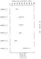
- the method of manufacturing a semiconductor wafer of the present invention is performed in accordance with the process flow shown in FIG. 1.
- an etching process X is inserted between the slicing process A and the chamfering process B of the conventional process flow.
- the etching process X Since the etching process X is performed in order to partially or completely remove a damage layer generated during the slicing process, the etching process X must be performed before a sliced wafer is transported to a subsequent process; i.e., must be performed immediately after the slicing process.
- the chamfering process B, the lapping process C, the mirror-polishing process E, and other processes, which are performed after the etching process X may be modified in the above-described manner. That is, one or more of these processes may be divided into a plurality of stages in order to improve the preciseness of the process or processes, and a heat treatment process, a cleaning process or the like may be added to the above-described processes if needed.
- the sequence of the processes may be modified, or some of the processes may be omitted. Accordingly, the present invention is not limited to the process flow shown in FIG. 1.
- the present invention is especially useful in the case where a wire saw is used in the slicing process for slicing a semiconductor silicon monocrsytalline ingot in order to obtain a disc-shaped semiconductor silicon wafer.
- a wafer obtained through slicing by a wire saw has a deeper distorted layer (stress increasing layer) and therefore a lower strength compared with a wafer obtained through slicing by an ID slicing apparatus, breakage, cracks, chips, and the like are more likely to be generated in a wafer obtained through slicing by a wire saw.
- the present invention can be applied to the case where a semiconductor monocrystalline ingot is sliced by an ID slicing apparatus, because breakage, cracks, chips, and the like are generated in a wafer even when the wafer is obtained through slicing by an ID slicing apparatus.
- the present invention can be effectively applied to the case where a large-diameter semiconductor monocrystalline ingot is sliced by a wire saw, thereby enabling a sliced wafer to be transported to a subsequent process after the strength of the wafer is recovered through partial or complete removal of a damage layer by means of etching performed before the wafer is transported to the subsequent process.
- the etching conditions are determined such that a sliced semiconductor wafer is etched to a depth of several microns or more in order to partially or completely remove the damage layer of the wafer, thereby preventing generation of breakage, cracks, chips, and the like during a subsequent process stemming from damage sustained during the slicing process.
- the concentration, composition, and temperature of an etchant and the time for the etching process can be freely determined so as to adjust an amount of material removed by etching.
- a semiconductor silicon monocrystalline wafer can be etched in acid or alkali.
- Alkali etching can be performed through use of KOH or NaOH at a liquid temperature of 50 - 85° and a concentration of 30 to 85 wt.%.
- Acid etching can be conducted through use of, for example, a mixed acid composed of hydrofluoric acid, nitric acid, and acetic acid (1 : 2-3 : 1-1.5 (volume ratio)) or a mixed acid composed of hydrofluoric acid and nitric acid (1 : 6-10 (volume ratio)), at a liquid temperature of 20 to 50°C.
- the reaction time may be determined in a wide range of 10 second to 5 minutes in accordance with the composition of the etchant.
- Acid etching for silicon is generally performed through use of a mixed acid composed of hydrofluoric acid, nitric acid, and acetic acid.
- a mixed acid composed of hydrofluoric acid and nitric acid which generates a smaller amount of heat, is most preferably used as the etchant in the present invention.
- Measurement was performed to determine how much the strength of a wafer is actually increased by the method of the present invention.
- the breaking strength of each wafer was measured through a three-point bending test. This test was performed according to a method of testing the bending strength of fine ceramics defined in the Japanese Industrial Standard R1601-1981.
- the wafers (Samples 1 and 5) obtained through slicing by the wire saw has a strength smaller than the wafer (Sample 4) obtained through slicing by the ID slicing apparatus. This tendency is more remarkable in the 8-inch wafers than in the 12-inch wafers.
- the present invention is not limited to the above-described embodiment.
- the above-described embodiment is a mere example, and those having the substantially same structure as that described in the appended claims and providing the similar action and effects are included in the scope of the present invention.
- the present invention is not limited thereto and can be applied to the case where a monocrystalline ingot of compound semiconductor such as GaAs, Gap, InP or the like is sliced to manufacture semiconductor wafers.
Landscapes
- Engineering & Computer Science (AREA)
- Mechanical Engineering (AREA)
- Mechanical Treatment Of Semiconductor (AREA)
- Processing Of Stones Or Stones Resemblance Materials (AREA)
Applications Claiming Priority (3)
| Application Number | Priority Date | Filing Date | Title |
|---|---|---|---|
| JP35798296A JP3620683B2 (ja) | 1996-12-27 | 1996-12-27 | 半導体ウエーハの製造方法 |
| JP357982/96 | 1996-12-27 | ||
| JP35798296 | 1996-12-27 |
Publications (2)
| Publication Number | Publication Date |
|---|---|
| EP0850737A2 true EP0850737A2 (de) | 1998-07-01 |
| EP0850737A3 EP0850737A3 (de) | 1999-12-15 |
Family
ID=18456948
Family Applications (1)
| Application Number | Title | Priority Date | Filing Date |
|---|---|---|---|
| EP97310040A Ceased EP0850737A3 (de) | 1996-12-27 | 1997-12-12 | Mehrstufen-Verfahren zur Herstellung von Halbleiterscheiben |
Country Status (4)
| Country | Link |
|---|---|
| US (1) | US5899744A (de) |
| EP (1) | EP0850737A3 (de) |
| JP (1) | JP3620683B2 (de) |
| TW (1) | TW369465B (de) |
Cited By (1)
| Publication number | Priority date | Publication date | Assignee | Title |
|---|---|---|---|---|
| US6214704B1 (en) | 1998-12-16 | 2001-04-10 | Memc Electronic Materials, Inc. | Method of processing semiconductor wafers to build in back surface damage |
Families Citing this family (15)
| Publication number | Priority date | Publication date | Assignee | Title |
|---|---|---|---|---|
| EP0928017B1 (de) * | 1997-12-09 | 2014-09-10 | Shin-Etsu Handotai Co., Ltd. | Herstellungsverfahren für Halbleiterscheiben |
| JP3358549B2 (ja) * | 1998-07-08 | 2002-12-24 | 信越半導体株式会社 | 半導体ウエーハの製造方法ならびにウエーハチャック |
| JP3664593B2 (ja) * | 1998-11-06 | 2005-06-29 | 信越半導体株式会社 | 半導体ウエーハおよびその製造方法 |
| US6596079B1 (en) * | 2000-03-13 | 2003-07-22 | Advanced Technology Materials, Inc. | III-V nitride substrate boule and method of making and using the same |
| DE10064081C2 (de) * | 2000-12-21 | 2002-06-06 | Wacker Siltronic Halbleitermat | Verfahren zur Herstellung einer Halbleiterscheibe |
| DE10159832A1 (de) * | 2001-12-06 | 2003-06-26 | Wacker Siltronic Halbleitermat | Halbleiterscheibe aus Silicium und Verfahren zu deren Herstellung |
| DE10229499B4 (de) * | 2002-04-23 | 2007-05-10 | Fraunhofer-Gesellschaft zur Förderung der angewandten Forschung e.V. | Verfahren zum Bearbeiten eines Wafers |
| DE102005046726B4 (de) * | 2005-09-29 | 2012-02-02 | Siltronic Ag | Nichtpolierte monokristalline Siliziumscheibe und Verfahren zu ihrer Herstellung |
| JP2007204286A (ja) * | 2006-01-31 | 2007-08-16 | Sumco Corp | エピタキシャルウェーハの製造方法 |
| JP2008028259A (ja) * | 2006-07-24 | 2008-02-07 | Mitsubishi Chemicals Corp | 単結晶GaN基板の製造方法 |
| JP2008166805A (ja) * | 2006-12-29 | 2008-07-17 | Siltron Inc | 高平坦度シリコンウェハーの製造方法 |
| JP6032590B2 (ja) * | 2012-04-04 | 2016-11-30 | 株式会社福田結晶技術研究所 | 酸化亜鉛単結晶の製造方法 |
| CN109290874B (zh) * | 2017-07-25 | 2021-02-02 | 北京通美晶体技术有限公司 | 背面有橄榄形凹坑的磷化铟晶片、制法及所用腐蚀液 |
| JP2020188103A (ja) * | 2019-05-14 | 2020-11-19 | 株式会社ディスコ | ウェーハの製造方法 |
| JP7472546B2 (ja) * | 2020-03-03 | 2024-04-23 | 住友金属鉱山株式会社 | 圧電性酸化物単結晶基板の製造方法 |
Family Cites Families (7)
| Publication number | Priority date | Publication date | Assignee | Title |
|---|---|---|---|---|
| GB1206371A (en) * | 1968-03-21 | 1970-09-23 | Westinghouse Brake & Signal | The etching of silicon semiconductor wafers and semiconductor devices incorporating such wafers |
| JPS54110783A (en) * | 1978-02-20 | 1979-08-30 | Hitachi Ltd | Semiconductor substrate and its manufacture |
| DE4304849C2 (de) * | 1992-02-21 | 2000-01-27 | Mitsubishi Electric Corp | Halbleitervorrichtung und Verfahren zur Herstellung einer Halbleitervorrichtung |
| JP2853506B2 (ja) * | 1993-03-24 | 1999-02-03 | 信越半導体株式会社 | ウエーハの製造方法 |
| JP2910507B2 (ja) * | 1993-06-08 | 1999-06-23 | 信越半導体株式会社 | 半導体ウエーハの製造方法 |
| JPH0945643A (ja) * | 1995-07-31 | 1997-02-14 | Komatsu Electron Metals Co Ltd | 半導体ウェハ及びその製造方法 |
| JPH09270400A (ja) * | 1996-01-31 | 1997-10-14 | Shin Etsu Handotai Co Ltd | 半導体ウェーハの製造方法 |
-
1996
- 1996-12-27 JP JP35798296A patent/JP3620683B2/ja not_active Expired - Fee Related
-
1997
- 1997-12-09 TW TW086118508A patent/TW369465B/zh active
- 1997-12-12 EP EP97310040A patent/EP0850737A3/de not_active Ceased
- 1997-12-16 US US08/991,925 patent/US5899744A/en not_active Expired - Fee Related
Cited By (1)
| Publication number | Priority date | Publication date | Assignee | Title |
|---|---|---|---|---|
| US6214704B1 (en) | 1998-12-16 | 2001-04-10 | Memc Electronic Materials, Inc. | Method of processing semiconductor wafers to build in back surface damage |
Also Published As
| Publication number | Publication date |
|---|---|
| JPH10189502A (ja) | 1998-07-21 |
| US5899744A (en) | 1999-05-04 |
| JP3620683B2 (ja) | 2005-02-16 |
| EP0850737A3 (de) | 1999-12-15 |
| TW369465B (en) | 1999-09-11 |
Similar Documents
| Publication | Publication Date | Title |
|---|---|---|
| US5899744A (en) | Method of manufacturing semiconductor wafers | |
| US6376335B1 (en) | Semiconductor wafer manufacturing process | |
| US6239039B1 (en) | Semiconductor wafers processing method and semiconductor wafers produced by the same | |
| KR20060017614A (ko) | 실리콘 웨이퍼의 가공 방법 | |
| CN113692639B (zh) | 磷化铟基板以及磷化铟基板的制造方法 | |
| JP2006222453A (ja) | シリコンウエーハの製造方法及びシリコンウエーハ並びにsoiウエーハ | |
| JP2011003773A (ja) | シリコンウェーハの製造方法 | |
| JP3446616B2 (ja) | シリコンウエーハのエッチング方法およびシリコンウエーハ用エッチング液 | |
| CN86107119A (zh) | 晶片的生产方法 | |
| US20220199770A1 (en) | Indium phosphide substrate and method for producing indium phosphide substrate | |
| US6080641A (en) | Method of manufacturing semiconductor wafer | |
| US6878630B2 (en) | Method of manufacturing a wafer | |
| US5904568A (en) | Method of manufacturing a semiconductor wafer | |
| JP3787485B2 (ja) | 薄板の加工方法 | |
| KR20040060990A (ko) | 접합 웨이퍼의 제조 방법 | |
| US20090311862A1 (en) | Method for manufacturing a semiconductor wafer | |
| JP2005255463A (ja) | サファイア基板とその製造方法 | |
| TWI810847B (zh) | 磷化銦基板 | |
| US6580196B1 (en) | Piezoelectric single crystal wafer | |
| US6576501B1 (en) | Double side polished wafers having external gettering sites, and method of producing same | |
| JPH06248444A (ja) | スパッタリング用ターゲット | |
| JP2003007672A (ja) | シリコン半導体ウェーハのエッチング方法 | |
| JP3491523B2 (ja) | 半導体ウエーハの加工方法 | |
| JP2004043257A (ja) | 化合物半導体ウェハ及びその加工方法 | |
| JPH07283176A (ja) | 半導体ウェハの研磨方法 |
Legal Events
| Date | Code | Title | Description |
|---|---|---|---|
| PUAI | Public reference made under article 153(3) epc to a published international application that has entered the european phase |
Free format text: ORIGINAL CODE: 0009012 |
|
| AK | Designated contracting states |
Kind code of ref document: A2 Designated state(s): DE GB |
|
| AX | Request for extension of the european patent |
Free format text: AL;LT;LV;MK;RO;SI |
|
| PUAL | Search report despatched |
Free format text: ORIGINAL CODE: 0009013 |
|
| AK | Designated contracting states |
Kind code of ref document: A3 Designated state(s): AT BE CH DE DK ES FI FR GB GR IE IT LI LU MC NL PT SE |
|
| AX | Request for extension of the european patent |
Free format text: AL;LT;LV;MK;RO;SI |
|
| RIC1 | Information provided on ipc code assigned before grant |
Free format text: 6B 28D 5/00 A, 6H 01L 21/306 B |
|
| 17P | Request for examination filed |
Effective date: 20000410 |
|
| AKX | Designation fees paid |
Free format text: DE GB |
|
| 17Q | First examination report despatched |
Effective date: 20020607 |
|
| STAA | Information on the status of an ep patent application or granted ep patent |
Free format text: STATUS: THE APPLICATION HAS BEEN REFUSED |
|
| 18R | Application refused |
Effective date: 20040612 |