EP0849176B1 - Dispositif pour emballer des conteneurs dans des boítes, formées à partir d'une ébauche de carton - Google Patents
Dispositif pour emballer des conteneurs dans des boítes, formées à partir d'une ébauche de carton Download PDFInfo
- Publication number
- EP0849176B1 EP0849176B1 EP97830643A EP97830643A EP0849176B1 EP 0849176 B1 EP0849176 B1 EP 0849176B1 EP 97830643 A EP97830643 A EP 97830643A EP 97830643 A EP97830643 A EP 97830643A EP 0849176 B1 EP0849176 B1 EP 0849176B1
- Authority
- EP
- European Patent Office
- Prior art keywords
- packaging apparatus
- bending
- paperboard sheet
- flaps
- assembly
- Prior art date
- Legal status (The legal status is an assumption and is not a legal conclusion. Google has not performed a legal analysis and makes no representation as to the accuracy of the status listed.)
- Expired - Lifetime
Links
Images


Classifications
-
- B—PERFORMING OPERATIONS; TRANSPORTING
- B65—CONVEYING; PACKING; STORING; HANDLING THIN OR FILAMENTARY MATERIAL
- B65B—MACHINES, APPARATUS OR DEVICES FOR, OR METHODS OF, PACKAGING ARTICLES OR MATERIALS; UNPACKING
- B65B5/00—Packaging individual articles in containers or receptacles, e.g. bags, sacks, boxes, cartons, cans, jars
- B65B5/02—Machines characterised by incorporation of means for making the containers or receptacles
- B65B5/024—Machines characterised by incorporation of means for making the containers or receptacles for making containers from preformed blanks
-
- B—PERFORMING OPERATIONS; TRANSPORTING
- B31—MAKING ARTICLES OF PAPER, CARDBOARD OR MATERIAL WORKED IN A MANNER ANALOGOUS TO PAPER; WORKING PAPER, CARDBOARD OR MATERIAL WORKED IN A MANNER ANALOGOUS TO PAPER
- B31B—MAKING CONTAINERS OF PAPER, CARDBOARD OR MATERIAL WORKED IN A MANNER ANALOGOUS TO PAPER
- B31B50/00—Making rigid or semi-rigid containers, e.g. boxes or cartons
- B31B50/26—Folding sheets, blanks or webs
- B31B50/262—Folding sheets, blanks or webs involving folding, leading, or trailing flaps of blanks
-
- B—PERFORMING OPERATIONS; TRANSPORTING
- B31—MAKING ARTICLES OF PAPER, CARDBOARD OR MATERIAL WORKED IN A MANNER ANALOGOUS TO PAPER; WORKING PAPER, CARDBOARD OR MATERIAL WORKED IN A MANNER ANALOGOUS TO PAPER
- B31B—MAKING CONTAINERS OF PAPER, CARDBOARD OR MATERIAL WORKED IN A MANNER ANALOGOUS TO PAPER
- B31B50/00—Making rigid or semi-rigid containers, e.g. boxes or cartons
- B31B50/26—Folding sheets, blanks or webs
- B31B50/52—Folding sheets, blanks or webs by reciprocating or oscillating members, e.g. fingers
- B31B50/54—Folding sheets, blanks or webs by reciprocating or oscillating members, e.g. fingers operating on moving material
-
- B—PERFORMING OPERATIONS; TRANSPORTING
- B65—CONVEYING; PACKING; STORING; HANDLING THIN OR FILAMENTARY MATERIAL
- B65B—MACHINES, APPARATUS OR DEVICES FOR, OR METHODS OF, PACKAGING ARTICLES OR MATERIALS; UNPACKING
- B65B21/00—Packaging or unpacking of bottles
- B65B21/24—Enclosing bottles in wrappers
-
- B—PERFORMING OPERATIONS; TRANSPORTING
- B65—CONVEYING; PACKING; STORING; HANDLING THIN OR FILAMENTARY MATERIAL
- B65B—MACHINES, APPARATUS OR DEVICES FOR, OR METHODS OF, PACKAGING ARTICLES OR MATERIALS; UNPACKING
- B65B43/00—Forming, feeding, opening or setting-up containers or receptacles in association with packaging
- B65B43/12—Feeding flexible bags or carton blanks in flat or collapsed state; Feeding flat bags connected to form a series or chain
- B65B43/14—Feeding individual bags or carton blanks from piles or magazines
- B65B43/16—Feeding individual bags or carton blanks from piles or magazines by grippers
- B65B43/18—Feeding individual bags or carton blanks from piles or magazines by grippers by suction-operated grippers
- B65B43/185—Feeding individual bags or carton blanks from piles or magazines by grippers by suction-operated grippers specially adapted for carton blanks
Definitions
- the present invention relates to an apparatus for packaging products in open or closed boxes, starting from a flat paperboard material.
- An apparatus using such a packaging is disclosed, for example, in the document DE-3 515 248 which illustrates a paperboard sheet which is horizontally arranged at a loading region, where one of the side flaps, horizontally arranged, is preliminarily bent to a vertical position.
- the article assembly is displaced perpendicularly to the side flap toward the base panel and is arranged on said panel.
- the thus formed package is driven toward the side panel, which has been raised at first, and which is arranged perpendicular to the article being packaged inlet direction.
- This apparatus causes a variation of the driving or supplying direction, which greatly hinders a quick operation of the apparatus, since the articles to be packaged must be temporaneously, held in a stop position, which requires a comparatively long time due to the article stop time and the deceleration and acceleration times.
- the above disclosed apparatus requires specifically designed supporting elements in order to lock the flaps against the package, after having inwardly bent said flaps, to allow the glueing material to cure to provide a firm connection.
- the document US 4 571 916 discloses a packaging apparatus in which the paperboard sheets are supplied simultaneously with the articles to be packaged in the same supplying direction.
- the front and rear flaps After having arranged the articles on the base panel, and with the articles and paperboard sheets being driven, the front and rear flaps are upwardly bent through 90° and then are correspondingly bent the side panels to cause said side panels to be vertically arranged.
- Such an apparatus must necessarily comprise specifically designed implements for handling the panels and flaps, which implements are driven along the conveyor belt together with the package, in order to hold each element in its set position, to allow the glue material to properly cure.
- the above apparatus is very complex construction wise and, moreover, its cost is comparatively high.
- the document US 3 844 088 provides a solution in which the finished package is driven away in the same direction in which the paperboard sheet is supplied to the apparatus loading region, fixed bending implements being provided for upwardly bend the side walls or panels.
- the document CH 478 026 discloses a packaging system provided for packaging multiple articles, in which the packaging paperboard sheet is upwardly bent according to a "U" shape, with the flaps or legs raised to a position perpendicular to the driving or supplying direction.
- This apparatus comprises two specifically designed devices for closing the end portions of the package, each of said devices comprising two closing elements for closing the largest panels.
- closing elements in particular, must be designed for movement along the conveyor belt, in order to make the package.
- the packaging process requires a comparatively long time and is very complex.
- the document US 5 149 654 discloses a packaging apparatus in which the side flaps are pre-bent, after having raised the paperboard sheets.
- the base flaps are pre-bent upwardly through 45-80° and are held in this position by means of lever elements, and then the side panels are upwardly bent through 90°; finally, the top and front base flaps are pressed together with the base and rear top flaps of the preceding package and being held in this condition to allow the glue material to cure.
- the document DE-C-4 018 140 discloses a packaging apparatus substantially according to the preamble of Claim 1.
- the aim of the present invention is to overcome the above mentioned drawbacks, by providing an apparatus for packaging products of articles in open or closed boxes, starting from a flat paperboard sheet material, allowing to provide a very high packaging speed, of the order of 60-80 packs or packages per minute, starting from a not pre-glued or pre-processed flat paperboard sheet material.
- a main object of the present invention is to provide such a packaging apparatus allowing to change the paperboard size in a very simple and quick manner, without requiring complex adjustments or substantial modifications of the packaging apparatus.
- Another object of the present invention is to provide such a packaging apparatus, for packaging loose products or articles in open or closed boxes, starting from a flat paperboard sheet material, which allows to greatly reduce the packaging cost, while providing a very high reliability of operation.
- Yet another object of the present invention is to provide such a packaging apparatus for packaging products or articles in open and closed boxes which can be easily made starting from easily commercially available elements and materials and which, moreover, is very competitive from a mere economic standpoint.
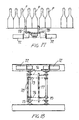
- the apparatus for packaging products or articles in open or closed boxes starting from a flat paperboard sheet material, according to the present invention, and which has been generally indicated by the reference number 1, comprises a bearing framework, generally indicated by the reference number 2, which defines on the top thereof a product "P" supplying line 3 and, at the bottom portion thereof, a paperboard sheet removing assembly, generally indicated by the reference number 4, which is connected, as it will be disclosed in a more detailed manner hereinafter, to the product supplying line.
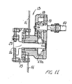
- the rotary paperboard sheet removing device shown in Figures 7 to 12 is substantially constituted by a shaft 10 which transversely supports a plurality of arms 11 in turn supporting at their end portions a plurality of suckers 12.
- the supporting shaft 10 is coupled to driving assemblies 13, which support the end portions of said supporting shaft 10 and are coupled to the shoulders 14 of the apparatus.
- the driving assemblies 13, as is clearly shown in Figure 10, comprise a driven ring gear 15, which is coupled to a bushing 16, which can turn about a first fixed axis 17 parallel to the supporting shaft 10.
- the bushing 16 is rigidly coupled to a supporting body 18, which rotatably supports the supporting shaft 10, on which is keyed a first pinion 19 meshing with a second pinion 19a rigid with the first axis or axle 17.
- the assembly can be clockwise turned and, in particular, the body 18 can be correspondingly turned about the first axis or axle 17, whereas the supporting shaft 10 will turn in an opposite direction about the rotary axis thereof.
- the paperboard sheet is removed from the paperboard sheet stack or magazine and is arranged on the paperboard sheet raising conveyor belt 21.
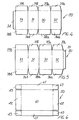
- the paperboard sheets 20, as is schematically shown in Figures 4 to 6, can have any desired configuration.
- Figures 4 and 5 illustrates paperboard sheet for making closed boxes, provided with a bottom 30, adjoining side walls 31 and 32, one of which is coupled to a top element 33.
- a central wing or flap 34 is provided, which is coupled to the top element, or a central flap or wing 35 coupled to a side wall being provided.
- front side flaps or wings 36a and 36b As well as rear side flaps 37a and 37b, whereas to the bottom 30 and to the top element 33 are coupled top flaps and front flaps 38a and 38b, as well as bottom and top rear flaps 39a and 39b.
- a bottom 40 adjoining side walls 41 as well as head walls 42 which can be coupled to the coupling tongues 43, engaged with the side walls.
- the above disclosed rotary paperboard sheet removing device comprises a screw 25, allowing the gear assembly and supporting shaft to be rotated in order to provide a set or desired suction timing.
- the rotary paperboard sheet removing device will allow to obtain a very high production yield, and, in the case of smaller operating speeds, it will be possible to use a modified paperboard sheet removing device; for example in an embodiment shown in Figures 13 and 14 but not according to the invention, a sheet removing device 20. flaps 38a and 38b, as well as bottom and top rear flaps 39a and 39b.
- a bottom 40 adjoining side walls 41 as well as head walls 42 which can be coupled to the coupling tongues 43, engaged with the side walls.
- the above disclosed rotary paperboard sheet removing device comprises a timing screw 25, allowing the gear assembly and supporting shaft to be rotated in order to provide a set or desired suction timing.
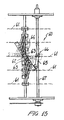
- the rotary paperboard sheet removing device will allow to obtain a very high production yield, and, in the case of smaller operating speeds, it will be possible to use a modified paperboard sheet removing device, shown in Figures 13 and 14 and which has been generally indicated by the reference number 50 and substantially comprising a swinging lever 51 pivoted at the top thereof and supporting bottom suckers 52 engaging with the paperboard sheets, also indicated by 20.
- the suckers 52 are driven and rotated by the driving cam 130 through a small rod 131 so as to arrange the paperboard sheet perpendicular to the paperboard sheet raising direction.
- the lever 51 is driven by a cam assembly 50, operating on an arm 53 engaged with the lever 51, in order to provide a switching from a coupling position with the paperboard sheet stack 20 to the position indicated by the broken line, where the paperboard sheet will be released on the paperboard sheet raising conveyor.
- a product delivery device generally indicated by the reference number 60 is moreover provided, said product delivery device operating for arranging the several products being supplied depending on the size thereof, so as to provide a plurality of product rows.
- side bulkhead elements 61 are provided for practically delimitating the product supplying path, said product being indicated generally by the reference letter "P", and usually comprising cans, bottles or other like elements.
- Said side bulkheads are driven by a control or adjusting assembly comprising a driving bar 62 pivoted at a middle portion thereof and coupled, by connecting levers 63, arranged symmetrically, to the blocks 64 which are in turn connected to the individual bulkheads 61.
- a driving connecting rod 65 To one end of the bar 62 is pivoted a driving connecting rod 65, in turn coupled to a slider 66 movable on a threaded bar 67, which can be driven by a driving motor.
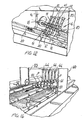
- a separating assembly Downstream of the product delivery device is provided a separating assembly, which can be either of an electronic or of a pneumatic type.
- the electronic separating assembly substantially comprises a first brushless motor 71 and a second brushless motor 72, which brushless motors respectively drive first pinions 73 and second pinions 74.
- Said first and second pinions are respectively coupled to a first chain assembly 75 and a second chain assembly 76, entrained on corresponding transmission pinions, said chains respectively supporting separating comb elements 77 and 78 which are driven under a program control to cause the product P separating comb elements to be engaged between the individual product supplying conveyor belts, the conveyed product being stopped upstream of the separating device.
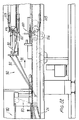
- Figure 19 illustrates a pneumatic separating device, generally indicated by the reference number 80, which comprises a stop comb element 81 driven by a pneumatic piston 82, which is actuated for stopping the upstream product P with respect to separating chains 83 continuously extending and supporting a plurality of bars 84.
- the product will be released and caused to rest on one of said bars, thereby stopping the pushing force provided by the inlet conveyor belt.
- the comb element 81 will be raised to lock the inlet product, whereas the product will advance because of the speed difference between the supplying conveyor belt 86, on which the product are arranged, and the bar 84.
- the bar will be moved away on the front of the product package and will move closer to the rear portion of the preceding package, so as to contact the product and entrain it through the subsequent operating steps.
- Said further operating steps practically comprise the coupling with a raising paperboard sheet 20, so as to cause the product to be arranged on the bottom 30 of the paperboard sheet, which is driven in the same direction, thereby immediately arranging the products on the related paperboard sheets.
- the products arranged on said paperboard sheet are sent to the box forming assembly, generally indicated by the reference number 90, which is provided with side bars 91.
- Said side bars are specifically provided for bending the side walls 31 and 32.
- a top bar for bending the top element, thereby forming the box, is provided.
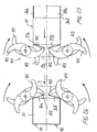
- the side flaps or wings are bent by a side flap bending assembly, indicated by the reference number 100 and made of a disc-like body 101.
- pressing elements having a double cycle configuration indicated by the reference numbers 102 and 103, which owing to the rotary movement about their axes, are so made that the elements 102 will engage with the front side flaps of the box being fed, thereby closing said box.
- the device will be laterally displaced, so as to allow the box to pass therethrough.
- a glue spry is applied, the glue being deposited on the front flaps and rear flaps and, immediately upon applying the glue, the side flaps are bent, as disclosed thereinabove.
- the front flaps are bent by bending levers 110, and the rear flaps are also bent by bending arms 112 coupled to a disc-like element 113.
- the latter is provided with a radially extending lever 114, driven by a piston 115 operating the arms 112 to cause said arms to engage the top and bottom flaps, to cause said flap to be held in contact for a time sufficient for providing a proper closure, whereas, for a normal operation of the apparatus, the front and rear flaps are closed by the front and rear bending arms 110.
- the box In the case of an open tray or box, the box is caused to be longitudinally driven, in parallel to the longest side flaps bending lines.
- the product will be arranged on the base or bottom of the tray, and the side flaps will be turned through 90°.
- the flap bending device Immediately upon having applied the glue spray on the front flaps, the flap bending device is operated in order to transversely bend the flaps through 90° transversely of the flap driving direction, said bending device operating likewise for the rear flaps.
- the box forming device After having closed the front and rear side flaps, the box forming device is operated in order to turn through 90° the base or bottom flaps, i.e. the front and rear flaps, by holding them closed up to the outlet of the apparatus.
- a main advantage of the invention is that it is possible to achieve a very high yield.
Claims (15)
- Dispositif d'emballage (1) pour emballer des produits dans des boítes formées à partir d'un matériau en feuille de carton plat, ledit dispositif d'emballage comprenant une structure de support (2) supportant un assemblage (4) de saisie de feuille de carton pour saisir successivement des feuilles (20) individuelles en carton découpées à transmettre à un transporteur transmettant les feuilles en carton, communiquant avec une voie d'apport (3) de produits (P) à emballer disposée en aval d'un dispositif de séparation de produits (P) recevant lesdits produits à partir d'un dispositif de délivrance de produit, lesdites feuilles de carton étant fournies à ladite voie (3) dans la direction d'alimentation de produit, ledit dispositif comprenant en outre un dispositif formant des boítes contenant un dispositif de pliage pour plier les rabats latéraux (36a, 36b) et les rabats supérieurs et inférieurs (38a, 38b) desdites boítes, caractérisé en ce que ledit assemblage de saisie de feuille de carton comprend un dispositif de saisie de feuille de carton rotatif, incluant un assemblage à engrenage, un arbre de support (10) supportant transversalement des bras (11) munis de ventouses (12) aux extrémités, ledit arbre de support étant couplé aux assemblages d'actionnement engagés avec des parties de support (14) dudit dispositif et comprenant une couronne d'entraínement (15) couplée à une douille rotative (16) tournant autour d'un premier axe fixe (17) parallèle audit arbre de support (10), ladite douille (16) étant couplée de manière rigide à un corps de support (18), supportant de manière rotative ledit arbre de support (10), au-dessus est placé un premier pignon (19), s'engrenant avec un second pignon (19a) rigide avec le premier axe fixe (17) pour faire tourner dans le sens des aiguilles d'une montre ledit assemblage d'actionnement et pour faire tourner dans le sens contraire des aiguilles d'une montre ledit arbre de support.
- Dispositif d'emballage selon la revendication 1, caractérisé en ce que ledit dispositif rotatif (50) de saisie de feuille de carton comprend un levier oscillant (51) pivotant au niveau du sommet de celui-ci et supportant plusieurs ventouses inférieures (52) actionnées de manière rotative par une came d'actionnement (130) à travers une petite tige (52) et engageable avec la première feuille de carton (20) d'une pile de feuilles de carton, ledit levier oscillant (51) étant actionné par un assemblage à came incluant un élément de type bras (53) engagé avec ledit levier oscillant (51) à partir d'une position de couplage dans laquelle ledit levier oscillant (51) rentre en contact avec ladite pile de feuille de carton vers une position de libération dans laquelle ledit levier oscillant (51) libère ladite feuille de carton (20) sur le transporteur élevant la feuille de carton.
- Dispositif d'emballage selon la revendication 1, caractérisé en ce que le dispositif de délivrance de produit (60) contient des éléments latéraux de séparation (61) délimitant la voie d'apport de produits (P), lesdits éléments latéraux de séparation (61) étant actionnés par un dispositif d'ajustement comprenant une barre d'actionnement (62) pivotant au niveau de la partie centrale de celui-ci et couplée, par des leviers de connexion (63), disposés symétriquement, au niveau des blocs de support (64) qui supportent les éléments de séparation (61) individuels, ladite barre pivotant à une extrémité au niveau d'une barre de connexion d'actionnement (65), couplée à une glissière (66) mobile sur une barre filetée (67) disposée transversalement afin de provoquer la rotation de ladite barre d'actionnement (62) avec un déplacement correspondant desdits éléments de séparation (61).
- Dispositif d'emballage selon la revendication 1, caractérisé en ce que ledit dispositif d'emballage comprend en outre un assemblage d'actionnement pour actionner plusieurs petites courroies de transport incluant un système de réglage de petites courroies de transport.
- Dispositif d'emballage selon la revendication 1, caractérisé en ce que ledit dispositif d'emballage comprend un assemblage de séparation électronique (70) incluant un premier et second moteur sans balais (71, 72), actionnant respectivement un premier (73) et un second (74) pignons couplés à un premier (75) et à un second (76) assemblage à chaíne, chaque assemblage à chaíne (75, 76) supportant un élément de séparation de type peigne (77, 78), qui peut être engagé entre lesdits produits (P) et, en particulier, le premier élément de type peigne (77) arrêtant le produit transporté en amont dudit dispositif de séparation et, lorsqu'une taille désirée est atteinte, le second élément de type peigne (78) est engagé pour bloquer le produit en amont.
- Dispositif d'emballage selon la revendication 1, caractérisé en ce que ledit dispositif comprend de plus un dispositif de séparation pneumatique (80), incluant un élément de butée de type peigne (81), actionné par un piston pneumatique (82) qui peut être engagé entre lesdits produits (P) en l'actionnant avec un déplacement perpendiculaire à l'axe d'alimentation desdits produits (P), ledit dispositif comprenant en outre une chaíne de séparation (83) supportant plusieurs barres transversales (84) engagées avec des chaínes fermées en boucle à disposer à l'avant et à l'arrière des groupes de produits séparés.
- Dispositif d'emballage selon la revendication 1, caractérisé en ce que l'assemblage (90) de formation de boítes comprend des barres latérales (91), pour plier les parois latérales (31, 32) et au moins une barre supérieure (92), pour plier l'élément supérieur de la feuille de carton afin de former ladite boíte.
- Dispositif d'emballage selon la revendication 7, caractérisé en ce que ledit assemblage (90) de formation de boítes comprend des éléments latéraux de pression, pour plier lesdites parois latérales.
- Dispositif d'emballage selon la revendication 1, caractérisé en ce que ledit dispositif (100) de pliage de rabats latéraux comprend, avoisinant une région de passage pour ladite feuille de carton, un corps (101) en forme de disque, de là s'étendent des éléments de pression double cycles (102, 103), lesdits éléments de pression étant actionnés de manière rotative afin de s'engager avec les rabats latéraux avants d'une boíte étant fournie et sont disposés latéralement par rapport à ladite boíte afin d'engager successivement les rabats latéraux arrières de ladite boíte.
- Dispositif d'emballage selon la revendication 1, caractérisé en ce que ledit dispositif comprend en outre un assemblage pulvérisateur de colle pour pulvériser de la colle sur les rabats latéraux avant et arrière, avant le pliage des rabats supérieur et inférieur.
- Dispositif d'emballage selon la revendication 1, caractérisé en ce que ledit dispositif d'emballage comprend en outre des leviers de pliage (110) pour plier les rabats supérieur et inférieur avants, ainsi que des bras de pliage (112) pour plier les rabats supérieur et inférieur arrières, lesdits bras de pliage étant couplés à un élément de type disque (113) incluant un levier (114) s'étendant radialement actionné par un piston (115), pour actionner lesdits bras de pliage (112) afin de provoquer ledit engagement desdits bras (112) de pliage avec les rabats supérieurs et les rabats inférieurs lorsque rentrant en contact avec eux durant un temps permettant à ladite colle de durcir.
- Dispositif d'emballage selon la revendication 1, caractérisé en ce que ledit dispositif d'emballage comprend en outre un assemblage de positionnement de noyau de protection pour positionner un noyau de protection entre les produits de type bouteille.
- Dispositif d'emballage selon la revendication 1, caractérisé en ce que ledit dispositif d'emballage comprend en outre des leviers de pliage pour plier les rabats inférieur et supérieur avants, ainsi que des bras de pliage pour plier les rabats supérieurs et inférieurs arrières, lesdits bras de pliage étant couplés à élément de type disque comprenant un levier s'étendant radialement actionné par un piston, pour actionner ledit bras de pliage afin de provoquer l'engagement dudit bras de pliage avec les rabats supérieurs et les rabats inférieurs lorsque rentrant en contact avec eux pendant une durée permettant à la colle de durcir.
- Dispositif d'emballage selon la revendication 1, caractérisé en ce que ledit dispositif d'emballage comprend de plus un assemblage de positionnement de noyau pour positionner un noyau de protection entre les produits de type bouteille.
- Dispositif d'emballage selon la revendication 1, caractérisé en ce que ledit dispositif d'emballage comprend en outre des éléments de type ventouse qui sont actionnés de manière rotative par une came à travers une tige afin de placer la feuille de carton à la perpendiculaire par rapport au plan d'élévation de la feuille de carton.
Priority Applications (1)
| Application Number | Priority Date | Filing Date | Title |
|---|---|---|---|
| EP04004822A EP1471006B1 (fr) | 1996-12-19 | 1997-12-04 | Dispositif pour emballer des conteneurs dans des boîtes, formées à partir d'une ébauche de carton |
Applications Claiming Priority (2)
| Application Number | Priority Date | Filing Date | Title |
|---|---|---|---|
| IT96MI002676A IT1289474B1 (it) | 1996-12-19 | 1996-12-19 | Apparecchiatura per l'imballaggio di prodotti in scatole aperte o chiuse,partendo dal cartone piano |
| ITMI962676 | 1996-12-19 |
Related Child Applications (1)
| Application Number | Title | Priority Date | Filing Date |
|---|---|---|---|
| EP04004822A Division EP1471006B1 (fr) | 1996-12-19 | 1997-12-04 | Dispositif pour emballer des conteneurs dans des boîtes, formées à partir d'une ébauche de carton |
Publications (2)
| Publication Number | Publication Date |
|---|---|
| EP0849176A1 EP0849176A1 (fr) | 1998-06-24 |
| EP0849176B1 true EP0849176B1 (fr) | 2004-03-03 |
Family
ID=11375441
Family Applications (2)
| Application Number | Title | Priority Date | Filing Date |
|---|---|---|---|
| EP04004822A Expired - Lifetime EP1471006B1 (fr) | 1996-12-19 | 1997-12-04 | Dispositif pour emballer des conteneurs dans des boîtes, formées à partir d'une ébauche de carton |
| EP97830643A Expired - Lifetime EP0849176B1 (fr) | 1996-12-19 | 1997-12-04 | Dispositif pour emballer des conteneurs dans des boítes, formées à partir d'une ébauche de carton |
Family Applications Before (1)
| Application Number | Title | Priority Date | Filing Date |
|---|---|---|---|
| EP04004822A Expired - Lifetime EP1471006B1 (fr) | 1996-12-19 | 1997-12-04 | Dispositif pour emballer des conteneurs dans des boîtes, formées à partir d'une ébauche de carton |
Country Status (5)
| Country | Link |
|---|---|
| US (1) | US6038831A (fr) |
| EP (2) | EP1471006B1 (fr) |
| DE (2) | DE69727898T2 (fr) |
| ES (2) | ES2217383T3 (fr) |
| IT (1) | IT1289474B1 (fr) |
Families Citing this family (18)
| Publication number | Priority date | Publication date | Assignee | Title |
|---|---|---|---|---|
| IT1304400B1 (it) * | 1998-10-13 | 2001-03-19 | Azionaria Costruzioni Acma Spa | Metodo e macchina per l'incarto di un prodotto. |
| ITBO20000467A1 (it) * | 2000-07-31 | 2002-01-31 | Prasmatic S R L | Macchina incartonatrice di tipo wrap-around , trsformabile in vassoiatrice , con magazzino dei cartoni posto al di fuori , in linea ed all' |
| DE202004015730U1 (de) * | 2004-10-12 | 2005-09-22 | Krones Ag | Verpackungskarton für eine Gruppe von Behältern |
| ITBO20050537A1 (it) * | 2005-08-25 | 2007-02-26 | Aetna Group Spa | Macchina per l'imballaggio di prodotti in cartoni |
| DE202005014345U1 (de) * | 2005-09-09 | 2007-01-18 | Krones Ag | Vorrichtung zum Verpacken von Artikeln |
| DE102010015865A1 (de) | 2010-03-09 | 2011-09-15 | Krones Ag | Vorrichtung und Verfahren zum Verpacken von Artikeln |
| DE102011016857A1 (de) | 2011-04-13 | 2012-10-18 | Krones Aktiengesellschaft | Vorrichtung zum Verpacken von Artikeln und/oder zum Formen eines Kartons |
| CN104443475B (zh) * | 2014-12-02 | 2016-05-04 | 成都三可实业有限公司 | 一种糖果内盒包装设备 |
| EP3326923A1 (fr) * | 2016-11-24 | 2018-05-30 | Tetra Laval Holdings & Finance S.A. | Appareil de pliage permettant le pliage d'éléments d'emballage sous forme de feuilles |
| DE102017201830A1 (de) | 2017-02-06 | 2018-08-09 | Krones Aktiengesellschaft | Faltvorrichtung, Verpackungsanlage für Artikel und Verfahren zum Falten von Seitenlaschen von Kartonumverpackungen |
| JP7046224B2 (ja) * | 2018-01-29 | 2022-04-01 | グラフィック パッケージング インターナショナル エルエルシー | カートン転回ステーションを備える連続動作包装機 |
| DE102018105269A1 (de) | 2018-03-07 | 2019-09-12 | Krones Aktiengesellschaft | Verpackungsvorrichtung für Artikel und Verfahren zum Bereitstellen von flächigen Verpackungszuschnitten für Artikel |
| AU2020276477A1 (en) * | 2019-05-13 | 2022-01-20 | PunchBowl Automation IP Limited | A fruit packaging tray, apparatus and process |
| CN110525717A (zh) * | 2019-08-16 | 2019-12-03 | 佛山市瀛辉包装机械设备有限公司 | 一种一片式包装纸板双次干胶成型机构 |
| CN110406729A (zh) * | 2019-09-06 | 2019-11-05 | 广东双一智能装备有限公司 | 酸奶自动入盒包装机 |
| FR3100800B1 (fr) | 2019-09-16 | 2021-10-29 | Sidel Packing Solutions | Dispositif et procédé de formage de conteneur par pliage |
| CN112895590A (zh) * | 2021-01-27 | 2021-06-04 | 重庆市永川区华泰印务有限公司 | 一种包装印刷用酒盒生产用翻边装置及其使用方法 |
| CN113306786B (zh) * | 2021-06-18 | 2023-01-06 | 哈工大机器人南昌智能制造研究院 | 一种糕点自动封盒包装方法 |
Family Cites Families (18)
| Publication number | Priority date | Publication date | Assignee | Title |
|---|---|---|---|---|
| US3254470A (en) * | 1962-10-30 | 1966-06-07 | Weyerhaeuser Co | Machine for packaging articles |
| CH460512A (de) * | 1966-06-14 | 1968-07-31 | Fireboard Paper Products Corp | Verfahren und Einrichtung zum Falten, Verschliessen und Siegeln von Kartonschachteln |
| US3527336A (en) * | 1968-02-28 | 1970-09-08 | Associated Millwrights Inc | Guide rail system |
| US3543474A (en) * | 1968-08-26 | 1970-12-01 | Container Corp | Gusset forming machine |
| US3747294A (en) * | 1971-11-08 | 1973-07-24 | Mead Corp | Packaging mechanism |
| US3844088A (en) * | 1973-05-15 | 1974-10-29 | Mcdonough Mfg Co | Packaging and blank handling systems |
| US4034658A (en) * | 1975-10-28 | 1977-07-12 | Olinkraft, Inc. | Tray feeder system |
| US4149452A (en) * | 1977-05-04 | 1979-04-17 | Talarico Lawrence J | Folding and packaging machine |
| DE3307855A1 (de) * | 1983-03-05 | 1984-09-06 | Leifeld und Lemke Maschinenfabrik GmbH & Co KG, 4993 Rahden | Verfahren und vorrichtung zum herstellen von sammelpackungen |
| US4642967A (en) * | 1983-06-27 | 1987-02-17 | The Mead Corporation | Packaging machine |
| US4571916A (en) * | 1983-12-05 | 1986-02-25 | Southern Tool Company | Secondary packaging machine |
| US4854111A (en) * | 1984-10-29 | 1989-08-08 | Roberts Systems, Inc. | Apparatus for conveying and packaging groups of articles |
| US4683705A (en) * | 1985-05-03 | 1987-08-04 | Pemco, Inc. | Method and apparatus for confining wrapped reams of paper sheets in cardboard boxes |
| US4727708A (en) * | 1986-10-06 | 1988-03-01 | Manville Corporation | Wrap-around packaging machine |
| US4793117A (en) * | 1987-05-06 | 1988-12-27 | Standard Knapp, Inc. | Continuous motion tray type packaging machine |
| US4887414A (en) * | 1988-09-06 | 1989-12-19 | Manville Corporation | Article separating and loading apparatus |
| DE3837440A1 (de) * | 1988-11-04 | 1990-05-10 | 4 P Nicolaus Kempten Gmbh | Einrichtung zum verschliessen einer faltschachtel |
| DE4018140C1 (fr) * | 1990-06-06 | 1991-09-26 | Kisters Maschinenbau Gmbh, 4190 Kleve, De |
-
1996
- 1996-12-19 IT IT96MI002676A patent/IT1289474B1/it active IP Right Grant
-
1997
- 1997-12-04 DE DE69727898T patent/DE69727898T2/de not_active Expired - Lifetime
- 1997-12-04 ES ES97830643T patent/ES2217383T3/es not_active Expired - Lifetime
- 1997-12-04 EP EP04004822A patent/EP1471006B1/fr not_active Expired - Lifetime
- 1997-12-04 ES ES04004822T patent/ES2322458T3/es not_active Expired - Lifetime
- 1997-12-04 EP EP97830643A patent/EP0849176B1/fr not_active Expired - Lifetime
- 1997-12-04 US US08/984,837 patent/US6038831A/en not_active Expired - Lifetime
- 1997-12-04 DE DE69739273T patent/DE69739273D1/de not_active Expired - Lifetime
Also Published As
| Publication number | Publication date |
|---|---|
| ES2322458T3 (es) | 2009-06-22 |
| EP1471006A3 (fr) | 2007-06-20 |
| EP1471006B1 (fr) | 2009-02-18 |
| DE69739273D1 (de) | 2009-04-02 |
| ITMI962676A0 (it) | 1996-12-19 |
| DE69727898D1 (de) | 2004-04-08 |
| EP1471006A2 (fr) | 2004-10-27 |
| US6038831A (en) | 2000-03-21 |
| DE69727898T2 (de) | 2005-03-03 |
| ITMI962676A1 (it) | 1998-06-19 |
| IT1289474B1 (it) | 1998-10-15 |
| ES2217383T3 (es) | 2004-11-01 |
| EP0849176A1 (fr) | 1998-06-24 |
Similar Documents
| Publication | Publication Date | Title |
|---|---|---|
| EP0849176B1 (fr) | Dispositif pour emballer des conteneurs dans des boítes, formées à partir d'une ébauche de carton | |
| EP2024234B1 (fr) | Systeme d'emballage avec carrousel de chargement | |
| US4066009A (en) | Method for opening and erecting cartons | |
| CZ286640B6 (cs) | Zařízení pro podávání kusových polotovarů ze zásobníku, zejména obalů | |
| US20080034709A1 (en) | Packaging machine and method of forming an insert | |
| US20030000182A1 (en) | Packaging machine and apparatus for wraparound cartons | |
| WO1989009726A1 (fr) | Procede et unite d'encartonnage vertical | |
| US6050060A (en) | Unit and method for forming a group of products on a wrapping machine | |
| US4709538A (en) | Apparatus for feeding and opening a beverage carrier | |
| EP0994026B1 (fr) | Proçédé et machine pour emballer un produit | |
| GB2161131A (en) | Sleeve carton end panel and flap folding and sealing assembly | |
| US3083510A (en) | Method and machine for packaging articles | |
| US3303631A (en) | Machine for and method of applying carriers to containers | |
| US7093408B2 (en) | Packaging machine and method of forming a carton | |
| WO2010030844A1 (fr) | Appareil et procédé d’emballage | |
| EP2343244A2 (fr) | Machine pour le conditionnement d'articles | |
| EP1028894B1 (fr) | Mecanisme de redressement d'ebauche de carton | |
| CA2373431C (fr) | Machine d'emballage et procede de formation de carton | |
| US6381927B1 (en) | Method and apparatus for folding carton flaps in a packaging machine | |
| EP0994027B1 (fr) | Procédé et machine pour emballer un groupe d'objets | |
| US4682975A (en) | Machine and method for setting-up basket style article carriers | |
| EP1240082B1 (fr) | Encartonneuse et dispositif pour cartons wrap-around | |
| WO2002053460A1 (fr) | Machine d'emballage et procede de positionnement d'un element d'insertion |
Legal Events
| Date | Code | Title | Description |
|---|---|---|---|
| PUAI | Public reference made under article 153(3) epc to a published international application that has entered the european phase |
Free format text: ORIGINAL CODE: 0009012 |
|
| AK | Designated contracting states |
Kind code of ref document: A1 Designated state(s): CH DE ES FR GB LI |
|
| AX | Request for extension of the european patent |
Free format text: AL;LT;LV;MK;RO;SI |
|
| 17P | Request for examination filed |
Effective date: 19980617 |
|
| AKX | Designation fees paid |
Free format text: CH DE ES FR GB LI |
|
| RBV | Designated contracting states (corrected) |
Designated state(s): CH DE ES FR GB LI |
|
| 17Q | First examination report despatched |
Effective date: 20020624 |
|
| GRAP | Despatch of communication of intention to grant a patent |
Free format text: ORIGINAL CODE: EPIDOSNIGR1 |
|
| GRAS | Grant fee paid |
Free format text: ORIGINAL CODE: EPIDOSNIGR3 |
|
| GRAA | (expected) grant |
Free format text: ORIGINAL CODE: 0009210 |
|
| AK | Designated contracting states |
Kind code of ref document: B1 Designated state(s): CH DE ES FR GB LI |
|
| REG | Reference to a national code |
Ref country code: GB Ref legal event code: FG4D |
|
| REG | Reference to a national code |
Ref country code: CH Ref legal event code: EP |
|
| REF | Corresponds to: |
Ref document number: 69727898 Country of ref document: DE Date of ref document: 20040408 Kind code of ref document: P |
|
| REG | Reference to a national code |
Ref country code: CH Ref legal event code: NV Representative=s name: BOVARD AG PATENTANWAELTE |
|
| REG | Reference to a national code |
Ref country code: ES Ref legal event code: FG2A Ref document number: 2217383 Country of ref document: ES Kind code of ref document: T3 |
|
| ET | Fr: translation filed | ||
| PLBE | No opposition filed within time limit |
Free format text: ORIGINAL CODE: 0009261 |
|
| STAA | Information on the status of an ep patent application or granted ep patent |
Free format text: STATUS: NO OPPOSITION FILED WITHIN TIME LIMIT |
|
| 26N | No opposition filed |
Effective date: 20041206 |
|
| REG | Reference to a national code |
Ref country code: CH Ref legal event code: PFA Owner name: SMI S.P.A. Free format text: SMI S.P.A.#VIA PIAZZALUNGA, 30#24015 SAN GIOVANNI BIANCO (BERGAMO) (IT) -TRANSFER TO- SMI S.P.A.#VIA PIAZZALUNGA, 30#24015 SAN GIOVANNI BIANCO (BERGAMO) (IT) |
|
| PGFP | Annual fee paid to national office [announced via postgrant information from national office to epo] |
Ref country code: ES Payment date: 20141124 Year of fee payment: 18 Ref country code: DE Payment date: 20141213 Year of fee payment: 18 Ref country code: GB Payment date: 20141201 Year of fee payment: 18 Ref country code: CH Payment date: 20141204 Year of fee payment: 18 |
|
| PGFP | Annual fee paid to national office [announced via postgrant information from national office to epo] |
Ref country code: FR Payment date: 20141224 Year of fee payment: 18 |
|
| REG | Reference to a national code |
Ref country code: DE Ref legal event code: R119 Ref document number: 69727898 Country of ref document: DE |
|
| REG | Reference to a national code |
Ref country code: CH Ref legal event code: PL |
|
| GBPC | Gb: european patent ceased through non-payment of renewal fee |
Effective date: 20151204 |
|
| REG | Reference to a national code |
Ref country code: FR Ref legal event code: ST Effective date: 20160831 |
|
| PG25 | Lapsed in a contracting state [announced via postgrant information from national office to epo] |
Ref country code: DE Free format text: LAPSE BECAUSE OF NON-PAYMENT OF DUE FEES Effective date: 20160701 Ref country code: LI Free format text: LAPSE BECAUSE OF NON-PAYMENT OF DUE FEES Effective date: 20151231 Ref country code: GB Free format text: LAPSE BECAUSE OF NON-PAYMENT OF DUE FEES Effective date: 20151204 Ref country code: CH Free format text: LAPSE BECAUSE OF NON-PAYMENT OF DUE FEES Effective date: 20151231 |
|
| PG25 | Lapsed in a contracting state [announced via postgrant information from national office to epo] |
Ref country code: FR Free format text: LAPSE BECAUSE OF NON-PAYMENT OF DUE FEES Effective date: 20151231 |
|
| REG | Reference to a national code |
Ref country code: ES Ref legal event code: FD2A Effective date: 20170127 |
|
| PG25 | Lapsed in a contracting state [announced via postgrant information from national office to epo] |
Ref country code: ES Free format text: LAPSE BECAUSE OF NON-PAYMENT OF DUE FEES Effective date: 20151205 |