EP0847799B1 - Rührorgan - Google Patents
Rührorgan Download PDFInfo
- Publication number
- EP0847799B1 EP0847799B1 EP97121866A EP97121866A EP0847799B1 EP 0847799 B1 EP0847799 B1 EP 0847799B1 EP 97121866 A EP97121866 A EP 97121866A EP 97121866 A EP97121866 A EP 97121866A EP 0847799 B1 EP0847799 B1 EP 0847799B1
- Authority
- EP
- European Patent Office
- Prior art keywords
- stirring
- stirring element
- element according
- support disc
- hub
- Prior art date
- Legal status (The legal status is an assumption and is not a legal conclusion. Google has not performed a legal analysis and makes no representation as to the accuracy of the status listed.)
- Expired - Lifetime
Links
- 238000003756 stirring Methods 0.000 claims abstract description 60
- 239000007788 liquid Substances 0.000 claims abstract description 6
- 230000002093 peripheral effect Effects 0.000 claims abstract description 3
- 239000006185 dispersion Substances 0.000 abstract description 3
- 238000009827 uniform distribution Methods 0.000 abstract 1
- 241000237942 Conidae Species 0.000 description 2
- 238000005452 bending Methods 0.000 description 1
- 230000006735 deficit Effects 0.000 description 1
- 230000000694 effects Effects 0.000 description 1
- 238000003958 fumigation Methods 0.000 description 1
- 239000002184 metal Substances 0.000 description 1
- 238000000034 method Methods 0.000 description 1
Images
Classifications
-
- B—PERFORMING OPERATIONS; TRANSPORTING
- B01—PHYSICAL OR CHEMICAL PROCESSES OR APPARATUS IN GENERAL
- B01F—MIXING, e.g. DISSOLVING, EMULSIFYING OR DISPERSING
- B01F27/00—Mixers with rotary stirring devices in fixed receptacles; Kneaders
- B01F27/05—Stirrers
- B01F27/11—Stirrers characterised by the configuration of the stirrers
- B01F27/115—Stirrers characterised by the configuration of the stirrers comprising discs or disc-like elements essentially perpendicular to the stirrer shaft axis
- B01F27/1152—Stirrers characterised by the configuration of the stirrers comprising discs or disc-like elements essentially perpendicular to the stirrer shaft axis with separate elements other than discs fixed on the discs, e.g. vanes fixed on the discs
-
- B—PERFORMING OPERATIONS; TRANSPORTING
- B01—PHYSICAL OR CHEMICAL PROCESSES OR APPARATUS IN GENERAL
- B01F—MIXING, e.g. DISSOLVING, EMULSIFYING OR DISPERSING
- B01F23/00—Mixing according to the phases to be mixed, e.g. dispersing or emulsifying
- B01F23/20—Mixing gases with liquids
- B01F23/23—Mixing gases with liquids by introducing gases into liquid media, e.g. for producing aerated liquids
- B01F23/233—Mixing gases with liquids by introducing gases into liquid media, e.g. for producing aerated liquids using driven stirrers with completely immersed stirring elements
-
- B—PERFORMING OPERATIONS; TRANSPORTING
- B01—PHYSICAL OR CHEMICAL PROCESSES OR APPARATUS IN GENERAL
- B01F—MIXING, e.g. DISSOLVING, EMULSIFYING OR DISPERSING
- B01F23/00—Mixing according to the phases to be mixed, e.g. dispersing or emulsifying
- B01F23/20—Mixing gases with liquids
- B01F23/23—Mixing gases with liquids by introducing gases into liquid media, e.g. for producing aerated liquids
- B01F23/233—Mixing gases with liquids by introducing gases into liquid media, e.g. for producing aerated liquids using driven stirrers with completely immersed stirring elements
- B01F23/2336—Mixing gases with liquids by introducing gases into liquid media, e.g. for producing aerated liquids using driven stirrers with completely immersed stirring elements characterised by the location of the place of introduction of the gas relative to the stirrer
- B01F23/23362—Mixing gases with liquids by introducing gases into liquid media, e.g. for producing aerated liquids using driven stirrers with completely immersed stirring elements characterised by the location of the place of introduction of the gas relative to the stirrer the gas being introduced under the stirrer
-
- B—PERFORMING OPERATIONS; TRANSPORTING
- B01—PHYSICAL OR CHEMICAL PROCESSES OR APPARATUS IN GENERAL
- B01F—MIXING, e.g. DISSOLVING, EMULSIFYING OR DISPERSING
- B01F33/00—Other mixers; Mixing plants; Combinations of mixers
- B01F33/80—Mixing plants; Combinations of mixers
- B01F33/82—Combinations of dissimilar mixers
- B01F33/822—Combinations of dissimilar mixers with moving and non-moving stirring devices in the same receptacle
-
- B—PERFORMING OPERATIONS; TRANSPORTING
- B01—PHYSICAL OR CHEMICAL PROCESSES OR APPARATUS IN GENERAL
- B01F—MIXING, e.g. DISSOLVING, EMULSIFYING OR DISPERSING
- B01F27/00—Mixers with rotary stirring devices in fixed receptacles; Kneaders
- B01F27/05—Stirrers
- B01F27/11—Stirrers characterised by the configuration of the stirrers
- B01F27/112—Stirrers characterised by the configuration of the stirrers with arms, paddles, vanes or blades
- B01F27/1125—Stirrers characterised by the configuration of the stirrers with arms, paddles, vanes or blades with vanes or blades extending parallel or oblique to the stirrer axis
-
- B—PERFORMING OPERATIONS; TRANSPORTING
- B01—PHYSICAL OR CHEMICAL PROCESSES OR APPARATUS IN GENERAL
- B01F—MIXING, e.g. DISSOLVING, EMULSIFYING OR DISPERSING
- B01F27/00—Mixers with rotary stirring devices in fixed receptacles; Kneaders
- B01F27/05—Stirrers
- B01F27/11—Stirrers characterised by the configuration of the stirrers
- B01F27/115—Stirrers characterised by the configuration of the stirrers comprising discs or disc-like elements essentially perpendicular to the stirrer shaft axis
Definitions
- the invention relates to an agitator, in particular a Fumigation stirrer for stirring liquids, which a gas, for example air, is supplied according to Preamble of claim 1.
- a gas for example air
- a stirrer of the type mentioned above is known from US-A-5,198,156 or US-A-4,779,990.
- one of the The gas supplied to the stirring liquid is as small as possible Bubbles dispersed to a large surface for the Mass transfer between the gas and the liquid too create.
- Such a gassing stirrer usually includes one Disc stirrers with stirring blades and an annular one Gas distributor, circular along its apex Holes are formed that keep the gas rotating Feed disc stirrer, the shear effect of which Gas is further dispersed.
- the stirrer By the rotational movement the stirrer is created on the back of the Stirring blades a negative pressure, which is there to form Gas cushion leads.
- These gas cushions give the stirring blades a more aerodynamic contour, which is in a sharp drop in performance at a given speed expresses.
- the invention is based on the object Stirring device to create these disadvantages mentioned above at least essentially eliminated.
- a stirring element is provided for this purpose, which has the features of claim 1.
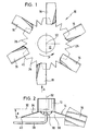
- FIG. 1 shows a top view of a stirring element 10 with a hub 12 for fastening the stirring element 10 to a not shown Agitator shaft.
- the Agitator 10 has a central axis 32. This rotates during operation Stirring element 10 in the direction of arrow P around the stirrer axis central axis 32.
- the level of rotation or stirring level 30 lies transversely to the stirring axis 32.
- the support disk 14 is conical, the fictitious cone tip expediently in the Stirring axis 32 lies.
- the support disk 14 can also in other ways, for example graded, conical or curved, as long as below it the cavity 36 is formed.
- FIG. 2 shows, there is a supply pipe 28 for the gas supply in the Cavity 36 introduced, the mouth 38 conveniently below the fictitious cone tip and concentric to the stirring axis 32 lies.
- the support plate 14 is on its outer Circumferential edge 40 with, in particular, triangular prongs 26 provided that apart from the attachment points of the stirring blades 16 along the entire circumference of the support disk 14 run.
- the prongs 26 are expediently in the surface of the cone shell 34 (or form part of this), they but can also up or down relative to the cone shell 34 be turned.
- prongs 26 forming a ring of peaks are uniform Gas leakage and improve the dispersion of the over the Feed pipe 28 in the cavity 36 introduced gas, or with in other words, they help break up the gas bubbles.
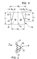
- Figure 3 shows a plan view of the blank, that is given sheet metal blank of a stirring blade 16 before this in his Operating form is bent.
- the blank 42 is approximately trapezoidal in shape and has on its outside (related to the later working position) one Width B1 of, for example, 40mm and one on the inside Width B2 of, for example, 50mm.
- the radial length L1 of the Blank 42 is, for example, 37 to 38mm. (Of course the invention is not based on this only as an example mentioned dimensions.)
- the blank 42 becomes wedge-shaped along its center line 44 bent such that the two legs 18 and 20 of the wedge enclose an angle ⁇ , as shown in FIG. 4.
- the wedge angle ⁇ expediently lies approximately in the range from 45 ° to 75 °, and he is preferably about 60 °.
- End sections 22 and 24 of the two legs 18 and 20 are longitudinal of the bending lines 46 and 48 and based on that in FIG. 3 shown position of the blank 42 upwards by an angle ⁇ ( Figure 4) bent.
- the angle ⁇ between the respective end section 22, 24 and its associated leg 18, 20 is expediently in Range from about 120 ° to 160 ° and is preferably about 140 °.
- the end sections 22, 24 are essentially triangular formed, and their width increases in the radial direction from the The outside of the stirring blade is towards the inside of the stirring blade.
- On the inside of the stirring blade 50 in this example is the width B3 End section 22, 24 about 12.5 mm, but this dimension only is an example to which the invention is not limited.
- the Length L2 of the end sections 22, 24, measured from the inside of the stirring blade 50 off, can expediently about two thirds to amount to three quarters of the radial length L1 of the stirring blade 16, while the width B3 of the end portions 22, 24 on the inside of the stirring blade 50 about 20% to 30%, preferably about 25%, the total width B2 of the stirring blade blank 42 can be.
Landscapes
- Chemical & Material Sciences (AREA)
- Chemical Kinetics & Catalysis (AREA)
- Mixers Of The Rotary Stirring Type (AREA)
- Mixers With Rotating Receptacles And Mixers With Vibration Mechanisms (AREA)
Description
- Fig. 1
- eine schematische Draufsicht auf das neuerungsgemäße Rührorgan.
- Fig. 2
- schematisch einen Längsschnitt durch die Mittelachse des Rührorganes nach Figur 1,
- Fig. 3
- eine Draufsicht auf ein Rührblatt des Rührorganes im noch ebenen, ungebogenen Zustand, und
- Fig. 4
- schematisch eine Ansicht des fertig bearbeiteten Rührblattes in Richtung des Pfeiles A in Figur 1.
Claims (11)
- Rührorgan, insbesondere Begasungs-Rührorgan zum Rühren von Flüssigkeiten, denen ein Gas, zum Beispiel Luft, zugeführt wird, mit einer Nabe (12) zur Befestigung an einer Rührwelle, einer mit der Nabe (12) verbundenen Tragscheibe (14), an deren Umfangsrand eine Mehrzahl von Rührblättern (16) angebracht ist, die jeweils in Bewegungsrichtung keilförmig abgewinkelt ausgebildet sind, dadurch gekennzeichnet, daß die radial inneren Endabschnitte (22, 24) der beiden Schenkel (18, 20) des Rührblattes (16) relativ zu den Schenkeln (18, 20) nach außen abgewinkelt sind.
- Rührorgan nach Anspruch 1, dadurch gekennzeichnet, daß der Winkel (β) zwischen dem jeweiligen Schenkel (18) bzw. (20) und seinem abgewinkelten Endabschnitt (22 bzw. 24) etwa 120° bis 160°, vorzugsweise etwa 140° beträgt.
- Rührorgan nach Anspruch 1 oder 2, dadurch gekennzeichnet, daß die Endabschnitte (22, 24) dreieckförmig ausgebildet sind und ihre Breite radial von außen nach innen zunimmt.
- Rührorgan nach einem der Ansprüche 1 bs 3, dadurch gekennzeichnet, daß die Endabschnitte (22, 24) dreieckförmig ausgebildet sind und ihre Breite radial von außen nach innen zunimmt.
- Rührorgan nach einem der vorangehenden Ansprüche, dadurch gekennzeichnet, daß der Keilwinkel (α) des Rührblattes (16) etwa 45° bis 75°, vorzugsweise etwa 60° beträgt.
- Rührorgan nach einem der vorangehenden Ansprüche, dadurch gekennzeichnet, daß die Tragscheibe (14) für die Rührblätter (16) von der Nabe (12) weg nach unten abgewinkelt oder abgebogen ist derart, daß unter ihr ein Hohlraum (36) gebildet ist.
- Rührorgan nach Anspruch 6, dadurch gekennzeichnet, daß die Tragscheibe (14) gewölbt, abgestuft, konisch oder insbesondere kegelförmig ausgebildet ist.
- Rührorgan nach Anspruch 7, dadurch gekennzeichnet, daß der Kegelöffnungswinkel (γ) der Tragscheibe (14) etwa 140° bis 150°, insbesondere etwa 146° beträgt.
- Rührorgan nach Anspruch 6, 7 oder 8, dadurch gekennzeichnet, daß die Tragscheibe (14) an ihrem Außenrand (40) mit insbesondere dreieckförmigen Zacken (26) versehen ist.
- Rührorgan nach Anspruch 9, dadurch gekennzeichnet, daß die Zacken (26) in der Kegelmantelfläche (34) liegen oder relativ zu dieser abgewinkelt sind.
- Rührorgan nach Anspruch 1 und 6, dadurch gekennzeichnet, daß das Gas mittels eines Zufuhrrohres (28) in den Hohlraum (36) unter der kegeligen Tragscheibe (14) einführbar ist.
Applications Claiming Priority (2)
| Application Number | Priority Date | Filing Date | Title |
|---|---|---|---|
| DE29621683U DE29621683U1 (de) | 1996-12-13 | 1996-12-13 | Rührorgan |
| DE29621683U | 1996-12-13 |
Publications (2)
| Publication Number | Publication Date |
|---|---|
| EP0847799A1 EP0847799A1 (de) | 1998-06-17 |
| EP0847799B1 true EP0847799B1 (de) | 2000-09-20 |
Family
ID=8033262
Family Applications (1)
| Application Number | Title | Priority Date | Filing Date |
|---|---|---|---|
| EP97121866A Expired - Lifetime EP0847799B1 (de) | 1996-12-13 | 1997-12-11 | Rührorgan |
Country Status (5)
| Country | Link |
|---|---|
| US (1) | US5904423A (de) |
| EP (1) | EP0847799B1 (de) |
| AT (1) | ATE196432T1 (de) |
| DE (2) | DE29621683U1 (de) |
| DK (1) | DK0847799T3 (de) |
Families Citing this family (18)
| Publication number | Priority date | Publication date | Assignee | Title |
|---|---|---|---|---|
| JP3695033B2 (ja) * | 1997-01-20 | 2005-09-14 | 味の素株式会社 | 撹拌翼 |
| US20040188334A1 (en) * | 1998-09-28 | 2004-09-30 | Mcwhirter John R. | Novel biochemical oxidation system |
| US6190033B1 (en) | 1999-04-09 | 2001-02-20 | Pfaulder, Inc. | High gas dispersion efficiency glass coated impeller |
| DE602006015446D1 (de) * | 2005-03-21 | 2010-08-26 | Bp Corp North America Inc | Verfahren und vorrichtung zur herstellung aromatischer carboxyl-säuren einschliesslich reiner formen davon |
| EP1776999A1 (de) * | 2005-10-21 | 2007-04-25 | Abb Research Ltd. | Ein Mischer |
| DE102007001711A1 (de) | 2007-01-11 | 2008-07-17 | EKATO Rühr- und Mischtechnik GmbH | Rühranordnung mit einem Rührorgan und einer Begasungseinrichtung |
| US20080199321A1 (en) * | 2007-02-16 | 2008-08-21 | Spx Corporation | Parabolic radial flow impeller with tilted or offset blades |
| CN101778664B (zh) * | 2007-08-09 | 2013-07-24 | 英文特环境及工艺股份公司 | 用于活性污泥的搅拌设备 |
| MX2010006954A (es) * | 2007-12-21 | 2010-10-07 | Philadelphia Mixing Solutions Ltd | Impulsor de capa de gas. |
| DE102010004206A1 (de) * | 2009-06-08 | 2010-12-09 | EKATO Rühr- und Mischtechnik GmbH | Rühranrodnung |
| US8882470B2 (en) * | 2011-01-07 | 2014-11-11 | Fritz Unger | Rotor for a wind power generator |
| US9108170B2 (en) | 2011-11-24 | 2015-08-18 | Li Wang | Mixing impeller having channel-shaped vanes |
| CA156862S (en) * | 2013-12-04 | 2015-01-14 | Outotec Finland Oy | Impeller for hydrometallurgical mixer |
| RU2687489C1 (ru) | 2013-12-18 | 2019-05-14 | Бипи Корпорейшен Норт Америка Инк. | Улучшенный способ и устройство для производства ароматических карбоновых кислот |
| CN106573209B (zh) | 2014-08-13 | 2020-01-03 | 维尔萨利斯股份公司 | 转子以及搅拌设备 |
| CN105854664B (zh) * | 2016-04-27 | 2017-12-29 | 江南大学 | 一种装配扇环型凹面叶片的气液分散搅拌器装置 |
| US12390773B2 (en) | 2019-08-15 | 2025-08-19 | Nov Process & Flow Technologies Us, Inc. | Gas dispersion system |
| USD953388S1 (en) * | 2019-08-30 | 2022-05-31 | Kazuo Sato | Food industry machine |
Family Cites Families (15)
| Publication number | Priority date | Publication date | Assignee | Title |
|---|---|---|---|---|
| US1579355A (en) * | 1923-06-11 | 1926-04-06 | William E Greenawalt | Apparatus for treating liquids with gases |
| US2043940A (en) * | 1933-01-11 | 1936-06-09 | Naamlooze Vennottschap Ind Mij | Apparatus for the manufacture of yeast |
| US2308751A (en) * | 1941-04-24 | 1943-01-19 | Chicago By Products Corp | Means for dispersing one fluid in another fluid |
| US2384952A (en) * | 1942-09-02 | 1945-09-18 | Mixing Equipment Co Inc | Dispersing agitator |
| US3100628A (en) * | 1962-03-05 | 1963-08-13 | Jr Robert W Norris | Dispersing apparatus |
| GB1211270A (en) * | 1968-12-24 | 1970-11-04 | Nestle Sa | Agitation device |
| DE2300205A1 (de) * | 1972-01-05 | 1973-07-26 | Hitachi Ltd | Vorrichtung zum in-beruehrung-bringen von gasen und fluessigkeiten |
| DE2207144A1 (de) * | 1972-02-16 | 1973-08-30 | Schoeller Bleckmann Stahlwerke | Begasungsvorrichtung mit fluegelartigen ruehrarmen |
| US4421414A (en) * | 1980-03-05 | 1983-12-20 | General Signal | High efficiency mixing method |
| DE3519520A1 (de) | 1985-05-31 | 1986-12-04 | Durst Franz | Wirbelkegelruehrer & begaser vorrichtung zum begasen und umwaelzen von fluessigkeiten in becken |
| SE461444B (sv) | 1985-11-21 | 1990-02-19 | Boerje Skaanberg | Impellerapparat foer omroerning av vaetska under dispergering av gas daeri |
| US5198156A (en) * | 1986-02-17 | 1993-03-30 | Imperial Chemical Industries Plc | Agitators |
| SU1414438A1 (ru) * | 1986-07-07 | 1988-08-07 | Предприятие П/Я Р-6956 | Мешалка |
| US5006283A (en) * | 1988-10-06 | 1991-04-09 | General Signal Corporation | Mixing system for dispersing a compressible fluid such as gas into liquid in a vessel |
| EP0441505A1 (de) | 1990-02-05 | 1991-08-14 | Imperial Chemical Industries Plc | Rührwerk |
-
1996
- 1996-12-13 DE DE29621683U patent/DE29621683U1/de not_active Expired - Lifetime
-
1997
- 1997-12-10 US US08/988,449 patent/US5904423A/en not_active Expired - Lifetime
- 1997-12-11 AT AT97121866T patent/ATE196432T1/de active
- 1997-12-11 DK DK97121866T patent/DK0847799T3/da active
- 1997-12-11 EP EP97121866A patent/EP0847799B1/de not_active Expired - Lifetime
- 1997-12-11 DE DE59702379T patent/DE59702379D1/de not_active Expired - Lifetime
Also Published As
| Publication number | Publication date |
|---|---|
| EP0847799A1 (de) | 1998-06-17 |
| DE59702379D1 (de) | 2000-10-26 |
| US5904423A (en) | 1999-05-18 |
| ATE196432T1 (de) | 2000-10-15 |
| DK0847799T3 (da) | 2001-01-29 |
| DE29621683U1 (de) | 1997-02-13 |
Similar Documents
| Publication | Publication Date | Title |
|---|---|---|
| EP0847799A1 (de) | Rührorgan | |
| DE3601680A1 (de) | Verfahren und vorrichtung zum kontinuierlichen mischen und kneten pulverfoermiger koerper wie von pulverisierter kohle und oelkoks oder dergleichen zur herstellung einer aufschlaemmung hieraus | |
| DE19959348A1 (de) | Schleifscheibe für die Verwendung in einer Schleifvorrichtung | |
| EP2771581B1 (de) | Axialventilatorrad | |
| DE1205058B (de) | Vorrichtung zum Umwaelzen und Belueften einer Fluessigkeit in einem Behaelter | |
| DE2709309A1 (de) | Vorrichtung zur zufuehrung fliessfaehiger feststoffe | |
| EP1475145A2 (de) | Rührorgan | |
| DE3617175A1 (de) | Einrichtung zum passieren, insbesondere granulieren und/oder sieben eines gutes | |
| DE2546149C2 (de) | Schneideinrichtung zum Zerkleinern von festen Nahrungsmitteln | |
| DE2165828C3 (de) | Vorrichtung zum Aufteilen einer Teilchenmasse in Teilstrome | |
| DE102013018690A1 (de) | Rühreinrichtung für einen Fermenter einer Biogasanlage und Verfahren zur Herstellung einer Rühreinrichtung | |
| DE1243335B (de) | Einrichtung zum ununterbrochenen Aufbereiten von Formsand fuer Giessereien | |
| DE872198C (de) | Ruehr- und Mischfluegel, insbesondere zum Mischen von Brennereimaischen | |
| WO2004030498A2 (de) | Schlagscheibe für küchengeräte | |
| EP4062809A1 (de) | Milchschäumer und heissgetränkezubereitungseinrichtung | |
| EP1542525B1 (de) | Schleuderdüngerstreuer | |
| DE3111124C2 (de) | ||
| DE19817742C2 (de) | Schleuderstreuer | |
| DE3708359A1 (de) | Vorrichtung zum aufspannen eines kreissaegeblattes | |
| DE69811885T2 (de) | Schälgerät für knolle | |
| DE1582316A1 (de) | Maehmaschine | |
| DE7934681U1 (de) | Kuechenmaschine | |
| CH617103A5 (de) | ||
| DE2823515A1 (de) | Begasungsvorrichtung | |
| DE2933784A1 (de) | Jaucheruehrgeraet |
Legal Events
| Date | Code | Title | Description |
|---|---|---|---|
| PUAI | Public reference made under article 153(3) epc to a published international application that has entered the european phase |
Free format text: ORIGINAL CODE: 0009012 |
|
| AK | Designated contracting states |
Kind code of ref document: A1 Designated state(s): AT CH DE DK FR GB IT LI NL |
|
| AX | Request for extension of the european patent |
Free format text: AL;LT;LV;MK;RO;SI |
|
| 17P | Request for examination filed |
Effective date: 19981215 |
|
| AKX | Designation fees paid |
Free format text: AT CH DE DK FR GB IT LI NL |
|
| RBV | Designated contracting states (corrected) |
Designated state(s): AT CH DE DK FR GB IT LI NL |
|
| 17Q | First examination report despatched |
Effective date: 19990930 |
|
| GRAG | Despatch of communication of intention to grant |
Free format text: ORIGINAL CODE: EPIDOS AGRA |
|
| GRAG | Despatch of communication of intention to grant |
Free format text: ORIGINAL CODE: EPIDOS AGRA |
|
| GRAH | Despatch of communication of intention to grant a patent |
Free format text: ORIGINAL CODE: EPIDOS IGRA |
|
| GRAH | Despatch of communication of intention to grant a patent |
Free format text: ORIGINAL CODE: EPIDOS IGRA |
|
| GRAA | (expected) grant |
Free format text: ORIGINAL CODE: 0009210 |
|
| AK | Designated contracting states |
Kind code of ref document: B1 Designated state(s): AT CH DE DK FR GB IT LI NL |
|
| REF | Corresponds to: |
Ref document number: 196432 Country of ref document: AT Date of ref document: 20001015 Kind code of ref document: T |
|
| REG | Reference to a national code |
Ref country code: CH Ref legal event code: NV Representative=s name: PATENTANWAELTE GEORG ROEMPLER UND ALDO ROEMPLER Ref country code: CH Ref legal event code: EP |
|
| ET | Fr: translation filed | ||
| GBT | Gb: translation of ep patent filed (gb section 77(6)(a)/1977) |
Effective date: 20000921 |
|
| REF | Corresponds to: |
Ref document number: 59702379 Country of ref document: DE Date of ref document: 20001026 |
|
| ITF | It: translation for a ep patent filed | ||
| REG | Reference to a national code |
Ref country code: DK Ref legal event code: T3 |
|
| PLBE | No opposition filed within time limit |
Free format text: ORIGINAL CODE: 0009261 |
|
| STAA | Information on the status of an ep patent application or granted ep patent |
Free format text: STATUS: NO OPPOSITION FILED WITHIN TIME LIMIT |
|
| 26N | No opposition filed | ||
| REG | Reference to a national code |
Ref country code: GB Ref legal event code: IF02 |
|
| REG | Reference to a national code |
Ref country code: CH Ref legal event code: PCAR Free format text: ALDO ROEMPLER PATENTANWALT;BRENDENWEG 11 POSTFACH 154;9424 RHEINECK (CH) |
|
| REG | Reference to a national code |
Ref country code: CH Ref legal event code: NV Representative=s name: PATENTANWALTSKANZLEI DAUB, CH |
|
| REG | Reference to a national code |
Ref country code: DE Ref legal event code: R082 Ref document number: 59702379 Country of ref document: DE Representative=s name: DAUB, THOMAS, DIPL.-ING., DE |
|
| REG | Reference to a national code |
Ref country code: FR Ref legal event code: PLFP Year of fee payment: 19 |
|
| REG | Reference to a national code |
Ref country code: CH Ref legal event code: PCAR Free format text: NEW ADDRESS: POSTFACH, 8058 ZUERICH-FLUGHAFEN (CH) |
|
| REG | Reference to a national code |
Ref country code: FR Ref legal event code: PLFP Year of fee payment: 20 |
|
| PGFP | Annual fee paid to national office [announced via postgrant information from national office to epo] |
Ref country code: DK Payment date: 20161222 Year of fee payment: 20 Ref country code: NL Payment date: 20161221 Year of fee payment: 20 Ref country code: GB Payment date: 20161222 Year of fee payment: 20 Ref country code: CH Payment date: 20161222 Year of fee payment: 20 |
|
| PGFP | Annual fee paid to national office [announced via postgrant information from national office to epo] |
Ref country code: IT Payment date: 20161220 Year of fee payment: 20 Ref country code: AT Payment date: 20161219 Year of fee payment: 20 Ref country code: FR Payment date: 20161221 Year of fee payment: 20 |
|
| PGFP | Annual fee paid to national office [announced via postgrant information from national office to epo] |
Ref country code: DE Payment date: 20161220 Year of fee payment: 20 |
|
| REG | Reference to a national code |
Ref country code: DE Ref legal event code: R071 Ref document number: 59702379 Country of ref document: DE |
|
| REG | Reference to a national code |
Ref country code: NL Ref legal event code: MK Effective date: 20171210 |
|
| REG | Reference to a national code |
Ref country code: DK Ref legal event code: EUP Effective date: 20171211 |
|
| REG | Reference to a national code |
Ref country code: CH Ref legal event code: PL |
|
| REG | Reference to a national code |
Ref country code: GB Ref legal event code: PE20 Expiry date: 20171210 |
|
| REG | Reference to a national code |
Ref country code: AT Ref legal event code: MK07 Ref document number: 196432 Country of ref document: AT Kind code of ref document: T Effective date: 20171211 |
|
| PG25 | Lapsed in a contracting state [announced via postgrant information from national office to epo] |
Ref country code: GB Free format text: LAPSE BECAUSE OF EXPIRATION OF PROTECTION Effective date: 20171210 |