EP0847518B1 - Procede de stabilisation de l'horizon de compas magnetiques - Google Patents
Procede de stabilisation de l'horizon de compas magnetiques Download PDFInfo
- Publication number
- EP0847518B1 EP0847518B1 EP96930068A EP96930068A EP0847518B1 EP 0847518 B1 EP0847518 B1 EP 0847518B1 EP 96930068 A EP96930068 A EP 96930068A EP 96930068 A EP96930068 A EP 96930068A EP 0847518 B1 EP0847518 B1 EP 0847518B1
- Authority
- EP
- European Patent Office
- Prior art keywords
- components
- vector
- determined
- horizon
- mean
- Prior art date
- Legal status (The legal status is an assumption and is not a legal conclusion. Google has not performed a legal analysis and makes no representation as to the accuracy of the status listed.)
- Expired - Lifetime
Links
Classifications
-
- G—PHYSICS
- G01—MEASURING; TESTING
- G01C—MEASURING DISTANCES, LEVELS OR BEARINGS; SURVEYING; NAVIGATION; GYROSCOPIC INSTRUMENTS; PHOTOGRAMMETRY OR VIDEOGRAMMETRY
- G01C17/00—Compasses; Devices for ascertaining true or magnetic north for navigation or surveying purposes
- G01C17/38—Testing, calibrating, or compensating of compasses
Definitions
- the invention relates to a method for stabilizing the horizon of Magnetic compasses.
- DMC digital magnetic compass
- the inclination sensors are actually acceleration sensors. You will be in the housing is calibrated so that it is at rest, i.e. without additional acting acceleration forces, only the components of the Gravitational acceleration vector in the X and Y direction of the DMC coordinate system measure and from this the angles between the two mentioned Determine coordinate axes and the horizon plane. The projection of the Earth's magnetic field vector is corresponding to the current, from the horizontal Corrected reference position deviating position of the DMC housing.
- the coordinate system of the DMC is a right-angled, right-handed, Cartesian coordinate system with the origin 0 and the three Coordinate axes X, Y, Z. This coordinate system is called the DMC Viewed housing connected.
- the X axis and the Y axis define a first level, that of the horizon level or reference plane when the DMC housing is aligned horizontally Line of sight of the DMC coincides with the X axis.
- the Z axis is then parallel to the gravitational acceleration vector.
- the DMC coordinate system should rotate compared to a fixed reference system that also a right-angled, right-handed, Cartesian coordinate system the origin is 0, but now with the three coordinate axes X ', Y, Z'. in the the corresponding coordinate axes and the origin of the two coordinate systems together.
- the reference plane of the DMC would be after a rotation in a second plane are, for example, by a rotation with the angle ⁇ about the Y 'axis and is obtained by rotation with the angle ⁇ around the X 'axis.
- the Angle ⁇ is used in the field of navigation as a pitch angle and angle ⁇ as Called roll angle.
- the DMC's XYZ coordinate system can therefore be rotated in transfer the fixed X'Y'Z 'coordinate system.
- the pitch angle ⁇ and the Rolling angles ⁇ are obtained as measured values from the inclination sensors.
- the inclination sensors are actually around acceleration sensors. These contain a membrane under the Influence of acceleration forces is deflected. The deflection is called Change in the capacitance of a capacitor measured. The one in a vehicle Measured deflections of the two tilt sensor membranes therefore represent always a superposition of the slope of the DMC compared to the Gravitational acceleration vector and the motion-related accelerations of the DMC.
- the magnetic field sensors are not affected by accelerations.
- a rotation of the DMC coordinate system XYZ with respect to the horizontal fixed coordinate system X'Y'Z ' changes from geometrical Founding the magnetic field vector.
- the time change of the magnetic field vector is the cross product of the magnetic field vector and the rotation rate vector proportional between the coordinate systems.
- the components of the Yaw rate vectors are the changes in the angle of rotation of the coordinate axes X, Y, Z per second compared to the horizontal coordinate axes X ', Y', Z '.
- the yaw rate vector cannot be completely determined from the magnetic field components alone determine because e.g.
- the inclination sensor measures the rotation rate directly, but this is from the aforementioned Faulty reasons for accelerated movements.
- An existing one Rotation rate therefore influences the measurement of the magnetic field vector on the one hand and others the determination of the correct horizon level.
- DE 34 22 490 C2 discloses a method for correcting an angular error when determining the direction of travel of a vehicle.
- a correction value the components H x and H y of the magnetic field are measured in the vehicle plane using two magnetic field sensors.
- An inclination angle measuring device determines the inclination angle in the direction of the vehicle's longitudinal axis. Acceleration effects on the angle of inclination are taken into account by determining the first derivative of the vehicle speed.
- the correction of the direction of travel only takes into account the error caused by an angle of inclination of the vehicle in its longitudinal direction with respect to the horizontal.
- US 5 287 628 A and US 5 444 916 A are devices with three each magnetic field sensors and inclination sensors that are orthogonal to one another known with which a horizontal plane can be generated electronically. The inclination of a vehicle is determined with respect to this horizontal plane. Acceleration effects are not taken into account.
- the invention is therefore based on the object of a method for Specify the horizon stabilization of digital magnetic compasses, in which the The influence of acceleration-dependent components in the rotation rate measurement is minimized becomes.
- the invention is based on the idea based on an estimate of the Rotation rate vectors when changing the pitch and roll angle are criteria for this indicate whether this change is due to the measured, purely geometric Rotations of the magnetic field vector is appropriate or not.
- complete Knowledge of the rotation rate vector would ideally only change the Reference system, i.e. when projecting the magnetic field vector takes into account which correspond to the known yaw rate vector. All acceleration-dependent parts are filtered out.
- the gravitational acceleration vector starts from the origin of the XYZ coordinate system. If the magnetic compass is aligned horizontally, the gravitational acceleration vector pointing towards the center of the earth and the Z axis coincide.
- (g 2 GES X + g 2 GES Y + g 2 GES Z ) 1/2 .
- the measurements take place at times t j-1 and t j at locally different measuring points.
- the undisturbed earth's magnetic field ie not influenced by, for example, large iron masses such as bridges, can be regarded as homogeneous on the routes covered by a land-bound vehicle between two measurements.
- it is preferred to take appropriate measures cf. unpublished DE 44 39 945 C1).
- Information about the position of the can be obtained from the gravitational acceleration vector g Derive the reference plane of the compass or its change.
- the changes over time of the components g X and g Y of the total acceleration vector g GES are determined.
- a large value with a temporal change in a component of the total acceleration vector g GES would indicate, in the case of a magnetic compass in a vehicle, a sudden change in speed of the vehicle in the direction of this component, as can occur, for example, during a strong braking operation.
- step a Since, as already mentioned above in step a), the vehicle generally moved, the derivation does not take place at the same measuring point, and it becomes here also of a homogeneity of the earth's magnetic field between the measuring points went out.
- Steps b) and c) can also be carried out simultaneously.
- the Determine rotation rate components of the vector field by which to certain point the relationship between the spatial position of the horizontal aligned magnetic compass and the currently tilted magnetic compass is defined.
- these rotation rate components are the sin and cos quantities of the angles, which is the positional relationship between the coordinate axes of the two against each other rotated, Cartesian coordinate systems with common origin determine.
- the Y meridian component of the calculated yaw rate components becomes a Nickterm determined.
- the Y meridian component runs parallel to the line of sight of the magnetic compass.
- the X-meridian component of the calculated rotation rate components becomes a Roll term determined.
- the X meridian component is perpendicular to the line of sight of the magnetic compass.
- an approximate quality function for the change in the horizon is determined.
- a first quality function for the measured horizon is set up on the basis of the variables determined in step c), ie from the change in the magnetic field vector H , and a second quality function for the stabilized horizon to be determined is established on the basis of the values in step e ) and f) certain sizes.
- the measured and / or estimated Weighted components of the total acceleration vector With the help of the estimation method, the measured and / or estimated Weighted components of the total acceleration vector. This leads to the creation of a stabilized horizons that are largely insensitive to movement-related Accelerations are, but still sensitive to changes in the system's position responding.
- the quality function becomes zero when the angle of rotation component becomes zero. This is the case if the corresponding magnetic field component is the same at time j of the component at time j-1, i.e. with pure linear accelerations. Then it will be but also the weight factor zero and it becomes the stabilized g component Time j is equal to the stabilized g component at time j-1.
- the input signals mentioned can also be fed to a control device are not for a display device but for example for control purposes serves a mechanical quantity.
- the method described could be achieved using Kalman filter shapes be trained.
Landscapes
- Radar, Positioning & Navigation (AREA)
- Remote Sensing (AREA)
- Engineering & Computer Science (AREA)
- Physics & Mathematics (AREA)
- General Physics & Mathematics (AREA)
- Navigation (AREA)
- Measuring Magnetic Variables (AREA)
- Magnetic Resonance Imaging Apparatus (AREA)
- Printers Or Recording Devices Using Electromagnetic And Radiation Means (AREA)
- Video Image Reproduction Devices For Color Tv Systems (AREA)
- Audible-Bandwidth Dynamoelectric Transducers Other Than Pickups (AREA)
- Soft Magnetic Materials (AREA)
- Magnetic Ceramics (AREA)
Claims (4)
- Procédé de stabilisation de l'horizon de compas magnétiques, oùa) aux moments tj-1 et t1 avec j = 1,2,..., n dans un système de coordonnées cartésiennes, avec les axes X, Y et Z, les composantes HX, HY et HZ du facteur de champ H du champ magnétique terrestre et les composantes gx et gy du vecteur gGES de l'accélération globale gGES sont mesurées, qui se composent du vecteur d'accélération terrestre et du vecteur d'accélération véhicule compas, où le facteur d'accélération terrestre part de l'origine du système de coordonnées en XYZ et, dans le cas où le compas magnétique est orienté horizontalement, coïncide avec l'axe Z et l'axe X forme la ligne de visée,b) les modifications temporelles des composantes gx et gy du vecteur de l'accélération globale gGES sont déterminées,c) les variations temporelles des composantes HX, HY, HZ du vecteur de champ magnétique sont déterminées,d) à partir des grandeurs calculées aux étapes a), b) et c), les composantes de vitesse de rotation du vecteur de champ sont déterminées, aux moyens desquelles, en un site déterminé, la relation entre la position dans l'espace du compas magnétique orienté horizontalement et le compas magnétique basculé à l'instant présent est définie,e) un terme de tangage est déterminé à partir de la composante de méridienne Y des composantes de vitesse de rotation calculées,f) un terme de roulis est déterminé à partir de la composante de méridienne X des composantes de vitesse de rotation calculées,g) dans l'hypothèse selon laquelle les rotations se produisent majoritairement en tant que variation de l'angle de tangage autour de l'axe Y et de variation de l'angle de roulis autour de l'axe X, une fonction de qualité approchée de la modification de l'horizon est déterminée, précisémentg1) une première fonction de qualité pour l'horizon mesuré, d'après des grandeurs déterminées au paragraphe c), etg2) une deuxième fonction de qualité pour l'horizon stabilisé à déterminer, d'après des grandeurs déterminées aux paragraphes e) et f)h) d'après la première et la deuxième fonction de qualité est effectué un processus d'estimation, au moyen duquel la justesse de l'horizon stabilisé à déterminer du système est apprécié,i) à l'aide du processus d'estimation, on pondère les composantes mesurées et/ou estimées du facteur d'estimation globale, faisant qu'on génère un horizon stabilisé qui est notablement insensible aux accélérations provenant du déplacement, mais est encore sensible aux variations de position du système.
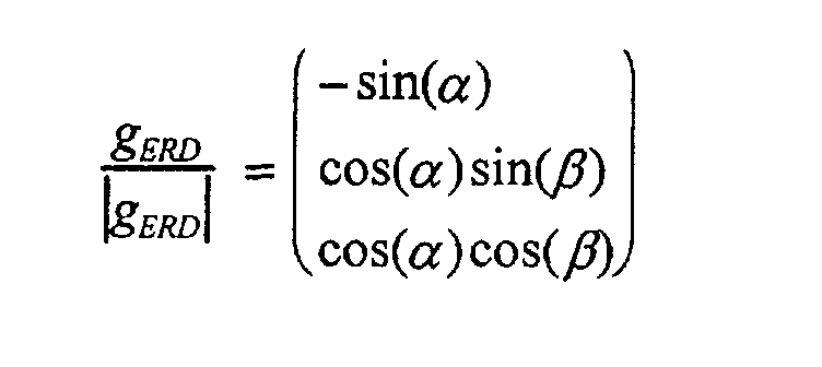
- Procédé de stabilisation de compas magnétiques, oùa) aux instants tj-1 et t1 avec j = 1,..., n, dans un système de coordonnées cartésiennes, avec les axes X, Y et Z, on mesure les composantes HX, HY et HZ du facteur de champ H du champ magnétique terrestre et des composantes gx et gy du vecteur, normé à 1, g = gGES/|gGES| de l'accélération globale gGES, qui se compose du vecteur de l'accélération terrestre gERD et du vecteur d'accélération véhicule/compas, a, le facteur d'accélération terrestre partant de l'origine du système de coordonnées en XYZ et, dans le cas où le compas magnétique est orienté horizontalement, coïncide avec l'axe Z, et l'axe X forme la ligne de visée, de sorte que les grandeurs gXj et gYj et HXj, HYj et HZj et les composantes de g sont exprimées à l'aide de l'angle de tangage α et de l'angle de roulis β sous la forme :
 b) les variations temporelles des composantes gX et gY du vecteur d'accélération globale sont déterminées,c) les variations temporelles des composantes HX, HY, Hz du vecteur magnétique H et de sa valeur absolue (H| sont déterminées,d) dans le système de coordonnées XYZ, on suppose une rotation autour de l'axe Y seul et, en prenant en considération les composantes de H aux moments j et j-1, précisément Hj et Hj-1 dans le plan X-Z, précisément HXj, HYj-1 et HZj-1, la vitesse de rotation ωYj Δt au cours de l'axe Y est déterminée :e) dans le système de coordonnées XYZ, on suppose une rotation autour de l'axe X seul et, en prenant en considération les composantes de H aux moments j et j-1, précisément Hj et Hj-1 dans le plan Y-Z, précisément HXj, HYj-1 et HZj-1, la vitesse de rotation ωXj Δt au cours de l'axe Y est déterminée :f) en ce que des fonctions de qualité pour la modification de l'horizon mesuré sont déterminées d'après la variation temporelle des composantes du vecteur d'accélération globale g, selon:g) en ce que des fonctions de qualité pour des variations autorisées de l'horizon mesuré sont déterminées en utilisant l'angle de rotation du vecteur de champ magnétique H, selonh) en ce que des facteurs de poids GXj pour gX et GYj pour gY sont déterminés en tant que fonctions des fonctions de qualité déterminées sous f) et g), selon :i) et en ce que les grandeurs stabilisées sont obtenues ensuite à l'aide des facteurs de pondération, d'après la relation
 - Procédé selon la revendication 1, caractérisé en ce que des composants normés du vecteur d'accélération globale mesurée sont utilisés, satisfaisant à l'égalité gx 2 + gY 2 + GZ 2 = 1.
- Procédé selon la revendication 1, caractérisé en ce que le facteur f a une valeur comprise entre 3 et 8, de préférence entre 5 et 6.
Applications Claiming Priority (3)
| Application Number | Priority Date | Filing Date | Title |
|---|---|---|---|
| DE19532122A DE19532122C1 (de) | 1995-08-31 | 1995-08-31 | Verfahren zur Horizontstabilisierung von Magnetkompassen |
| DE19532122 | 1995-08-31 | ||
| PCT/EP1996/003681 WO1997008513A1 (fr) | 1995-08-31 | 1996-08-21 | Procede de stabilisation de l'horizon de compas magnetiques |
Publications (2)
| Publication Number | Publication Date |
|---|---|
| EP0847518A1 EP0847518A1 (fr) | 1998-06-17 |
| EP0847518B1 true EP0847518B1 (fr) | 2002-06-05 |
Family
ID=7770904
Family Applications (1)
| Application Number | Title | Priority Date | Filing Date |
|---|---|---|---|
| EP96930068A Expired - Lifetime EP0847518B1 (fr) | 1995-08-31 | 1996-08-21 | Procede de stabilisation de l'horizon de compas magnetiques |
Country Status (11)
| Country | Link |
|---|---|
| US (1) | US5995913A (fr) |
| EP (1) | EP0847518B1 (fr) |
| JP (1) | JP3666875B2 (fr) |
| KR (1) | KR100421745B1 (fr) |
| CN (1) | CN1080414C (fr) |
| AT (1) | ATE218699T1 (fr) |
| AU (1) | AU703462B2 (fr) |
| CA (1) | CA2227617C (fr) |
| DE (2) | DE19532122C1 (fr) |
| NO (1) | NO323293B1 (fr) |
| WO (1) | WO1997008513A1 (fr) |
Families Citing this family (4)
| Publication number | Priority date | Publication date | Assignee | Title |
|---|---|---|---|---|
| DE19704956C1 (de) * | 1997-02-10 | 1998-06-18 | Leica Ag | Anordnung und Verfahren zum Messen der Richtung des Erdmagnetfeldes |
| CN102375160B (zh) * | 2010-08-04 | 2014-08-27 | 美新半导体(无锡)有限公司 | 一种校准两轴地磁传感器软硬磁误差的方法 |
| TWI509271B (zh) * | 2013-12-09 | 2015-11-21 | Voltafield Technology Corp | 磁場感測器與使用該磁場感測器的電子羅盤 |
| CN115103295B (zh) * | 2022-05-18 | 2023-03-24 | 慧之安信息技术股份有限公司 | 基于uwb的场馆人员定位系统 |
Family Cites Families (6)
| Publication number | Priority date | Publication date | Assignee | Title |
|---|---|---|---|---|
| US3899834A (en) * | 1972-10-02 | 1975-08-19 | Westinghouse Electric Corp | Electronic compass system |
| DE3422490A1 (de) * | 1984-06-16 | 1985-12-19 | Robert Bosch Gmbh, 7000 Stuttgart | Verfahren zur korrektur von winkelfehlern bei einem elektronischen kompass in fahrzeugen |
| JPH0518750A (ja) * | 1991-07-09 | 1993-01-26 | Takao Yamaguchi | 全範囲傾斜方位測定装置 |
| JPH06221852A (ja) * | 1993-01-25 | 1994-08-12 | Sato Kogyo Co Ltd | 電子式ステレオクリノコンパス |
| DE4405180A1 (de) * | 1994-02-18 | 1995-08-24 | Mannesmann Kienzle Gmbh | Verfahren zur Rekonstruktion des Gierwinkels eines Fahrzeugs aus fehlerbehafteten Rohdaten |
| DE4439945C1 (de) * | 1994-11-09 | 1996-02-08 | Leica Ag | Verfahren zur Stabilisierung der Richtungsanzeige von Magnetkompassen |
-
1995
- 1995-08-31 DE DE19532122A patent/DE19532122C1/de not_active Expired - Fee Related
-
1996
- 1996-08-21 DE DE59609304T patent/DE59609304D1/de not_active Expired - Lifetime
- 1996-08-21 JP JP53129096A patent/JP3666875B2/ja not_active Expired - Lifetime
- 1996-08-21 US US08/981,408 patent/US5995913A/en not_active Expired - Lifetime
- 1996-08-21 AU AU69266/96A patent/AU703462B2/en not_active Expired
- 1996-08-21 CN CN96195217A patent/CN1080414C/zh not_active Expired - Lifetime
- 1996-08-21 WO PCT/EP1996/003681 patent/WO1997008513A1/fr active IP Right Grant
- 1996-08-21 AT AT96930068T patent/ATE218699T1/de active
- 1996-08-21 CA CA002227617A patent/CA2227617C/fr not_active Expired - Lifetime
- 1996-08-21 KR KR10-1998-0700616A patent/KR100421745B1/ko not_active IP Right Cessation
- 1996-08-21 EP EP96930068A patent/EP0847518B1/fr not_active Expired - Lifetime
-
1998
- 1998-02-25 NO NO19980790A patent/NO323293B1/no not_active IP Right Cessation
Also Published As
| Publication number | Publication date |
|---|---|
| AU6926696A (en) | 1997-03-19 |
| JP3666875B2 (ja) | 2005-06-29 |
| CN1189891A (zh) | 1998-08-05 |
| WO1997008513A1 (fr) | 1997-03-06 |
| CA2227617A1 (fr) | 1997-03-06 |
| AU703462B2 (en) | 1999-03-25 |
| KR19990035955A (ko) | 1999-05-25 |
| CN1080414C (zh) | 2002-03-06 |
| EP0847518A1 (fr) | 1998-06-17 |
| ATE218699T1 (de) | 2002-06-15 |
| NO980790L (no) | 1998-04-01 |
| CA2227617C (fr) | 2007-04-24 |
| DE19532122C1 (de) | 1997-02-20 |
| KR100421745B1 (ko) | 2004-06-23 |
| NO323293B1 (no) | 2007-03-05 |
| DE59609304D1 (de) | 2002-07-11 |
| US5995913A (en) | 1999-11-30 |
| NO980790D0 (no) | 1998-02-25 |
| JPH11510593A (ja) | 1999-09-14 |
Similar Documents
| Publication | Publication Date | Title |
|---|---|---|
| EP0852000B1 (fr) | Systeme de navigation pour un vehicule, notamment pour un vehicule routier | |
| DE102005033237B4 (de) | Verfahren zur Bestimmung und Korrektur von Fehlorientierungen und Offsets der Sensoren einer Inertial Measurement Unit in einem Landfahrzeug | |
| EP2422018A1 (fr) | Engin de chantier mobile équipé d'un dispositif de régulation de position d'un bras de travail et procédé pour réguler la position d'un bras de travail d'un engin de chantier mobile | |
| DE102010037942A1 (de) | GPS-basierende Nickerfassung für ein integriertes Stabilitätssteuersystem | |
| DE102008040212A1 (de) | Radaufhängung für ein Fahrzeug | |
| DE2254013A1 (de) | Anordnung zur pruefung eines in einem luftfahrzeug installierten traegheitsgeraets | |
| DE102015115282A1 (de) | Verfahren und Vorrichtung zum Feststellen einer Orientierung einer Sensoreinheit | |
| DE2741274C3 (de) | Gerät zur automatischen Bestimmung der Nordrichtung | |
| DE3229819C2 (de) | Integriertes Navigations- und Feuerleitsystem für Kampfpanzer | |
| DE102019132150A1 (de) | Verfahren zum automatischen Kalibrieren eines Umfeldsensors, insbesondere eines Lidar-Sensors, eines Fahrzeugs auf Grundlage von Belegungskarten sowie Recheneinrichtung | |
| DE3321922A1 (de) | Schwerpunkt-messeinrichtung fuer in der luft befindliche flugzeuge | |
| DE2922414C2 (de) | Kurs-Lage-Referenzgerät | |
| EP0847518B1 (fr) | Procede de stabilisation de l'horizon de compas magnetiques | |
| DE2922415C2 (de) | Navigationsgerät für Landfahrzeuge | |
| DE19837905B4 (de) | Vorrichtung zum Korrigieren der Fahrzeugrichtung | |
| DE19829582C1 (de) | Verfahren und Vorrichtung zur Drehratenbestimmung, insbesondere der Gier-Drehrate eines Kraftfahrzeugs | |
| DE60024835T2 (de) | Integriertes inertial/fahrzeugbewegungssensor navigationssystem | |
| CH635428A5 (de) | Vorrichtung zur bestimmung der lotrichtung in einem auf einer bewegbaren unterlage angebrachten system. | |
| DE3141342C2 (de) | Kurs-Lage-Referenzgerät mit zweiachsiger Plattform | |
| EP0468193A2 (fr) | Procédé pour déterminer le nord | |
| DE3214379C2 (de) | Vorrichtung zur magnetischen Lageregelung eines Satelliten | |
| EP0557592A1 (fr) | Dispositif pour calibrer un appareil de mesure | |
| EP3819596A1 (fr) | Système de vérification d'une unité de mesure inertielle | |
| DE2434916A1 (de) | Kompassystem | |
| DE2923988C2 (de) | Navigationseinrichtung für Oberflächenfahrzeuge |
Legal Events
| Date | Code | Title | Description |
|---|---|---|---|
| PUAI | Public reference made under article 153(3) epc to a published international application that has entered the european phase |
Free format text: ORIGINAL CODE: 0009012 |
|
| 17P | Request for examination filed |
Effective date: 19971013 |
|
| AK | Designated contracting states |
Kind code of ref document: A1 Designated state(s): AT CH DE FI FR GB IT LI NL SE |
|
| RAP1 | Party data changed (applicant data changed or rights of an application transferred) |
Owner name: LEICA GEOSYSTEMS AG |
|
| GRAG | Despatch of communication of intention to grant |
Free format text: ORIGINAL CODE: EPIDOS AGRA |
|
| GRAG | Despatch of communication of intention to grant |
Free format text: ORIGINAL CODE: EPIDOS AGRA |
|
| GRAH | Despatch of communication of intention to grant a patent |
Free format text: ORIGINAL CODE: EPIDOS IGRA |
|
| 17Q | First examination report despatched |
Effective date: 20011031 |
|
| GRAH | Despatch of communication of intention to grant a patent |
Free format text: ORIGINAL CODE: EPIDOS IGRA |
|
| GRAA | (expected) grant |
Free format text: ORIGINAL CODE: 0009210 |
|
| AK | Designated contracting states |
Kind code of ref document: B1 Designated state(s): AT CH DE FI FR GB IT LI NL SE |
|
| REF | Corresponds to: |
Ref document number: 218699 Country of ref document: AT Date of ref document: 20020615 Kind code of ref document: T |
|
| REG | Reference to a national code |
Ref country code: GB Ref legal event code: FG4D Free format text: NOT ENGLISH |
|
| REG | Reference to a national code |
Ref country code: CH Ref legal event code: EP |
|
| REF | Corresponds to: |
Ref document number: 59609304 Country of ref document: DE Date of ref document: 20020711 |
|
| REG | Reference to a national code |
Ref country code: CH Ref legal event code: NV Representative=s name: BUECHEL, KAMINSKI & PARTNER PATENTANWAELTE ESTABLI |
|
| GBT | Gb: translation of ep patent filed (gb section 77(6)(a)/1977) |
Effective date: 20020815 |
|
| ET | Fr: translation filed | ||
| PLBE | No opposition filed within time limit |
Free format text: ORIGINAL CODE: 0009261 |
|
| STAA | Information on the status of an ep patent application or granted ep patent |
Free format text: STATUS: NO OPPOSITION FILED WITHIN TIME LIMIT |
|
| 26N | No opposition filed |
Effective date: 20030306 |
|
| REG | Reference to a national code |
Ref country code: CH Ref legal event code: PFA Owner name: LEICA GEOSYSTEMS AG Free format text: LEICA GEOSYSTEMS AG# #9435 HEERBRUGG (CH) -TRANSFER TO- LEICA GEOSYSTEMS AG# #9435 HEERBRUGG (CH) |
|
| REG | Reference to a national code |
Ref country code: FR Ref legal event code: PLFP Year of fee payment: 20 |
|
| PGFP | Annual fee paid to national office [announced via postgrant information from national office to epo] |
Ref country code: CH Payment date: 20150819 Year of fee payment: 20 Ref country code: DE Payment date: 20150821 Year of fee payment: 20 Ref country code: GB Payment date: 20150819 Year of fee payment: 20 Ref country code: FI Payment date: 20150812 Year of fee payment: 20 |
|
| PGFP | Annual fee paid to national office [announced via postgrant information from national office to epo] |
Ref country code: AT Payment date: 20150820 Year of fee payment: 20 Ref country code: FR Payment date: 20150820 Year of fee payment: 20 Ref country code: SE Payment date: 20150819 Year of fee payment: 20 Ref country code: NL Payment date: 20150830 Year of fee payment: 20 |
|
| PGFP | Annual fee paid to national office [announced via postgrant information from national office to epo] |
Ref country code: IT Payment date: 20150824 Year of fee payment: 20 |
|
| REG | Reference to a national code |
Ref country code: DE Ref legal event code: R071 Ref document number: 59609304 Country of ref document: DE |
|
| REG | Reference to a national code |
Ref country code: NL Ref legal event code: MK Effective date: 20160820 |
|
| REG | Reference to a national code |
Ref country code: CH Ref legal event code: PL |
|
| REG | Reference to a national code |
Ref country code: GB Ref legal event code: PE20 Expiry date: 20160820 |
|
| REG | Reference to a national code |
Ref country code: SE Ref legal event code: EUG |
|
| REG | Reference to a national code |
Ref country code: AT Ref legal event code: MK07 Ref document number: 218699 Country of ref document: AT Kind code of ref document: T Effective date: 20160821 |
|
| PG25 | Lapsed in a contracting state [announced via postgrant information from national office to epo] |
Ref country code: GB Free format text: LAPSE BECAUSE OF EXPIRATION OF PROTECTION Effective date: 20160820 |