EP0846528B1 - Fluidbetriebenes Schlagwerk mit einer Schutzvorrichtung - Google Patents
Fluidbetriebenes Schlagwerk mit einer Schutzvorrichtung Download PDFInfo
- Publication number
- EP0846528B1 EP0846528B1 EP97111722A EP97111722A EP0846528B1 EP 0846528 B1 EP0846528 B1 EP 0846528B1 EP 97111722 A EP97111722 A EP 97111722A EP 97111722 A EP97111722 A EP 97111722A EP 0846528 B1 EP0846528 B1 EP 0846528B1
- Authority
- EP
- European Patent Office
- Prior art keywords
- impact device
- tool
- transverse
- percussive tool
- housing part
- Prior art date
- Legal status (The legal status is an assumption and is not a legal conclusion. Google has not performed a legal analysis and makes no representation as to the accuracy of the status listed.)
- Expired - Lifetime
Links
- 238000007789 sealing Methods 0.000 claims description 19
- 239000013013 elastic material Substances 0.000 claims description 4
- 238000006073 displacement reaction Methods 0.000 claims 2
- 238000012216 screening Methods 0.000 claims 1
- 238000009527 percussion Methods 0.000 abstract description 6
- 230000007246 mechanism Effects 0.000 description 18
- 239000000463 material Substances 0.000 description 8
- 230000001681 protective effect Effects 0.000 description 4
- 238000010276 construction Methods 0.000 description 2
- 239000000356 contaminant Substances 0.000 description 2
- 230000006378 damage Effects 0.000 description 2
- 239000000428 dust Substances 0.000 description 2
- 239000012535 impurity Substances 0.000 description 2
- 238000009413 insulation Methods 0.000 description 2
- 239000011435 rock Substances 0.000 description 2
- 230000000694 effects Effects 0.000 description 1
- 239000012530 fluid Substances 0.000 description 1
- 238000012423 maintenance Methods 0.000 description 1
- 239000002184 metal Substances 0.000 description 1
- 230000035515 penetration Effects 0.000 description 1
- 230000002028 premature Effects 0.000 description 1
- 239000010453 quartz Substances 0.000 description 1
- VYPSYNLAJGMNEJ-UHFFFAOYSA-N silicon dioxide Inorganic materials O=[Si]=O VYPSYNLAJGMNEJ-UHFFFAOYSA-N 0.000 description 1
Images

Classifications
-
- B—PERFORMING OPERATIONS; TRANSPORTING
- B25—HAND TOOLS; PORTABLE POWER-DRIVEN TOOLS; MANIPULATORS
- B25D—PERCUSSIVE TOOLS
- B25D17/00—Details of, or accessories for, portable power-driven percussive tools
-
- Y—GENERAL TAGGING OF NEW TECHNOLOGICAL DEVELOPMENTS; GENERAL TAGGING OF CROSS-SECTIONAL TECHNOLOGIES SPANNING OVER SEVERAL SECTIONS OF THE IPC; TECHNICAL SUBJECTS COVERED BY FORMER USPC CROSS-REFERENCE ART COLLECTIONS [XRACs] AND DIGESTS
- Y10—TECHNICAL SUBJECTS COVERED BY FORMER USPC
- Y10T—TECHNICAL SUBJECTS COVERED BY FORMER US CLASSIFICATION
- Y10T279/00—Chucks or sockets
- Y10T279/17—Socket type
- Y10T279/17042—Lost motion
- Y10T279/17094—Sleeve type retainer
- Y10T279/17102—Sleeve in socket
Definitions
- the invention relates to a fluid-powered hammer mechanism with a protective device and a housing part connected to the striking mechanism, which at least the striking mechanism shields against the outside environment and in which one of the Percussion driven impact tool protrudes.
- the housing part instructs its passage opening for the striking tool on an outer seal the striking tool transverse to its longitudinal axis at most with a small distance encloses and is designed to be movable in this transverse direction.
- Impact mechanisms driven by a fluid pressure medium are mainly used for material destruction. It falls in addition to the material broken into coarse pieces, also rock dust Grain fractions up to the size of a few millimeters. Because this rock dust in most cases a high proportion of wear-promoting materials (e.g. quartz) has its penetration into the tool guide increased wear and possibly premature failure of the affected Components result.
- wear-promoting materials e.g. quartz
- the invention has for its object a fluid-powered To create striking mechanism with a protective device, especially in rough construction site use expected stresses.
- a fluid-powered To create striking mechanism with a protective device especially in rough construction site use expected stresses.
- functional reliability due to reduced wear in the area of the tool guide of the striking mechanism increased as well as the repair and maintenance effort be reduced.
- the basic idea of the invention is then the striking mechanism Seen in the opposite direction to the striking direction of the striking tool - in the area in front of the tool guide with an external seal in the form of a movable mounted cross slide, against the direction of impact an elastically supporting inner seal connected downstream of the impact tool is.
- the cross slide also acts as a mechanical shield is and serves as a scraper, the inner seal downstream of this Prevent fine impurities from entering the tool guide area.
- the percussion mechanism itself can be of any design as far as it is in a tool guide back and forth movable impact tool, which is driven by the striking mechanism.
- the protective device in question is characterized in that that the outer seal as a transverse slide mounted in a transverse guide is formed as a unit for transverse movements of the striking tool by this is moved; that the outer seal against the direction of impact of the Impact tool an inner seal is connected to the impact tool rests elastically outside of its tool guide, and that the External and internal seals can be replaced (on the component that carries them) are attached.
- the cross slide can - according to the requirements placed on it - consist of different materials, in particular metal or plastic.
- Essential in the context mentioned here is such a configuration of the cross slide, which ensures that it is sufficiently movable as a unit in the transverse direction, ie is displaced by any transverse movements of the striking tool with respect to the transverse guide receiving it.
- the cross slide is disc-shaped (claim 2); he should be like this be designed so that it is sufficient in the longitudinal direction of the striking tool Has rigidity.
- the cross slide can be advantageously designed in that it has a passage opening has, the wall facing the striking tool convex is arched (claim 3).
- cross slide should be designed in such a way that it is in rigid unit forms (claim 4).
- the cross slide can be operated simultaneously also consist of several materials; in particular, it can be configured in this way be that the wall of the passage opening for the striking tool of otherwise rigid cross slide at least partially made of elastic Material consists (claim 5); rubber-like materials in particular come as materials Materials or plastic.
- the cross slide preferably faces the one facing the striking tool Side on an elastic insert, which the wall of the passage opening at least forms (claim 6).
- the elastic insert can advantageously also be dimensioned and designed such that that it rests on the striking tool and thus an additional seal forms.
- the cross slide forms a replacement component with the transverse guide supporting it, which is releasably attached to the housing part (claim 8).
- the inner seal is preferably designed such that it has at least one on the striking tool sealing lip (claim 9).
- At least one sealing lip of the inner seal should face in the direction of impact be arranged obliquely (claim 10).
- the inner seal can be attached to any components of the overall device.
- a particularly simple embodiment is characterized in that the inner seal is attached to an extension of the tool guide, the extension in the area of the inner seal enclosing the striking tool at a distance which is greater than the greatest possible transverse offset of the striking tool (claim 12).
- the housing part already mentioned, which at least the cross slide can be part of the percussion mechanism itself.
- the subject of the invention can also be used in configurations come in which the housing part is part of a supporting the striking mechanism Outer housing is (claim 13).
- the housing part forms the front end of the outer housing.
- the inner seal with respect to the tool guide is preferably arranged such that the distance of the sealing lip from the front edge of the tool guide (ie from the end section of the tool guide facing the outer seal) is greater than the maximum stroke of the striking tool (claim 14). In this way it is ensured that the contact area of the sealing lip does not coincide with the guide area of the impact tool. In the area of the front edge of the tool guide, the striking tool is subject to a particularly high load, which can result in damage to the outer surface of the striking tool.
- the design of the inner seal in question prevents the sealing lip of the inner seal from coming into contact with the possibly attacked outer surface of the striking tool and thereby possibly being damaged prematurely or failing prematurely.
- the inner seal should be regarding the outer seal should be arranged so that after removing the Cross slide or the replacement component comprising this (cf. claim 8) is accessible from the outside and can be dismantled if necessary.
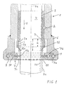
- FIG. 1 shows whose lower part 1, in which a tool guide 3 is immovable via a bolt 2 is held.
- a striking tool in the form of a chisel is supported in this 4 with the longitudinal axis 4a movable in the longitudinal direction.
- the movement of the chisel 4 in the direction of impact is indicated by an arrow 5.
- the pendulum movements possibly carried out by the chisel 4 are greatly enlarged - schematically illustrated by dashed lines 4b and 4c.
- a housing part 6 is fastened to the striking tool lower part 1 as an extension, which at the end (i.e. in the illustration below) is a removable component 7 receives.
- the housing part 6 is equipped with a recess 8, which is dimensioned slightly lower than the height of the replacement component 7 and their diameter adapted to the diameter of the exchange component 7 is.
- the parts 6 and 7 are detachably fastened to one another via bolts 9.
- the exchange component 7 in turn consists of an end plate 7a and a back plate 7b. These are designed so that on the one hand they are sufficiently large Passage opening 7c for the chisel 4 and on the other hand - transverse to the longitudinal axis 4a - define an annulus 10; in this is an outer seal in the form of a plate-shaped cross slide 11 movably mounted.
- the height of the annular space 10 in the direction of the longitudinal axis 4a is slightly larger dimensioned as the thickness of the cross slide 11, so that this under the influence of Chisel 4 executing transverse movements with respect to the housing part 6 as in itself rigid unit can be moved back and forth.
- the parts 7a and 7b are connected to each other (not shown); accordingly can the exchange component 7 with the freely movably mounted therein Cross slide 11 can be installed and removed as a unit.
- the cross slide 11 is - against the direction of impact (arrow 5) within the housing part 6 an inner seal 12 connected downstream, the sealing lip 12a outside the tool guide 3 rests elastically on the chisel 4 and as the main scraper for impurities which may have penetrated into the housing part 6.
- the inner seal 12 is on an extension 3a of the tool guide releasably attached via a fastening groove 3b; the Extension encloses the chisel 4 in the area of the inner seal a distance s that is greater than the greatest possible transverse offset of the chisel in this area (indicated by lines 4b and 4c).
- the length of the sealing lip 12a is such that the ratio of their length and the greatest possible transverse offset of the chisel 4 has a value greater than 2 in the area of the sealing lip 12a.
- the stripping zone of the inner seal 12 is arranged such that the distance K of Sealing lip 12a from the front edge 3c of the bit guide 3 is larger than the maximum Stroke H of the chisel 4. This ensures that the contact area the sealing lip 12a does not coincide with the guide area of the chisel 4.
- the inner seal takes on 12 with respect to the replacement component 7, a position which, after removal of the Part 7, the inner seal 12 accessible from the front of the component 6 from the outside makes.
- the component 6 receiving the exchange component 7 is part of a Outer housing 13, which surrounds the striking mechanism - supporting it.
- the latter can be displaced in the direction of impact (arrow 5) so far in the direction of the replacement component 7 that its sealing lip 12a is only a short distance from the longitudinal slide 4a in the direction of the longitudinal axis 4a.
- This arrangement has the consequence, among other things, that the area of the inner seal 12 (after removal of part 7 and chisel 4) is particularly easy to see and access.
- FIG. 1 is the annular space (shown in FIG. 1) 10 - which is limited by parts 7a, 7b and 11 - with a ring 14 filled in elastic material.
- the cross slide 11 shows the endeavor with respect to the longitudinal axis 4a of the chisel 4 to assume a predetermined central position.
- the resilient support within the replacement component 7 has the result that undesirable rattling movements - and thus the resulting noise development - be dampened.
- the wall 11a can also have a sealing ring made of elastic material be equipped, which is constantly on the outer surface of the chisel 4 and thus - in addition to the inner seal 12 - forms a further sealing point.
Landscapes
- Engineering & Computer Science (AREA)
- Mechanical Engineering (AREA)
- Percussive Tools And Related Accessories (AREA)
Description
Dies setzt voraus, daß der Querschieber im Bereich seiner Durchtrittsöffnung eine Ausgestaltung aufweist, welche ein Verkanten des Querschiebers auch bei relativ dazu schräg gestelltem Schlagwerkzeug ausschließt.
Eine besonders einfache Ausführungsform ist dadurch gekennzeichnet, daß die Innendichtung an einer Verlängerung der Werkzeugführung befestigt ist, wobei die Verlängerung im Bereich der Innendichtung das Schlagwerkzeug mit einem Abstand umschließt, der größer ist als der größtmögliche Querversatz des Schlagwerkzeugs (Anspruch 12).
Im Bereich der Vorderkante der Werkzeugführung unterliegt das Schlagwerkzeug einer besonders hohen Beanspruchung, die Beschädigungen an der Außenfläche des Schlagwerkzeugs zur Folge haben kann. Durch die in Rede stehende Ausgestaltung der Innendichtung wird verhindert, daß die Dichtlippe der Innendichtung mit der etwa angegriffenen Außenfläche des Schlagwerkzeugs in Berührung kommt und dadurch möglicherweise vorzeitig beschädigt wird bzw. vorzeitig ausfällt.
- Fig.1
- schematisiert einen Teilschnitt durch das Unterteil eines Schlagwerks mit einem zugehörigen Gehäuseteil, welcher ein Austausch-Bauteil mit einer verschiebbar gelagerten Außendichtung aufnimmt, und
- Fig.2
- schematisiert einen Teilschnitt durch das Unterteil eines Schlagwerks mit einem dieses umschließenden Außengehäuse und einem eine Außendichtung aufnehmenden Gehäuseteil, welcher seinerseits Bestandteil des Außengehäuses ist.
Diese Anordnung hat unter anderem zur Folge, daß der Bereich der Innendichtung 12 (nach Ausbau des Teils 7 und des Meißels 4) besonders gut einzusehen und zugänglich ist.
Claims (14)
- Fluidbetriebenes Schlagwerk mit einer Schutzvorrichtung und einem mit dem Schlagwerk verbundenen Gehäuseteil (6), der das Schlagwerk zumindest stirnseitig gegen die Außenumgebung abschirmt und in welchen ein vom Schlagwerk angetriebenes Schlagwerkzeug (4) hineinragt, wobei das Gehäuseteil (6) an seiner Durchtrittsöffnung für das Schlagwerkzeug (4) eine Außendichtung (11) aufweist, die das Schlagwerkzeug (4) quer zu seiner Längsachse (4a) allenfalls mit geringem Abstand umschließt und in dieser Querrichtung beweglich ausgebildetist, dadurch gekennzeichnet, daß die Außendichtung (11) als in einer Querführung (7a, 7b) gelagerter Querschieber ausgebildet ist, der als Einheit bei Querbewegungen des Schlagwerkzeugs (4) von diesem mitbewegt wird;
daß der Außendichtung (11) entgegen der Schlagrichtung (Pfeil 5) des Schlagwerkzeugs (4) eine Innendichtung (12) nachgeschaltet ist, die an dem Schlagwerkzeug (4) außerhalb von dessen Werkzeugführung (3) elastisch anliegt,
und daß die Außen- und die Innendichtung (11 bzw. 12) jeweils auswechselbar befestigt sind. - Schlagwerk nach Anspruch 1, dadurch gekennzeichnet, daß der Querschieber (11) scheibenförmig ausgebildet ist.
- Schlagwerk nach zumindest einem der vorhergehenden Ansprüche,
dadurch gekennzeichnet, daß der Querschieber (11) eine Durchtrittsöffnung aufweist, deren dem Schlagwerkzeug (4) zugewandte Wandung (11a) konvex gewölbt ist. - Schlagwerk nach zumindest einem der vorhergehenden Ansprüche,
dadurch gekennzeichnet, daß der Querschieber (11) als in sich starre Einheit ausgebildet ist. - Schlagwerk nach zumindest einem der Ansprüche 1 bis 3,
dadurch gekennzeichnet, daß die Wandung (11a) der Durchtrittsöffnung des im übrigen in sich starren Querschiebers (11) für das Schlagwerkzeug (4) zumindest teilweise aus elastischem Werkstoff besteht. - Schlagwerk nach Anspruch 5, dadurch gekennzeichnet, daß der Querschieber (11) auf der dem Schlagwerkzeug (4) zugewandten Seite einen elastischen Einsatz aufweist, welcher die Wandung (11a) der Durchtrittsöffnung zumindest mitbildet.
- Schlagwerk nach zumindest einem der vorhergehenden Ansprüche,
dadurch gekennzeichnet, daß der Querschieber (11) quer zur Schlagrichtung (Pfeil 5) elastisch abgestützt ist. - Schlagwerk nach zumindest einem der vorhergehenden Ansprüche,
dadurch gekennzeichnet, daß der Querschieber (11) mit der ihn abstützenden Querführung (7a, 7b) ein Austausch-Bauteil (7) bildet, das lösbar an dem Gehäuseteil (6) befestigt ist. - Schlagwerk nach zumindest einem der vorhergehenden Ansprüche,
dadurch gekennzeichnet, daß die Innendichtung (12) zumindest eine am Schlagwerkzeug (4) anliegende Dichtlippe (12a) aufweist. - Schlagwerk nach Anspruch 9, dadurch gekennzeichnet, daß zumindest eine Dichtlippe (12a) der Innendichtung (12) in Schlagrichtung (Pfeil 5) schräg verlaufend angeordnet ist.
- Schlagwerk nach zumindest einem der Ansprüche 9 und 10,
dadurch gekennzeichnet, daß das Verhältnis aus der Länge jeder Dichtlippe (12a) und dem größtmöglichen Querversatz des Schlagwerkzeugs (4) zumindest 1 bis 3 beträgt. - Schlagwerk nach zumindest einem der vorhergehenden Ansprüche,
dadurch gekennzeichnet, daß die Innendichtung (12) an einer Verlängerung (3a) der Werkzeugführung (3) befestigt ist und die Verlängerung (3a) im Bereich der Innendichtung (12) das Schlagwerkzeug (4) mit einem Abstand (s) umschließt, der größer ist als der größtmögliche Querversatz des Schlagwerkzeugs (4). - Schlagwerk nach zumindest einem der vorhergehenden Ansprüche,
dadurch gekennzeichnet, daß das Gehäuseteil (6) Bestandteil eines Außengehäuses (13) ist, in dem das Schlagwerk abgestützt ist. - Schlagwerk nach zumindest einem der Ansprüche 9 bis 13,
dadurch gekennzeichnet, daß der Abstand (K) der Dichtlippe (12a) von der Vorderkante (3c) der Werkzeugführung (3) größer ist als der maximale Hub (H) des Schlagwerkzeugs (4).
Applications Claiming Priority (2)
| Application Number | Priority Date | Filing Date | Title |
|---|---|---|---|
| DE19628815A DE19628815C2 (de) | 1996-07-17 | 1996-07-17 | Schutzvorrichtung zum Verhindern des Eindringens von Verunreinigungen an einem fluidbetriebenen Schlagwerk |
| DE19628815 | 1996-07-17 |
Publications (2)
| Publication Number | Publication Date |
|---|---|
| EP0846528A1 EP0846528A1 (de) | 1998-06-10 |
| EP0846528B1 true EP0846528B1 (de) | 2002-04-03 |
Family
ID=7800073
Family Applications (1)
| Application Number | Title | Priority Date | Filing Date |
|---|---|---|---|
| EP97111722A Expired - Lifetime EP0846528B1 (de) | 1996-07-17 | 1997-07-10 | Fluidbetriebenes Schlagwerk mit einer Schutzvorrichtung |
Country Status (6)
| Country | Link |
|---|---|
| US (1) | US5873579A (de) |
| EP (1) | EP0846528B1 (de) |
| JP (1) | JP4037938B2 (de) |
| AT (1) | ATE215427T1 (de) |
| DE (1) | DE19628815C2 (de) |
| ES (1) | ES2171786T3 (de) |
Families Citing this family (14)
| Publication number | Priority date | Publication date | Assignee | Title |
|---|---|---|---|---|
| DE19851444B4 (de) * | 1998-11-09 | 2008-05-15 | Atlas Copco Construction Tools Gmbh | Ausbauvorrichtung für die äußere, als Werkzeugabstützung dienende Führungsbuchse im Gehäuse eines Schlagwerks |
| DE10012916A1 (de) | 2000-03-16 | 2001-09-20 | Krupp Berco Bautechnik Gmbh | Schutzvorrichtung zum Verhindern des Eindringens von Verunreinigungen an einem fluidbetriebenen Schlagwerk |
| US6510904B1 (en) * | 2000-05-26 | 2003-01-28 | Nippon Pneumatic Mfg. Co., Ltd. | Protected tool bushing for an impact hammer |
| DE10061810A1 (de) * | 2000-12-12 | 2002-06-13 | Hilti Ag | Schlagendes Handwerkzeuggerät mit drehendem Führungsrohr |
| US6761723B2 (en) * | 2002-01-14 | 2004-07-13 | Dynamic Spine, Inc. | Apparatus and method for performing spinal surgery |
| DE10202648A1 (de) * | 2002-01-23 | 2003-07-31 | Atlas Copco Constr Tools Ab | Halterung für die Innendichtung an einem fluidbetriebenen Schlagwerk |
| DE10257483A1 (de) * | 2002-12-10 | 2004-07-01 | Hilti Ag | Werkzeugaufnahme für flüssigkeitsgespülte Schlagwerkzeuge |
| WO2005013852A2 (en) * | 2003-08-07 | 2005-02-17 | Dynamic Spine, Inc. | Intervertebral prosthetic device and associated devices and methods for implanting the intervertebral prosthetic device |
| SE528035C2 (sv) * | 2004-03-12 | 2006-08-15 | Atlas Copco Constr Tools Ab | Hydraulisk brythammare med smord verktygshylsa |
| US8360167B2 (en) * | 2010-08-11 | 2013-01-29 | Caterpillar Inc. | Composite seal for a hydraulic hammer |
| US9102045B2 (en) * | 2011-09-29 | 2015-08-11 | Caterpillar Inc. | System and method for easy removal of hydraulic hammer bushing |
| KR101592447B1 (ko) * | 2014-06-11 | 2016-02-11 | 대모 엔지니어링 주식회사 | 하부밀폐 부재를 구비한 유압브레이커 |
| US10065301B2 (en) * | 2015-02-05 | 2018-09-04 | Caterpillar Inc. | Lower buffer and bushing protector |
| EP3446835B1 (de) * | 2017-08-21 | 2025-06-04 | Sandvik Mining and Construction Oy | Abbruchhammer und verfahren zum dichten ein werkzeug eines abbruchhammers |
Family Cites Families (11)
| Publication number | Priority date | Publication date | Assignee | Title |
|---|---|---|---|---|
| US2764138A (en) * | 1953-03-02 | 1956-09-25 | Atlas Copco Ab | Percussion tools having a reciprocable hammer piston actuated by combustion gases |
| DE1678280A1 (de) * | 1967-10-18 | 1972-05-18 | Mutzhas Maximilian F | Sicherheits-Skibindung |
| DE3125454A1 (de) * | 1981-06-29 | 1983-01-20 | Hilti AG, 9494 Schaan | Bohrhammer fuer bohr- und schlagbohrbetrieb |
| DE3440530A1 (de) * | 1983-11-02 | 1985-05-09 | Heinrich 1000 Berlin Henze | Hydraulischer aufbruchhammer |
| US4694911A (en) * | 1984-07-13 | 1987-09-22 | Kennedy James D | Drilling assembly for percussion drilling of deep wells |
| DE8436752U1 (de) * | 1984-12-15 | 1985-03-21 | Röhm, Günter Horst, 7927 Sontheim | Bohrfutter |
| DE3606331A1 (de) * | 1986-02-27 | 1987-09-03 | Bosch Gmbh Robert | Staubabdichtung |
| DE9115805U1 (de) * | 1991-12-20 | 1993-04-15 | Robert Bosch Gmbh, 7000 Stuttgart | Staubkappe für Bohrgeräte |
| SE9201340L (sv) * | 1992-04-29 | 1993-10-30 | Berema Atlas Copco Ab | Slående maskin |
| US5301761A (en) * | 1993-03-09 | 1994-04-12 | Ingersoll-Rand Company | Pressure reversing valve for a fluid-actuated, percussive drilling apparatus |
| US5562170A (en) * | 1995-08-30 | 1996-10-08 | Ingersoll-Rand Company | Self-lubricating, fluid-actuated, percussive down-the-hole drill |
-
1996
- 1996-07-17 DE DE19628815A patent/DE19628815C2/de not_active Expired - Lifetime
-
1997
- 1997-07-10 ES ES97111722T patent/ES2171786T3/es not_active Expired - Lifetime
- 1997-07-10 EP EP97111722A patent/EP0846528B1/de not_active Expired - Lifetime
- 1997-07-10 AT AT97111722T patent/ATE215427T1/de active
- 1997-07-15 JP JP18941097A patent/JP4037938B2/ja not_active Expired - Lifetime
- 1997-07-16 US US08/895,237 patent/US5873579A/en not_active Expired - Lifetime
Also Published As
| Publication number | Publication date |
|---|---|
| DE19628815A1 (de) | 1998-01-22 |
| JPH1058353A (ja) | 1998-03-03 |
| US5873579A (en) | 1999-02-23 |
| EP0846528A1 (de) | 1998-06-10 |
| ATE215427T1 (de) | 2002-04-15 |
| JP4037938B2 (ja) | 2008-01-23 |
| DE19628815C2 (de) | 1999-02-25 |
| ES2171786T3 (es) | 2002-09-16 |
Similar Documents
| Publication | Publication Date | Title |
|---|---|---|
| EP0846528B1 (de) | Fluidbetriebenes Schlagwerk mit einer Schutzvorrichtung | |
| DE69327169T2 (de) | Bohrfutter | |
| EP0472982B1 (de) | Hydraulisch betriebene Schlagdrehbohrvorrichtung, insbesondere zum Ankerlochbohren | |
| DE29811073U1 (de) | Vorrichtung zum Sieben und/oder Zerkleinern von Siebmaterialien | |
| DE2717336A1 (de) | Pneumatischer hammerantrieb | |
| DE2111234B2 (de) | Schlagmeißel- oder Schlagbohrmaschine | |
| DE3515244A1 (de) | Schlagwerkzeug | |
| DE69837186T2 (de) | Anordnung in Verbindung mit einer hydraulischen Brechvorrichtung | |
| DE2844110A1 (de) | Handwerkzeugmaschine, insbesondere meisselhammer | |
| DE2810606C2 (de) | Meißel für ein im Gestein schlagend arbeitendes Brechwerkzeug | |
| EP1691954B1 (de) | Aufbruch- und/oder bohrhammer mit linear geführter griffeinrichtung | |
| DE69518161T2 (de) | Hydraulischer brechhammer | |
| DE69031836T2 (de) | Abrisshammer | |
| EP1136190B1 (de) | Schutzvorrichtung zum Verhindern des Eindringens von Verunreinigung an einem fluidbetriebenen Schlagwerk | |
| DE3842891A1 (de) | Rotationsbohrverfahren und rotationsbohreinrichtung zur durchfuehrung des verfahrens | |
| EP1342539B1 (de) | Halterung für die Innendichtung an einem fluidbetriebenen Schlagwerk | |
| DE4136584B4 (de) | Bohr- und Meisselgerät mit Werkzeugaufnahme | |
| DE3630444A1 (de) | Abtragvorrichtung fuer schneidenden materialabtrag | |
| DE102004039865B4 (de) | Bohrgerät | |
| EP3693532B1 (de) | Vorrichtung zum bohren in erdreich, verfahren zum herstellen einer vorrichtung zum bohren in erdreich, verfahren zum warten einer vorrichtung zum bohren in erdreich und verwendung einer vorrichtung zum bohren in erdreich | |
| DE9411545U1 (de) | Vorrichtung zur Halterung eines Schrämmeißels | |
| DE3241483C2 (de) | Schlaggerät | |
| DE102007005182B3 (de) | Verfahren zur Befestigung eines einsatzgehärteten Antriebszapfens am gehärteten Schermesser einer Heckenschere | |
| DE2838103A1 (de) | Verbesserter aushub(foerder)-bohrer | |
| DE4110261A1 (de) | Schalldaemmeinrichtung an einem handgefuehrten, fluidbetriebenen schlag- oder bohrwerkzeug |
Legal Events
| Date | Code | Title | Description |
|---|---|---|---|
| PUAI | Public reference made under article 153(3) epc to a published international application that has entered the european phase |
Free format text: ORIGINAL CODE: 0009012 |
|
| AK | Designated contracting states |
Kind code of ref document: A1 Designated state(s): AT CH ES FI FR GB IT LI SE |
|
| RAP1 | Party data changed (applicant data changed or rights of an application transferred) |
Owner name: KRUPP BERCO BAUTECHNIK GMBH |
|
| 17P | Request for examination filed |
Effective date: 19981210 |
|
| AKX | Designation fees paid |
Free format text: AT CH DE ES FI FR GB IT LI SE |
|
| RBV | Designated contracting states (corrected) |
Designated state(s): AT CH DE ES FI FR GB IT LI SE |
|
| GRAG | Despatch of communication of intention to grant |
Free format text: ORIGINAL CODE: EPIDOS AGRA |
|
| RTI1 | Title (correction) |
Free format text: PERCUSSIVE TOOL WITH FLUID-PRESSURE DRIVE AND A PROTECTION DEVICE |
|
| 17Q | First examination report despatched |
Effective date: 20010601 |
|
| GRAG | Despatch of communication of intention to grant |
Free format text: ORIGINAL CODE: EPIDOS AGRA |
|
| GRAH | Despatch of communication of intention to grant a patent |
Free format text: ORIGINAL CODE: EPIDOS IGRA |
|
| RBV | Designated contracting states (corrected) |
Designated state(s): AT CH ES FI FR GB IT LI SE |
|
| RIN1 | Information on inventor provided before grant (corrected) |
Inventor name: SCHAREINA, MARTIN Inventor name: DEIMEL, THOMAS Inventor name: PROKOP, HEINZ-JUERGEN, DR.-ING. Inventor name: FRITZ, KARLHEINZ Inventor name: AHR, THORSTEN |
|
| REG | Reference to a national code |
Ref country code: GB Ref legal event code: IF02 |
|
| REG | Reference to a national code |
Ref country code: DE Ref legal event code: 8566 |
|
| GRAH | Despatch of communication of intention to grant a patent |
Free format text: ORIGINAL CODE: EPIDOS IGRA |
|
| GRAA | (expected) grant |
Free format text: ORIGINAL CODE: 0009210 |
|
| AK | Designated contracting states |
Kind code of ref document: B1 Designated state(s): AT CH ES FI FR GB IT LI SE |
|
| REF | Corresponds to: |
Ref document number: 215427 Country of ref document: AT Date of ref document: 20020415 Kind code of ref document: T |
|
| REG | Reference to a national code |
Ref country code: CH Ref legal event code: EP |
|
| GBT | Gb: translation of ep patent filed (gb section 77(6)(a)/1977) |
Effective date: 20020403 |
|
| REG | Reference to a national code |
Ref country code: CH Ref legal event code: NV Representative=s name: TROESCH SCHEIDEGGER WERNER AG |
|
| ET | Fr: translation filed | ||
| REG | Reference to a national code |
Ref country code: ES Ref legal event code: FG2A Ref document number: 2171786 Country of ref document: ES Kind code of ref document: T3 |
|
| RAP2 | Party data changed (patent owner data changed or rights of a patent transferred) |
Owner name: ATLAS COPCO CONSTRUCTION TOOLS GMBH |
|
| REG | Reference to a national code |
Ref country code: CH Ref legal event code: PFA Free format text: KRUPP BERCO BAUTECHNIK GMBH TRANSFER- ATLAS COPCO CONSTRUCTION TOOLS GMBH |
|
| PLBE | No opposition filed within time limit |
Free format text: ORIGINAL CODE: 0009261 |
|
| STAA | Information on the status of an ep patent application or granted ep patent |
Free format text: STATUS: NO OPPOSITION FILED WITHIN TIME LIMIT |
|
| 26N | No opposition filed |
Effective date: 20030106 |
|
| REG | Reference to a national code |
Ref country code: FR Ref legal event code: CD |
|
| REG | Reference to a national code |
Ref country code: FR Ref legal event code: PLFP Year of fee payment: 20 |
|
| PGFP | Annual fee paid to national office [announced via postgrant information from national office to epo] |
Ref country code: FI Payment date: 20160713 Year of fee payment: 20 Ref country code: CH Payment date: 20160721 Year of fee payment: 20 Ref country code: GB Payment date: 20160721 Year of fee payment: 20 Ref country code: IT Payment date: 20160725 Year of fee payment: 20 |
|
| PGFP | Annual fee paid to national office [announced via postgrant information from national office to epo] |
Ref country code: FR Payment date: 20160721 Year of fee payment: 20 Ref country code: SE Payment date: 20160720 Year of fee payment: 20 Ref country code: AT Payment date: 20160721 Year of fee payment: 20 |
|
| PGFP | Annual fee paid to national office [announced via postgrant information from national office to epo] |
Ref country code: ES Payment date: 20160715 Year of fee payment: 20 |
|
| REG | Reference to a national code |
Ref country code: CH Ref legal event code: PL |
|
| REG | Reference to a national code |
Ref country code: GB Ref legal event code: PE20 Expiry date: 20170709 |
|
| REG | Reference to a national code |
Ref country code: AT Ref legal event code: MK07 Ref document number: 215427 Country of ref document: AT Kind code of ref document: T Effective date: 20170710 |
|
| PG25 | Lapsed in a contracting state [announced via postgrant information from national office to epo] |
Ref country code: GB Free format text: LAPSE BECAUSE OF EXPIRATION OF PROTECTION Effective date: 20170709 |
|
| REG | Reference to a national code |
Ref country code: ES Ref legal event code: FD2A Effective date: 20180508 |
|
| PG25 | Lapsed in a contracting state [announced via postgrant information from national office to epo] |
Ref country code: ES Free format text: LAPSE BECAUSE OF EXPIRATION OF PROTECTION Effective date: 20170711 |