EP0845630A2 - Anbohrarmatur - Google Patents
Anbohrarmatur Download PDFInfo
- Publication number
- EP0845630A2 EP0845630A2 EP97118520A EP97118520A EP0845630A2 EP 0845630 A2 EP0845630 A2 EP 0845630A2 EP 97118520 A EP97118520 A EP 97118520A EP 97118520 A EP97118520 A EP 97118520A EP 0845630 A2 EP0845630 A2 EP 0845630A2
- Authority
- EP
- European Patent Office
- Prior art keywords
- drill
- cap
- tapping
- nozzle
- tapping fitting
- Prior art date
- Legal status (The legal status is an assumption and is not a legal conclusion. Google has not performed a legal analysis and makes no representation as to the accuracy of the status listed.)
- Withdrawn
Links
Images

Classifications
-
- F—MECHANICAL ENGINEERING; LIGHTING; HEATING; WEAPONS; BLASTING
- F16—ENGINEERING ELEMENTS AND UNITS; GENERAL MEASURES FOR PRODUCING AND MAINTAINING EFFECTIVE FUNCTIONING OF MACHINES OR INSTALLATIONS; THERMAL INSULATION IN GENERAL
- F16L—PIPES; JOINTS OR FITTINGS FOR PIPES; SUPPORTS FOR PIPES, CABLES OR PROTECTIVE TUBING; MEANS FOR THERMAL INSULATION IN GENERAL
- F16L47/00—Connecting arrangements or other fittings specially adapted to be made of plastics or to be used with pipes made of plastics
- F16L47/26—Connecting arrangements or other fittings specially adapted to be made of plastics or to be used with pipes made of plastics for branching pipes; for joining pipes to walls; Adaptors therefor
- F16L47/34—Tapping pipes, i.e. making connections through walls of pipes while carrying fluids; Fittings therefor
Definitions
- the invention relates to a tapping fitting according to the in the preamble of Features specified claim 1.
- Such a tapping fitting is known from the patent DE 38 30 395 C1 and is can be connected to a pipe to be drilled out of plastic, in particular by welding.
- the tapping fitting contains a socket in which a for drilling the Tube trained drill is axially movable.
- the drill points into that mentioned internal thread engaging external thread and an internal hexagon for a tool on. When the tool is turned, the drill experiences one axial feed for drilling through the wall of the connected to the tapping fitting Tube.
- There is further provided at least one sealing ring to one after drilling Prevent the medium flowing through the pipe from escaping.
- This tapping valve has proven to be very useful in many applications, but requires a certain amount of material and manufacturing.
- the upper part contains a nozzle with which a housing one Tapping device can be connected via a thread.
- the tapping device contains one Threaded spindle, whose external thread engages in an internal thread of the housing. With the threaded spindle can be connected to a drill, which at the same time acts as a closure piece is trained. When turning the threaded spindle, this is experienced just like the coupled one Drill an axial feed to drill into the plastic pipe.
- the drill contains an external thread, which anchors the drill after drilling or locking piece in the pipe guaranteed. After drilling, the non-rotatable Connection of the drill released from the threaded spindle and the housing from the upper part removed, the drill remains as a closure piece in the tube.
- a tapping fitting made of plastic is known from US Pat. No. 4,063,844, whose socket contains an internal thread for the drill.
- the drill also has one The hexagon socket for an Allen key and turning it turns the Drill the axial feed, whereby considerable torque is applied got to.
- the internal thread of the nozzle extends over its entire length and after the pipe has been drilled, the seal is only made using the threaded connection of drill and socket. A not inconsiderable leakage must be expected which is particularly undesirable in gas pipelines.
- the tapping piece should one Appropriate sealing during tapping and after Have tapping.
- the tapping piece should allow easy handling and ensure a secure seal after drilling for a long service life. After all, the tapping fitting should require little material.
- the proposed plastic tapping fitting is characterized by a functional Construction and ensures sealing with little effort in the tapping area both during tapping and subsequently during one long lifespan of many decades.
- the neck essentially contains one cylindrical and / or smooth inner surface without thread and consists of Plastic without guide sleeve made of metal.
- the drill contains free at its top End a radial extension or a sealing ring, the extension or the Place the sealing ring on the smooth cylindrical inner surface of the socket. This will a guide and / or a reliable seal between the drill and socket reached.
- the drill advances axially by means of a connector which can be connected to the socket external tapping device.
- the connector expediently contains a stop, by means of which loosening of the drill is prevented.
- the stop is in particular an integral part of the nozzle and / or in one piece with it Made of plastic.
- the preferably annular stop has one smaller inner diameter than that in the direction of the pipe cylindrical inner surface of the nozzle.
- the drill has in particular on its Pipe facing away from the free end of a counter surface, which is used to abut the aforementioned Stop of the nozzle can be brought.
- the counter surface is preferably an axial end surface a radial expansion, in particular in the form of a ring collar, which initially abuts the first stop mentioned and / or in an adjacent one engages the first stop arranged annular groove. Conveniently closes a second stop on the ring groove, namely towards the pipe side, which First, the drill is locked in conjunction with the extension mentioned enables.
- this is the first stop mentioned assigned contact surface of the drill formed as an annular surface, which is preferred surrounds a shoulder of the drill at its free upper end.
- the annular and radially inwardly directed first stop also at least one inward nose, which in a circumferential groove of the drill or its mentioned approach engages and thus locks the drill in the upper end position.
- the drill contains, expediently in its upper one End area a seal, which on the cylindrical inner surface of the nozzle fits tightly.
- the drill is moreover one essential part of its total length is also cylindrical.
- the drill according to the invention from the inside or the inside surface of the tapping fitting assembly in the socket and as far as the upper end facing away from the pipe pushed into the socket until the contact surface lies against the stop of the socket and / or the lock is made.
- locking means are provided, which especially as the mentioned annular groove between the two stops or as the engaging nose are formed in an annular groove of the drill.
- the axial feed is applied by an external tapping device, which in is known to be engageable with the nozzle and the drill.
- an external tapping device Internally of the connector is above an opening of a branch connector in the connector there is a radially inwardly directed web, which is on the cylindrical outer surface of the drill.
- This web serves in an expedient manner to guide the drill, wherein, moreover, between the outer surface of the drill and the inner surface of the A predetermined annular gap is present.
- the web can be used for guiding into individual segments distributed over the circumference be divided.
- the web is over the Scope formed as a closed ring, which seals the cylindrical The outer surface of the drill rests.
- the web and the cylindrical outer surface of the drill are coordinated so that a seal is guaranteed, the Spring elasticity of the plastic of the tapping fitting is taken into account.
- said locking means an undesirable sliding or even prevent the branch connector from closing.
- the tapping fitting has a cap closable, which can be connected to the nozzle via a snap lock.
- the cap is removed placed on the free end of the socket, in particular screwed on, until a locking body the cap is engaged with a locking element of the nozzle.
- a predetermined resistance in particular screw-in resistance, be overcome.
- the cap can Needs to be resolved again.
- a sealing element in particular a sealing ring, is provided, which at Placing the cap on the free nozzle end ensures a seal and this maintained in the first rest position.
- the neck also has a second locking element with which the locking body after a further axial movement, in particular screw-on movement, can be brought into engagement in a second latching position.
- the second locking element is matched to the locking body of the cap so that it cannot be removed from the nozzle without being destroyed. After graduation All work to connect a branch line is the cap in the second Rested position transferred, so that subsequently the seal is permanent and reliable the pipe socket is guaranteed, and an unintentional and / or undesirable Loosening the cap is prevented.
- connection area of the branch connector in the connection area of the branch connector the tapping piece with a spherical body like a sphere or an egg or the like.
- connection area of the nozzle only as one cylindrical extension, that is, with an increased wall thickness.
- connection area can be provided in a convenient manner ribs, the outer surfaces preferably lie within the spherical contour of the connecting body.
- the body is an integral part the tapping valve made of plastic. Because of the connector body is in particularly expediently allows the branch connector for the same Nominal size is designed like the one to be drilled or drilled using the tapping fitting Pipe. With the previous tapping fittings, only branch pipes could be connected to the pipe with reduced nominal dimensions.
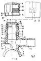
- Fig. 1 shows partially cut and partially in a side view of the tapping fitting with a saddle piece 2 and a tapping piece 4, with which one here exploded cap 6 is connectable.
- the saddle piece according to the invention 2 contains a heating winding in its semi-cylindrical inner surface 8 in a known manner 10, by means of which a welded connection with a not shown here Pipe can be made of plastic, on the cylindrical outer surface of the inner surface the saddle piece 2 is brought to the plant.
- a branch connector 12 opens with which a branch line can be connected.
- a connecting body 14 is provided, which is a spherical Has outer contour, in particular in the form of a ball. With dashed lines 16 is this spherical contour is indicated, the center 18 of which lies on the nozzle axis 20.
- the connector body according to the invention 14 furthermore have an elongated or elliptical contour or similar. Furthermore the connection body can be based on a polygonal contour.
- the connector body 14 also has a number of ribs 22 and grooves 24. In the illustrated Embodiment, the ribs 22 and also the grooves 24 lie in radial planes based on the nozzle axis 22. The bottoms of the grooves 24 are preferably substantially on the outside diameter of the socket 4.
- the connector body instead of the annular ribs and grooves, for example, radial, star-like inward Have recesses or the ribs can have a different orientation to the nozzle axis 20 have. It is essential for all embodiments of the spherical connecting body 14 the reinforcement and stiffening of the connection area, under Avoiding too large a disadvantage in the manufacture of the tapping fitting Material accumulation.
- the connecting body 14 in a particularly expedient manner enables the branch connector with a comparatively large outer diameter to train.
- the branch connector 12 can essentially have the same outer diameter as the pipe to be drilled, on its Outside surface of the saddle piece 2 is attached.
- the said pipe and the connecting line have the same nominal sizes.
- a drill 26 is arranged in the nozzle 4, which in the direction of the nozzle axis 20 is movable. At its first end, which is shown in the starting or End position is in the region of the free end 28 of the nozzle 4, the drill has 26 a contact surface 29 which cooperates with the stop to be explained below. The contact surface 29 is part of the axial end face of the drill 26.
- the drill 26 contains at its free, upper end according to the drawing a radial Extension 30, which is designed in particular as a ring collar. Furthermore the drill 26 has a cylindrical outer surface 32 over its entire length, which one to the cylindrical substantially smooth inner surface 34 of the nozzle 4 Has annular gap 36.
- the drill 26 lies with its contact surface 29, in particular the radial extension 30, on a first stop 38 of the nozzle 4, the first stop 38 has a smaller inner diameter than the radial extension 30.
- the stop 38 is a radially inwardly directed ring collar or web formed. In the factory, the drill 26 is in the position shown in Stub 4 installed, the elastic deformability of the plastic of the tapping fitting allows the insertion of the drill 26 into the socket 4. The attacks 38, 40 prevent the drill 26 from loosening before assembly.
- the upper first stop 38 prevents drilling after returning of the drill 26 in the position shown an inadmissible unscrewing the neck. It is also of particular importance that after the decrease of the schematic indicated drilling device 39 by means of the upper first stop 38 Tearing out the drill 26 from the socket 40 as a result of the drilled in the Pipeline prevailing pressure is prevented and the medium, in particular Gas, can not leak.
- the pressure tapping fitting according to the invention also corresponds low manufacturing and material costs meet the safety requirements for drilling and producing a branch line to a pressurized pipeline. It should be noted that the tapping fitting according to the invention in particular in supply systems for water and gas for the known pressure ranges.
- the socket 4 contains an inside as a locking means second stop 40, which is at a predetermined distance from the first stop 38 is arranged towards the saddle piece 2. Between the two stops 38 and 40 is thus an annular groove 42 for receiving the extension 30 of the drill. With the second stop 40 and the extension 30 a locking is made ensures that an undesirable before assembly and also after drilling Sliding down of the drill 26 is prevented. Especially after tapping is a such sliding down or a movement towards the saddle piece 2 is undesirable, since this results in the mouth 44 of the branch connector 12 from the drill 26 would be closed and the medium no longer properly in the connected line could flow.
- the tapping device 39 with the socket 4, in particular via its external thread 46.
- the tapping device contains a lead screw 47, which with the polygon surfaces 48 at the upper end of Drill 46 can be brought into engagement, so that the drill 26 axially in the nozzle 4 in the direction can be moved to the saddle piece 2 and rotated.
- the second stop 40 points compared to the diameter of the first stop 38 an enlarged diameter such that the extension 30 upon elastic expansion of the second stop 40 can be moved over this.
- Extension 30 is special Expediently designed as a collar, which on the cylindrical inner surface 34 of the connecting piece 4 is preferably sealing.
- the outside diameter of the Annular collar 30 is matched to the inner diameter of the inner surface 34 such that according to the invention a seal and / or good guidance and / or centering in Connection 4 is ensured.
- the lead screw 47 further contains not shown here Means which, for example, engage behind an inner step 49 of the drill 26 in order to the tapping, a return of the drill 26 into the illustrated starting or Allow end position.
- the nozzle 4 further contains viewed in the direction of the saddle piece 2 before the mouth 44 of the branch connector 12 a radially inwardly directed web 50, which abuts the cylindrical outer surface 32 of the drill.
- the web 50 is useful ring-shaped and with its inner diameter on the outer diameter of the drill 26 matched in such a way that guiding and / or sealing is ensured is.
- a double guide or seal is thus provided for the drill 26 on the one hand by the radial extension and / or collar 30 of the drill and on the other hand reached by the radially inward web 50 of the nozzle 4. With low manufacturing and material expenditure is a functional double and axial spaced guidance and / or coverage of the drill 26 also during the Drilling ensured.
- the material combination of the metal drill 26 and the Plastic existing nozzle nevertheless ensures low friction losses and that Tapping can be carried out with comparatively little effort, especially since otherwise between the outer surface 32 of the drill and the inner surface 34 of the The annular gap 36 already explained is present.
- the web 50 according to the invention also as a limitation of the axial feed of the drill 2 when drilling.
- the tapping piece 4 can be closed by means of the cap 6, which in FIG removed position is shown.
- the cap 6 has a cylindrical inside Sealing surface 52, which is associated with a sealing ring 54 of the nozzle 4.
- the sealing surface connects to the bottom 53 inside the cap.
- the sealing ring 54 is in the area of Free end 28 of the nozzle 4 arranged in an outer annular groove 56.
- you can the sealing ring can be arranged in the cap 6, while the associated sealing surface on free end 28 of the nozzle 4 is arranged outside. It is important that the sealing surface 52 is cylindrical, so that the sealing effect is already achieved if the cap 6 is only partially placed on the tapping piece 4.
- the cap 6 has an internal thread in the direction of its open end following the sealing surface 52 58, which can be brought into engagement with the external thread 46 of the socket 4.
- the cap 6 has at least one latching body 62 Locking body 62 expediently has a radially inwardly directed hook 64 on.
- the open end 60 of the cap 6 is provided with a number of slots 66, so that distributed over the circumference a number of said locking body 62 available which is elastically resiliently spread radially outwards.
- a first locking element 68 is assigned to the one or more locking bodies 62 on the outside of the connecting piece 4.
- the locking body 62 and in particular the inner hook 64 is so with its inner diameter on the first locking element 68 matched that the making of the snap connection one requires much greater effort than putting on or screwing on the cap 6.
- the snap connection is designed according to the invention such that the Cap 6 can be moved out of this first latching position again, if necessary to be completely detached from the tapping piece 4.
- the Bring cap 6 into its final and secured position Towards the saddle piece 2, the nozzle 4 has a second locking element 70, which is a larger one Has outer diameter as the first locking element 68. Is the cap 6 in the direction has been moved to the saddle piece 2, there is a further increased resistance overcome until the locking body 62, in particular its hook 64, over the second Locking element 70 is moved away and engages behind it. In the now taken second locking position, the cap 6 is final with respect to the nozzle 4 and permanently secured. The cap 6 can no longer be destroyed by the tapping piece removed and / or turned off.
- the two locking elements 68, 70 there is a further annular groove 72 into which the latching body 62 or the hook 64 engages in said first locking position.
- the depth of the ring groove 72 and / or the outer diameter of the first locking element 68 are on the locking body 62 coordinated such that the cap 6 can be removed again on the one hand, on the other hand can be moved towards the saddle piece 2, after which the to take the second secured stop position.
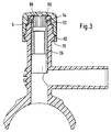
- Fig. 2 shows a further essential embodiment of the tapping fitting
- the Drill 26 assumes a second position in which it is after drilling this tube, not shown.
- the drill 26 contains in the area of its upper
- a seal 82 which is on the cylindrical inner surface 34 of the connector 4 is sealing.
- the seal 82 is an elastomeric sealing ring and / or O-ring formed.
- the drill is used in the Assembly from the inner surface 8 of the saddle piece 2 in the direction of arrow 84 in the Nozzle 4 introduced.
- the elastic seal 82 is easily over the radial inward web 50 of the nozzle 4 when overcoming a predetermined force moved away. When drilling, however, the web 50 forms a sufficient one Limitation of the drill movement.
- the drill 26 has the contact surface 29, which is designed as an annular surface and over which an extension 86 protrudes.
- the approach contains an annular groove 88 on the outside, which is part of the locking means.
- the locking means also contain at the upper, free end at the first stop 38, which in turn is designed as a radially inwardly directed collar, additionally at least one radially inwardly directed nose 90 Several such noses or cams are provided circumferentially.
- the Approach 86 and the annular groove on the one hand and the stop 28 and the lugs or cams 90 on the other are coordinated so that in the upper starting or end position the locking of the drill 26 is ensured.
- Approach 86 is located here within the annular stop 38, the at least one nose 90 in the Ring groove 88 engages.
- Fig. 3 shows the drill 26 in its upper end position after drilling. How mentioned the lugs or cams 90 engage in the annular groove 88 of the drill 26.
- the Cap 6 is screwed tightly onto the neck in the manner described, the Locking body 62 are already pushed over the second locking element 70 and this reach behind, so that the cap 6 assumes its second secured locking position.
- Of the Sealing ring 54 lies on the associated sealing surface 52 in the interior of the cap 6 on.
Abstract
Description
- Fig. 1
- teilweise geschnitten und teilweise in einer seitlichen Ansicht die Anbohrarmatur,
- Fig. 2
- eine weitere Ausführungsform, wobei der Bohrer sich in einer unteren Endposition nach dem Anbohren eines Rohres befindet,
- Fig. 3
- die Anbohrarmatur gemäß Fig. 2, wobei der Bohrer sich in der oberen Grundposition befindet.
- 2
- Sattelstück
- 4
- Anbohrstutzen
- 6
- Kappe
- 8
- Innenfläche
- 10
- Heizwicklung
- 12
- Abzweigstutzen
- 14
- Anschlußkörper
- 16
- gestrichelte Linie
- 18
- Mittelpunkt von 14
- 20
- Stutzenachse
- 22
- Rippe
- 24
- Rille
- 26
- Bohrer
- 28
- freies Ende von 4
- 29
- Anlagefläche von 26
- 30
- radiale Erweiterung von 26
- 32
- Außenfläche von 26
- 34
- Innenfläche von 4
- 36
- Ringspalt
- 38
- erster Anschlag von 4
- 39
- Anbohrvorrichtung
- 40
- zweiter Anschlag von 4
- 42
- Ringnut
- 44
- Mündung von 12
- 46
- Außengewinde
- 47
- Leitspindel
- 48
- Polygonfläche
- 49
- Stufe in 26
- 50
- Steg in 4
- 52
- Dichtfläche
- 53
- Boden von 6
- 54
- Dichtring
- 56
- äußere Ringnut
- 58
- Innengewinde von 6
- 60
- offenes Ende von 6
- 62
- Rastkörper
- 64
- Haken
- 66
- Schlitz
- 68
- erstes Rastelement
- 70
- zweites Rastelement
- 72
- weitere Ringnut
- 80
- Ringnut in 26
- 82
- Dichtung
- 84
- Pfeil
- 86
- Ansatz
- 88
- Ringnut
- 90
- Nase / Nocke
Claims (11)
- Anbohrarmatur, welche mit einem anzubohrenden Rohr, insbesondere durch Schweißen verbindbar ist, enthaltend einen Stutzen (4), in welchem ein Bohrer (26) axial bewegbar angeordnet ist und mit welchem ein Abzweigstutzen (12) verbunden ist, dadurch gekennzeichnet, daß in dem Stutzen (4) der Bohrer (26) unmittelbar geführt ist, daß der Bohrer (26) an seinem oberen, freien Ende eine Erweiterung (30) oder einen Dichtring (54) aufweist, daß die Innenfläche (34) des Stutzens (4) im wesentlichen zylindrisch ausgebildet ist, an welcher der Bohrer (26) mittels der Erweiterung (30) oder dem Dichtring (54) anliegt, und daß der Bohrer (26) mittels einer mit dem Stutzen (4) verbindbaren Anbohrvorrichtung (39) entlang der Innenfläche (34) des Stutzens (4) axial bewegbar ist.
- Anbohrarmatur nach Anspruch, dadurch gekennzeichnet, daß der Stutzen (4) einen ersten Anschlag (38) aufweist, an welchem der Bohrer (26) mittels einer Anlagefläche (29) zur Anlage bringbar ist oder daß die Anlagefläche (29) an der radialen Erweiterung (30) des Bohrers (26) angeordnet ist oder daß an die ringförmig ausgebildete Anlagefläche (29) zum freien Ende ein Ansatz (86) anschließt.
- Anbohrarmatur nach Anspruch 1 oder 2, dadurch gekennzeichnet, daß der Stutzen (4) einen zweiten Anschlag (40) aufweist, über welchen die Erweiterung (30) des Bohrers (26) bei Überwindung einer vorgebbaren Kraft hinwegbewegbar ist und / oder daß axial zwischen dem ersten Anschlag (38) und dem zweiten Anschlag (40) eine Ringnut (42) vorhanden ist, in welche die Erweiterung (30) des Bohrers (26) vor der Montage und / oder nach dem Anbohren angeordnet ist.
- Anbohrarmatur nach Anspruch 2, dadurch gekennzeichnet, daß der erste Anschlag (38) wenigstens eine radial nach innen gerichtete Nocken (90) aufweist und daß der Bohrer (26) im Ansatz (86) eine Ringnut (88) aufweist, in welche die genannte Nocke (90) vor der Montage und / oder nach dem Anbohren eingreift.
- Anbohrarmatur, insbesondere nach einem der Ansprüche 1 bis 4, dadurch gekennzeichnet, daß im Inneren des Stutzens (4) ein radial nach innen gerichteter Steg (50) vorgesehen ist, welcher an der Außenfläche (32) des Bohrers (26) anliegt und / oder daß der Steg (50) im Stutzen (4) oberhalb eines Mündungsbereiches (40) des Abzweigstutzens (12) in den Stutzen (4) angeordnet ist und / oder daß der Steg (50) dichtend an der zylindrischen Außenfläche (32) des Bohrers (26) anliegt.
- Anbohrarmatur nach einem der Ansprüche 1 bis 5, dadurch gekennzeichnet, daß zwischen der zylindrischen Innenfläche (34) und der zylindrischen Außenfläche (32) des Bohrers (26) ein Ringspalt (36) vorgesehen ist, welcher sich in der Ruheposition des Bohrers (26) über einen wesentlichen Teil der Gesamtlänge (26) erstreckt, und / oder daß der Ringspalt (36) axial zwischen der radialen Erweiterung oder den Dichtring (54) des Bohrers (26) und dem genannten radial nach innen gerichteten Steg (50) angeordnet ist.
- Anbohrarmatur. insbesondere nach einem der Ansprüche 1 bis 6, dadurch gekennzeichnet, daß im Anschlußbereich des Abzweigstutzens (12) am Stutzen (4) ein Anschlußkörper (14) vorgesehen ist, welche eine sphärische Kontur, insbesondere einer Kugel oder eines Ellipsoids, aufweist und / oder daß der Anschlußkörper (14) Rippen (22) und / oder Rillen (24) im wesentlichen innerhalb der genannten sphärischen Außenkontur enthält.
- Anbohrarmatur nach Anspruch 7, dadurch gekennzeichnet, daß der Abzweigstutzen (12) zum Anschluß eines derartigen Rohres ausgebildet ist, welches im wesentlichen den gleichen Durchmesser aufweist wie das mittels der Anbohrarmatur anzubohrende Rohr.
- Anbohrarmatur, insbesondere nach einem der Ansprüche 1 bis 8, dadurch gekennzeichnet, daß eine Kappe (6), mittels welcher der Stutzen (4) verschließbar ist, mittels einer Schnappverbindung mit dem Stutzen (4) verbindbar ist, wobei die Kappe (6) und der Stutzen (4) miteinander korrespondierende Rastkörper (62) und Rastelemente (68, 70) aufweisen, und / oder daß die Rastkörper (62) im Bereich des offenen Endes (60) der Kappe (6) angeordnet sind und an ihrer Innenfläche einen Haken (64) aufweisen und / oder daß über den Umfang der Kappe (6) verteilt eine Anzahl derartiger Rastkör per (62) durch Schlitze voneinander getrennt angeordnet sind.
- Anbohrarmatur nach Anspruch 9, dadurch gekennzeichnet, daß der Stutzen (4) ein erstes Rastelement (68) und axial beabstandet ein zweites Rastelement (80) aufweist, wobei zwischen den beiden Rastelementen (68, 70) vorzugsweise eine Ringnut (72) angeordnet ist, daß beim Aufsetzen der Kappe (6) nach Überwinden eines vorgegebenen Widerstandsmoments die Kappe (6) zunächst in eine erste Rastposition bewegbar ist, aus welcher die Kappe (6) wieder herausgelöst werden kann, und daß nach Überwinden eines weiteren, vorzugsweise erhöhten Widerstandsmoments, die Kappe (6) in eine zweite gesicherte Rastposition bewegbar ist, aus welcher die Kappe (6) nicht mehr gelöst werden kann.
- Anbohrarmatur nach Anspruch 9 oder 10, dadurch gekennzeichnet, daß zwischen der Kappe (6) und dem Anbohrstutzen (4) ein Dichtring (54) angeordnet ist, welchem eine zylindrische Dichtfläche (52) zugeordnet ist, und / oder daß die Kappe (6) mit dem Stutzen (4) über eine Gewindeverbindung (46, 58) verbindbar ist und / oder daß das Außengewinde (46) des Stutzens (4) zwischen dessen freien Ende (28) und dem ersten Rastelement (68) vorgesehen ist, und / oder daß der Dichtring (54) im Bereich des freien Endes (28) der Anbohrarmatur und die korrespondierende zylindrische Dichtfläche (52) im Inneren der Kappe (6), insbesondere an deren Boden (53) anschließend, angeordnet ist oder umgekehrt.
Priority Applications (7)
| Application Number | Priority Date | Filing Date | Title |
|---|---|---|---|
| IL12228697A IL122286A (en) | 1996-11-30 | 1997-11-24 | Hose perforation valve |
| US08/979,941 US5975117A (en) | 1996-11-30 | 1997-11-26 | Pipe fitting for drilling |
| PL97323408A PL185828B1 (pl) | 1996-11-30 | 1997-11-28 | Urządzenie do nawiercaniaUrządzenie do nawiercania |
| ARP970105608 AR010075A1 (es) | 1996-11-30 | 1997-11-28 | Valvula de cierre |
| TR97/01457A TR199701457A2 (xx) | 1996-11-30 | 1997-11-28 | Burgu armat�r� |
| CN97126374A CN1102874C (zh) | 1996-11-30 | 1997-11-29 | 管子钻孔配件 |
| JP32993597A JP4101337B2 (ja) | 1996-11-30 | 1997-12-01 | ドリル加工バルブ |
Applications Claiming Priority (2)
| Application Number | Priority Date | Filing Date | Title |
|---|---|---|---|
| DE1996149731 DE19649731C2 (de) | 1996-11-30 | 1996-11-30 | Anbohrarmatur |
| DE19649731 | 1996-11-30 |
Publications (2)
| Publication Number | Publication Date |
|---|---|
| EP0845630A2 true EP0845630A2 (de) | 1998-06-03 |
| EP0845630A3 EP0845630A3 (de) | 2003-12-17 |
Family
ID=7813263
Family Applications (1)
| Application Number | Title | Priority Date | Filing Date |
|---|---|---|---|
| EP97118520A Withdrawn EP0845630A3 (de) | 1996-11-30 | 1997-10-24 | Anbohrarmatur |
Country Status (3)
| Country | Link |
|---|---|
| EP (1) | EP0845630A3 (de) |
| AR (1) | AR010075A1 (de) |
| DE (1) | DE19649731C2 (de) |
Cited By (4)
| Publication number | Priority date | Publication date | Assignee | Title |
|---|---|---|---|---|
| WO2001096778A3 (de) * | 2000-06-16 | 2002-05-16 | Friatec Ag | Anbohrarmatur |
| DE10202676C1 (de) * | 2002-01-23 | 2003-04-24 | Friatec Ag | Armatur |
| DE10310171A1 (de) * | 2003-01-24 | 2004-08-19 | Friatec Ag | Anbohrarmatur |
| DE102007045431A1 (de) | 2007-09-22 | 2009-04-02 | Egeplast Werner Strumann Gmbh & Co. Kg | Anbohrarmatur |
Families Citing this family (1)
| Publication number | Priority date | Publication date | Assignee | Title |
|---|---|---|---|---|
| DE102004057898A1 (de) * | 2004-12-01 | 2006-06-08 | Wilhelm Karmann Gmbh | Kraftfahrzeug mit zumindest einem absenkbaren Dachteil |
Citations (3)
| Publication number | Priority date | Publication date | Assignee | Title |
|---|---|---|---|---|
| EP0024741A2 (de) * | 1979-09-03 | 1981-03-11 | Bopp & Reuther Aktiengesellschaft | Ventilanbohrarmatur |
| DE3830395C1 (en) * | 1988-09-07 | 1990-01-11 | Friedrichsfeld Gmbh Keramik- Und Kunststoffwerke, 6800 Mannheim, De | Boring fitting |
| WO1995016874A1 (de) * | 1993-12-14 | 1995-06-22 | Wavin B.V. | Verfahren zum anbohren einer leitung |
Family Cites Families (2)
| Publication number | Priority date | Publication date | Assignee | Title |
|---|---|---|---|---|
| CA1037512A (en) * | 1974-08-12 | 1978-08-29 | Thomas Pessia | Tapping t for plastic pipe |
| DE4039353C1 (en) * | 1990-12-10 | 1992-03-05 | Friedrichsfeld Ag Keramik- Und Kunststoffwerke, 6800 Mannheim, De | Closing of damaged plastics pipe - involves plug screwed into side of pipe from housing fitted on outside |
-
1996
- 1996-11-30 DE DE1996149731 patent/DE19649731C2/de not_active Expired - Fee Related
-
1997
- 1997-10-24 EP EP97118520A patent/EP0845630A3/de not_active Withdrawn
- 1997-11-28 AR ARP970105608 patent/AR010075A1/es unknown
Patent Citations (3)
| Publication number | Priority date | Publication date | Assignee | Title |
|---|---|---|---|---|
| EP0024741A2 (de) * | 1979-09-03 | 1981-03-11 | Bopp & Reuther Aktiengesellschaft | Ventilanbohrarmatur |
| DE3830395C1 (en) * | 1988-09-07 | 1990-01-11 | Friedrichsfeld Gmbh Keramik- Und Kunststoffwerke, 6800 Mannheim, De | Boring fitting |
| WO1995016874A1 (de) * | 1993-12-14 | 1995-06-22 | Wavin B.V. | Verfahren zum anbohren einer leitung |
Cited By (8)
| Publication number | Priority date | Publication date | Assignee | Title |
|---|---|---|---|---|
| WO2001096778A3 (de) * | 2000-06-16 | 2002-05-16 | Friatec Ag | Anbohrarmatur |
| US6758237B2 (en) | 2000-06-16 | 2004-07-06 | Friatec Aktiengesellschaft | Tapping valve |
| DE10202676C1 (de) * | 2002-01-23 | 2003-04-24 | Friatec Ag | Armatur |
| US7246634B2 (en) | 2002-01-23 | 2007-07-24 | Friatec Aktiengesellschaft | Drill for tapping pipe with safety device in branch pipe |
| DE10310171A1 (de) * | 2003-01-24 | 2004-08-19 | Friatec Ag | Anbohrarmatur |
| DE10310171B4 (de) * | 2003-01-24 | 2006-09-07 | Friatec Ag | Anbohrarmatur |
| DE102007045431A1 (de) | 2007-09-22 | 2009-04-02 | Egeplast Werner Strumann Gmbh & Co. Kg | Anbohrarmatur |
| EP2048426A2 (de) | 2007-09-22 | 2009-04-15 | Egeplast Werner Strumann GmbH & Co. KG | Anbohrarmatur |
Also Published As
| Publication number | Publication date |
|---|---|
| EP0845630A3 (de) | 2003-12-17 |
| DE19649731C2 (de) | 1999-04-29 |
| AR010075A1 (es) | 2000-05-17 |
| DE19649731A1 (de) | 1998-06-04 |
Similar Documents
| Publication | Publication Date | Title |
|---|---|---|
| EP0572817B2 (de) | Anbohrarmatur und Ventil | |
| EP1290371B1 (de) | Anbohrarmatur | |
| DE2521930C2 (de) | Rohrverbindungsstück | |
| DE3830395C1 (en) | Boring fitting | |
| DE3604194A1 (de) | Stopfen fuer waermetauscherrohre oder -leitungen | |
| EP0327494B1 (de) | Steckbare Sicherheitskupplung, insbesondere für Druckluftleitungen | |
| DE19531913C2 (de) | Kombinierte Anbohr- und Ventilanbohrarmatur für, insbesondere unter Mediendruck stehende, Versorgungsleitungen aus Kunststoff | |
| DE60107117T2 (de) | Anbohranschlussstück | |
| DE3308877C2 (de) | ||
| EP0845630A2 (de) | Anbohrarmatur | |
| DE4309941C2 (de) | Anbohrarmatur | |
| EP0736718B1 (de) | Anbohrarmatur für vorzugsweise unter Mediendruck stehende Versorgungsleitungen aus Kunststoff | |
| DE4304954A1 (de) | Anbohrschelle aus Kunststoff mit einer Bohrbüchse | |
| EP2137447B1 (de) | Kurzbauender stecker für fluidkupplungen | |
| DE102005008398B4 (de) | Anbohrarmatur für Kunststoffrohre und Verfahren zum Anschließen einer Anbohrarmatur | |
| DE3723898A1 (de) | Anbohrarmatur | |
| DE19629459C2 (de) | Anbohrarmatur für Kunststoffrohre | |
| EP0811799A2 (de) | Ventil-Anbohrarmatur für vorzugsweise unter Mediendruck stehende Versorgungsleitungen aus Kunststoff | |
| DE10302917B3 (de) | Ventil-Anbohrarmatur | |
| EP0821193B1 (de) | Anbohrarmatur für Kunststoffrohre | |
| DE4426445C3 (de) | Schneidring | |
| DE4244741C2 (de) | Montagevorrichtung für eine Schutzbuchse zur Vermeidung von Inkrustationen im Bereich einer durch eine Anbohrarmatur hergestellten Bohrung | |
| DE19630028C2 (de) | Ventilanbohrarmatur für vorzugsweise unter Mediendruck stehende Versorgungsleitungen aus Kunststoff | |
| DE4039353C1 (en) | Closing of damaged plastics pipe - involves plug screwed into side of pipe from housing fitted on outside | |
| DE10310171B4 (de) | Anbohrarmatur |
Legal Events
| Date | Code | Title | Description |
|---|---|---|---|
| PUAI | Public reference made under article 153(3) epc to a published international application that has entered the european phase |
Free format text: ORIGINAL CODE: 0009012 |
|
| AK | Designated contracting states |
Kind code of ref document: A2 Designated state(s): AT BE CH DE DK ES FI FR GB GR IE IT LI LU MC NL PT SE |
|
| AX | Request for extension of the european patent |
Free format text: AL;LT;LV;RO;SI |
|
| RIN1 | Information on inventor provided before grant (corrected) |
Inventor name: SCHOLL, REINHOLD Inventor name: KRETZ, STEFFEN Inventor name: SICHLER, WOLFGANG Inventor name: SCHWEITZER, RUEDIGER |
|
| PUAL | Search report despatched |
Free format text: ORIGINAL CODE: 0009013 |
|
| AK | Designated contracting states |
Kind code of ref document: A3 Designated state(s): AT BE CH DE DK ES FI FR GB GR IE IT LI LU MC NL PT SE |
|
| AX | Request for extension of the european patent |
Extension state: AL LT LV RO SI |
|
| RIC1 | Information provided on ipc code assigned before grant |
Ipc: 7F 16L 41/08 B Ipc: 7F 16L 47/02 B Ipc: 7F 16L 47/00 A |
|
| 17P | Request for examination filed |
Effective date: 20040527 |
|
| AKX | Designation fees paid |
Designated state(s): AT CH DE ES FR GB IT LI MC |
|
| 17Q | First examination report despatched |
Effective date: 20050401 |
|
| GRAP | Despatch of communication of intention to grant a patent |
Free format text: ORIGINAL CODE: EPIDOSNIGR1 |
|
| STAA | Information on the status of an ep patent application or granted ep patent |
Free format text: STATUS: THE APPLICATION IS DEEMED TO BE WITHDRAWN |
|
| 18D | Application deemed to be withdrawn |
Effective date: 20060412 |