EP0845630A2 - Tapping apparatus - Google Patents
Tapping apparatus Download PDFInfo
- Publication number
- EP0845630A2 EP0845630A2 EP97118520A EP97118520A EP0845630A2 EP 0845630 A2 EP0845630 A2 EP 0845630A2 EP 97118520 A EP97118520 A EP 97118520A EP 97118520 A EP97118520 A EP 97118520A EP 0845630 A2 EP0845630 A2 EP 0845630A2
- Authority
- EP
- European Patent Office
- Prior art keywords
- drill
- cap
- tapping
- nozzle
- tapping fitting
- Prior art date
- Legal status (The legal status is an assumption and is not a legal conclusion. Google has not performed a legal analysis and makes no representation as to the accuracy of the status listed.)
- Withdrawn
Links
Images

Classifications
-
- F—MECHANICAL ENGINEERING; LIGHTING; HEATING; WEAPONS; BLASTING
- F16—ENGINEERING ELEMENTS AND UNITS; GENERAL MEASURES FOR PRODUCING AND MAINTAINING EFFECTIVE FUNCTIONING OF MACHINES OR INSTALLATIONS; THERMAL INSULATION IN GENERAL
- F16L—PIPES; JOINTS OR FITTINGS FOR PIPES; SUPPORTS FOR PIPES, CABLES OR PROTECTIVE TUBING; MEANS FOR THERMAL INSULATION IN GENERAL
- F16L47/00—Connecting arrangements or other fittings specially adapted to be made of plastics or to be used with pipes made of plastics
- F16L47/26—Connecting arrangements or other fittings specially adapted to be made of plastics or to be used with pipes made of plastics for branching pipes; for joining pipes to walls; Adaptors therefor
- F16L47/34—Tapping pipes, i.e. making connections through walls of pipes while carrying fluids; Fittings therefor
Definitions
- the invention relates to a tapping fitting according to the in the preamble of Features specified claim 1.
- Such a tapping fitting is known from the patent DE 38 30 395 C1 and is can be connected to a pipe to be drilled out of plastic, in particular by welding.
- the tapping fitting contains a socket in which a for drilling the Tube trained drill is axially movable.
- the drill points into that mentioned internal thread engaging external thread and an internal hexagon for a tool on. When the tool is turned, the drill experiences one axial feed for drilling through the wall of the connected to the tapping fitting Tube.
- There is further provided at least one sealing ring to one after drilling Prevent the medium flowing through the pipe from escaping.
- This tapping valve has proven to be very useful in many applications, but requires a certain amount of material and manufacturing.
- the upper part contains a nozzle with which a housing one Tapping device can be connected via a thread.
- the tapping device contains one Threaded spindle, whose external thread engages in an internal thread of the housing. With the threaded spindle can be connected to a drill, which at the same time acts as a closure piece is trained. When turning the threaded spindle, this is experienced just like the coupled one Drill an axial feed to drill into the plastic pipe.
- the drill contains an external thread, which anchors the drill after drilling or locking piece in the pipe guaranteed. After drilling, the non-rotatable Connection of the drill released from the threaded spindle and the housing from the upper part removed, the drill remains as a closure piece in the tube.
- a tapping fitting made of plastic is known from US Pat. No. 4,063,844, whose socket contains an internal thread for the drill.
- the drill also has one The hexagon socket for an Allen key and turning it turns the Drill the axial feed, whereby considerable torque is applied got to.
- the internal thread of the nozzle extends over its entire length and after the pipe has been drilled, the seal is only made using the threaded connection of drill and socket. A not inconsiderable leakage must be expected which is particularly undesirable in gas pipelines.
- the tapping piece should one Appropriate sealing during tapping and after Have tapping.
- the tapping piece should allow easy handling and ensure a secure seal after drilling for a long service life. After all, the tapping fitting should require little material.
- the proposed plastic tapping fitting is characterized by a functional Construction and ensures sealing with little effort in the tapping area both during tapping and subsequently during one long lifespan of many decades.
- the neck essentially contains one cylindrical and / or smooth inner surface without thread and consists of Plastic without guide sleeve made of metal.
- the drill contains free at its top End a radial extension or a sealing ring, the extension or the Place the sealing ring on the smooth cylindrical inner surface of the socket. This will a guide and / or a reliable seal between the drill and socket reached.
- the drill advances axially by means of a connector which can be connected to the socket external tapping device.
- the connector expediently contains a stop, by means of which loosening of the drill is prevented.
- the stop is in particular an integral part of the nozzle and / or in one piece with it Made of plastic.
- the preferably annular stop has one smaller inner diameter than that in the direction of the pipe cylindrical inner surface of the nozzle.
- the drill has in particular on its Pipe facing away from the free end of a counter surface, which is used to abut the aforementioned Stop of the nozzle can be brought.
- the counter surface is preferably an axial end surface a radial expansion, in particular in the form of a ring collar, which initially abuts the first stop mentioned and / or in an adjacent one engages the first stop arranged annular groove. Conveniently closes a second stop on the ring groove, namely towards the pipe side, which First, the drill is locked in conjunction with the extension mentioned enables.
- this is the first stop mentioned assigned contact surface of the drill formed as an annular surface, which is preferred surrounds a shoulder of the drill at its free upper end.
- the annular and radially inwardly directed first stop also at least one inward nose, which in a circumferential groove of the drill or its mentioned approach engages and thus locks the drill in the upper end position.
- the drill contains, expediently in its upper one End area a seal, which on the cylindrical inner surface of the nozzle fits tightly.
- the drill is moreover one essential part of its total length is also cylindrical.
- the drill according to the invention from the inside or the inside surface of the tapping fitting assembly in the socket and as far as the upper end facing away from the pipe pushed into the socket until the contact surface lies against the stop of the socket and / or the lock is made.
- locking means are provided, which especially as the mentioned annular groove between the two stops or as the engaging nose are formed in an annular groove of the drill.
- the axial feed is applied by an external tapping device, which in is known to be engageable with the nozzle and the drill.
- an external tapping device Internally of the connector is above an opening of a branch connector in the connector there is a radially inwardly directed web, which is on the cylindrical outer surface of the drill.
- This web serves in an expedient manner to guide the drill, wherein, moreover, between the outer surface of the drill and the inner surface of the A predetermined annular gap is present.
- the web can be used for guiding into individual segments distributed over the circumference be divided.
- the web is over the Scope formed as a closed ring, which seals the cylindrical The outer surface of the drill rests.
- the web and the cylindrical outer surface of the drill are coordinated so that a seal is guaranteed, the Spring elasticity of the plastic of the tapping fitting is taken into account.
- said locking means an undesirable sliding or even prevent the branch connector from closing.
- the tapping fitting has a cap closable, which can be connected to the nozzle via a snap lock.
- the cap is removed placed on the free end of the socket, in particular screwed on, until a locking body the cap is engaged with a locking element of the nozzle.
- a predetermined resistance in particular screw-in resistance, be overcome.
- the cap can Needs to be resolved again.
- a sealing element in particular a sealing ring, is provided, which at Placing the cap on the free nozzle end ensures a seal and this maintained in the first rest position.
- the neck also has a second locking element with which the locking body after a further axial movement, in particular screw-on movement, can be brought into engagement in a second latching position.
- the second locking element is matched to the locking body of the cap so that it cannot be removed from the nozzle without being destroyed. After graduation All work to connect a branch line is the cap in the second Rested position transferred, so that subsequently the seal is permanent and reliable the pipe socket is guaranteed, and an unintentional and / or undesirable Loosening the cap is prevented.
- connection area of the branch connector in the connection area of the branch connector the tapping piece with a spherical body like a sphere or an egg or the like.
- connection area of the nozzle only as one cylindrical extension, that is, with an increased wall thickness.
- connection area can be provided in a convenient manner ribs, the outer surfaces preferably lie within the spherical contour of the connecting body.
- the body is an integral part the tapping valve made of plastic. Because of the connector body is in particularly expediently allows the branch connector for the same Nominal size is designed like the one to be drilled or drilled using the tapping fitting Pipe. With the previous tapping fittings, only branch pipes could be connected to the pipe with reduced nominal dimensions.
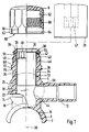
- Fig. 1 shows partially cut and partially in a side view of the tapping fitting with a saddle piece 2 and a tapping piece 4, with which one here exploded cap 6 is connectable.
- the saddle piece according to the invention 2 contains a heating winding in its semi-cylindrical inner surface 8 in a known manner 10, by means of which a welded connection with a not shown here Pipe can be made of plastic, on the cylindrical outer surface of the inner surface the saddle piece 2 is brought to the plant.
- a branch connector 12 opens with which a branch line can be connected.
- a connecting body 14 is provided, which is a spherical Has outer contour, in particular in the form of a ball. With dashed lines 16 is this spherical contour is indicated, the center 18 of which lies on the nozzle axis 20.
- the connector body according to the invention 14 furthermore have an elongated or elliptical contour or similar. Furthermore the connection body can be based on a polygonal contour.
- the connector body 14 also has a number of ribs 22 and grooves 24. In the illustrated Embodiment, the ribs 22 and also the grooves 24 lie in radial planes based on the nozzle axis 22. The bottoms of the grooves 24 are preferably substantially on the outside diameter of the socket 4.
- the connector body instead of the annular ribs and grooves, for example, radial, star-like inward Have recesses or the ribs can have a different orientation to the nozzle axis 20 have. It is essential for all embodiments of the spherical connecting body 14 the reinforcement and stiffening of the connection area, under Avoiding too large a disadvantage in the manufacture of the tapping fitting Material accumulation.
- the connecting body 14 in a particularly expedient manner enables the branch connector with a comparatively large outer diameter to train.
- the branch connector 12 can essentially have the same outer diameter as the pipe to be drilled, on its Outside surface of the saddle piece 2 is attached.
- the said pipe and the connecting line have the same nominal sizes.
- a drill 26 is arranged in the nozzle 4, which in the direction of the nozzle axis 20 is movable. At its first end, which is shown in the starting or End position is in the region of the free end 28 of the nozzle 4, the drill has 26 a contact surface 29 which cooperates with the stop to be explained below. The contact surface 29 is part of the axial end face of the drill 26.
- the drill 26 contains at its free, upper end according to the drawing a radial Extension 30, which is designed in particular as a ring collar. Furthermore the drill 26 has a cylindrical outer surface 32 over its entire length, which one to the cylindrical substantially smooth inner surface 34 of the nozzle 4 Has annular gap 36.
- the drill 26 lies with its contact surface 29, in particular the radial extension 30, on a first stop 38 of the nozzle 4, the first stop 38 has a smaller inner diameter than the radial extension 30.
- the stop 38 is a radially inwardly directed ring collar or web formed. In the factory, the drill 26 is in the position shown in Stub 4 installed, the elastic deformability of the plastic of the tapping fitting allows the insertion of the drill 26 into the socket 4. The attacks 38, 40 prevent the drill 26 from loosening before assembly.
- the upper first stop 38 prevents drilling after returning of the drill 26 in the position shown an inadmissible unscrewing the neck. It is also of particular importance that after the decrease of the schematic indicated drilling device 39 by means of the upper first stop 38 Tearing out the drill 26 from the socket 40 as a result of the drilled in the Pipeline prevailing pressure is prevented and the medium, in particular Gas, can not leak.
- the pressure tapping fitting according to the invention also corresponds low manufacturing and material costs meet the safety requirements for drilling and producing a branch line to a pressurized pipeline. It should be noted that the tapping fitting according to the invention in particular in supply systems for water and gas for the known pressure ranges.
- the socket 4 contains an inside as a locking means second stop 40, which is at a predetermined distance from the first stop 38 is arranged towards the saddle piece 2. Between the two stops 38 and 40 is thus an annular groove 42 for receiving the extension 30 of the drill. With the second stop 40 and the extension 30 a locking is made ensures that an undesirable before assembly and also after drilling Sliding down of the drill 26 is prevented. Especially after tapping is a such sliding down or a movement towards the saddle piece 2 is undesirable, since this results in the mouth 44 of the branch connector 12 from the drill 26 would be closed and the medium no longer properly in the connected line could flow.
- the tapping device 39 with the socket 4, in particular via its external thread 46.
- the tapping device contains a lead screw 47, which with the polygon surfaces 48 at the upper end of Drill 46 can be brought into engagement, so that the drill 26 axially in the nozzle 4 in the direction can be moved to the saddle piece 2 and rotated.
- the second stop 40 points compared to the diameter of the first stop 38 an enlarged diameter such that the extension 30 upon elastic expansion of the second stop 40 can be moved over this.
- Extension 30 is special Expediently designed as a collar, which on the cylindrical inner surface 34 of the connecting piece 4 is preferably sealing.
- the outside diameter of the Annular collar 30 is matched to the inner diameter of the inner surface 34 such that according to the invention a seal and / or good guidance and / or centering in Connection 4 is ensured.
- the lead screw 47 further contains not shown here Means which, for example, engage behind an inner step 49 of the drill 26 in order to the tapping, a return of the drill 26 into the illustrated starting or Allow end position.
- the nozzle 4 further contains viewed in the direction of the saddle piece 2 before the mouth 44 of the branch connector 12 a radially inwardly directed web 50, which abuts the cylindrical outer surface 32 of the drill.
- the web 50 is useful ring-shaped and with its inner diameter on the outer diameter of the drill 26 matched in such a way that guiding and / or sealing is ensured is.
- a double guide or seal is thus provided for the drill 26 on the one hand by the radial extension and / or collar 30 of the drill and on the other hand reached by the radially inward web 50 of the nozzle 4. With low manufacturing and material expenditure is a functional double and axial spaced guidance and / or coverage of the drill 26 also during the Drilling ensured.
- the material combination of the metal drill 26 and the Plastic existing nozzle nevertheless ensures low friction losses and that Tapping can be carried out with comparatively little effort, especially since otherwise between the outer surface 32 of the drill and the inner surface 34 of the The annular gap 36 already explained is present.
- the web 50 according to the invention also as a limitation of the axial feed of the drill 2 when drilling.
- the tapping piece 4 can be closed by means of the cap 6, which in FIG removed position is shown.
- the cap 6 has a cylindrical inside Sealing surface 52, which is associated with a sealing ring 54 of the nozzle 4.
- the sealing surface connects to the bottom 53 inside the cap.
- the sealing ring 54 is in the area of Free end 28 of the nozzle 4 arranged in an outer annular groove 56.
- you can the sealing ring can be arranged in the cap 6, while the associated sealing surface on free end 28 of the nozzle 4 is arranged outside. It is important that the sealing surface 52 is cylindrical, so that the sealing effect is already achieved if the cap 6 is only partially placed on the tapping piece 4.
- the cap 6 has an internal thread in the direction of its open end following the sealing surface 52 58, which can be brought into engagement with the external thread 46 of the socket 4.
- the cap 6 has at least one latching body 62 Locking body 62 expediently has a radially inwardly directed hook 64 on.
- the open end 60 of the cap 6 is provided with a number of slots 66, so that distributed over the circumference a number of said locking body 62 available which is elastically resiliently spread radially outwards.
- a first locking element 68 is assigned to the one or more locking bodies 62 on the outside of the connecting piece 4.
- the locking body 62 and in particular the inner hook 64 is so with its inner diameter on the first locking element 68 matched that the making of the snap connection one requires much greater effort than putting on or screwing on the cap 6.
- the snap connection is designed according to the invention such that the Cap 6 can be moved out of this first latching position again, if necessary to be completely detached from the tapping piece 4.
- the Bring cap 6 into its final and secured position Towards the saddle piece 2, the nozzle 4 has a second locking element 70, which is a larger one Has outer diameter as the first locking element 68. Is the cap 6 in the direction has been moved to the saddle piece 2, there is a further increased resistance overcome until the locking body 62, in particular its hook 64, over the second Locking element 70 is moved away and engages behind it. In the now taken second locking position, the cap 6 is final with respect to the nozzle 4 and permanently secured. The cap 6 can no longer be destroyed by the tapping piece removed and / or turned off.
- the two locking elements 68, 70 there is a further annular groove 72 into which the latching body 62 or the hook 64 engages in said first locking position.
- the depth of the ring groove 72 and / or the outer diameter of the first locking element 68 are on the locking body 62 coordinated such that the cap 6 can be removed again on the one hand, on the other hand can be moved towards the saddle piece 2, after which the to take the second secured stop position.
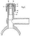
- Fig. 2 shows a further essential embodiment of the tapping fitting
- the Drill 26 assumes a second position in which it is after drilling this tube, not shown.
- the drill 26 contains in the area of its upper
- a seal 82 which is on the cylindrical inner surface 34 of the connector 4 is sealing.
- the seal 82 is an elastomeric sealing ring and / or O-ring formed.
- the drill is used in the Assembly from the inner surface 8 of the saddle piece 2 in the direction of arrow 84 in the Nozzle 4 introduced.
- the elastic seal 82 is easily over the radial inward web 50 of the nozzle 4 when overcoming a predetermined force moved away. When drilling, however, the web 50 forms a sufficient one Limitation of the drill movement.
- the drill 26 has the contact surface 29, which is designed as an annular surface and over which an extension 86 protrudes.
- the approach contains an annular groove 88 on the outside, which is part of the locking means.
- the locking means also contain at the upper, free end at the first stop 38, which in turn is designed as a radially inwardly directed collar, additionally at least one radially inwardly directed nose 90 Several such noses or cams are provided circumferentially.
- the Approach 86 and the annular groove on the one hand and the stop 28 and the lugs or cams 90 on the other are coordinated so that in the upper starting or end position the locking of the drill 26 is ensured.
- Approach 86 is located here within the annular stop 38, the at least one nose 90 in the Ring groove 88 engages.
- Fig. 3 shows the drill 26 in its upper end position after drilling. How mentioned the lugs or cams 90 engage in the annular groove 88 of the drill 26.
- the Cap 6 is screwed tightly onto the neck in the manner described, the Locking body 62 are already pushed over the second locking element 70 and this reach behind, so that the cap 6 assumes its second secured locking position.
- Of the Sealing ring 54 lies on the associated sealing surface 52 in the interior of the cap 6 on.
Abstract
Description
Die Erfindung bezieht sich auf eine Anbohrarmatur gemäß den im Oberbegriff des Patentanspruchs 1 angegebenen Merkmalen.The invention relates to a tapping fitting according to the in the preamble of Features specified claim 1.
Eine derartige Anbohrarmatur ist aus der Patentschrift DE 38 30 395 C1 bekannt und ist
mit einem anzubohrenden Rohr aus Kunststoff, insbesondere durch Schweißen, verbindbar.
Die Anbohrarmatur enthält einen Stutzen, in welchem ein für das Anbohren des
Rohres ausgebildeter Bohrer axial bewegbar angeordnet ist. In den Stutzen ist eine
Hülse mit einem Innengewinde dicht und drehfest integriert. Der Bohrer weist ein in das
genannte Innengewinde eingreifendes Außengewinde sowie einen Innensechskant für
ein Werkzeug auf. Beim Drehen des eingesetzten Werkzeuges erfährt der Bohrer einen
axialen Vorschub zum Durchbohren der Wand des mit der Anbohrarmatur verbundenen
Rohres. Es ist ferner wenigstens ein Dichtring vorgesehen, um nach dem Anbohren ein
Austreten des durch das Rohr strömenden Mediums zu unterbinden. Diese Anbohrarmatur
hat sich in vielen Anwendungsfällen als sehr zweckmäßig erwiesen, erfordert aber
einen gewissen Material- und Fertigungsaufwand.Such a tapping fitting is known from the
Aus der Patentschrift DE 40 39 353 C1 ist eine Anordnung zum Verschließen einer
Rohrleitung bekannt, auf deren Außenfläche ein Oberteil, insbesondere eine Metallschelle
festlegbar ist. Das Oberteil enthält einen Stutzen, mit welchem ein Gehäuse einer
Anbohrvorrichtung über ein Gewinde verbindbar ist. Die Anbohrvorrichtung enthält eine
Gewindespindel, deren Außengewinde in ein Innengewinde des Gehäuses eingreift. Mit
der Gewindespindel ist ein Bohrer verbindbar, welcher gleichzeitig als Verschlußstück
ausgebildet ist. Beim Drehen der Gewindespindel erfährt diese ebenso wie der angekoppelte
Bohrer einen axialen Vorschub, um das Kunststoffrohr anzubohren. Der Bohrer
enthält ein Außengewinde, welches nach dem Anbohren eine Verankerung des Bohrers
bzw. Verschlußstückes im Rohr gewährleistet. Nach dem Anbohren wird die drehfeste
Verbindung des Bohrers von der Gewindespindel gelöst und das Gehäuse vom Oberteil
entfernt, wobei der Bohrer als Verschlußstück im Rohr verbleibt.From the
Ferner ist aus dem US-Patent 40 63 844 eine Anbohrarmatur aus Kunststoff bekannt, deren Stutzen ein Innengewinde für den Bohrer enthält. Der Bohrer besitzt ferner einen Innensechskant für einen Imbusschlüssel und durch Drehen desselben erfährt der Bohrer den axialen Vorschub, wobei ein erhebliches Drehmoment aufgebracht werden muß. Das Innengewinde des Stutzens erstreckt sich über dessen gesamte Länge und nach dem Anbohren des Rohres erfolgt die Abdichtung lediglich über die Gewindeverbindung von Bohrer und Stutzen. Es muß mit einer nicht unerheblichen Leckage gerechnet werden, welche vor allem bei gasführenden Rohrleitungen unerwünscht ist.Furthermore, a tapping fitting made of plastic is known from US Pat. No. 4,063,844, whose socket contains an internal thread for the drill. The drill also has one The hexagon socket for an Allen key and turning it turns the Drill the axial feed, whereby considerable torque is applied got to. The internal thread of the nozzle extends over its entire length and after the pipe has been drilled, the seal is only made using the threaded connection of drill and socket. A not inconsiderable leakage must be expected which is particularly undesirable in gas pipelines.
Hiervon ausgehend liegt der Erfindung die Aufgabe zugrunde, die Anbohrarmatur der genannten Art dahingehend weiterzubilden, daß mit geringem Fertigungsaufwand das Anbohren des Rohres funktionssicher durchführbar ist. Das Anbohrstück soll eine den Anforderungen entsprechende Abdichtung während des Anbohrens und nach dem Anbohren aufweisen. Das Anbohrstück soll eine einfache Handhabung ermöglichen und nach dem Anbohren für eine lange Lebensdauer einer sichere Abdichtung gewährleisten. Schließlich soll die Anbohrarmatur einen geringen Materialaufwand erfordern.Proceeding from this, the invention is based on the object of the tapping fitting mentioned type to the extent that the Drilling the pipe is functionally feasible. The tapping piece should one Appropriate sealing during tapping and after Have tapping. The tapping piece should allow easy handling and ensure a secure seal after drilling for a long service life. After all, the tapping fitting should require little material.
Die Lösung dieser Aufgabe erfolgt gemäß den im Patentanspruch 1 angegebenen Merkmalen.This object is achieved according to the features specified in claim 1.
Die vorgeschlagene Kunststoff-Anbohrarmatur zeichnet sich durch eine funktionsgerechte Konstruktion aus und gewährleistet mit geringem Aufwand die Abdichtung im Anbohrbereich sowohl während des Anbohrens als auch nachfolgend während einer langen Lebensdauer von vielen Jahrzehnten. Der Stutzen enthält eine im wesentlichen zylindrisch ausgebildete und / oder glatte Innenfläche ohne Gewinde und besteht aus Kunststoff ohne Führungshülse aus Metall. Der Bohrer enthält an seinem oberen freien Ende eine radiale Erweiterung oder einen Dichtring, wobei die Erweiterung oder der Dichtring an der glatten zylindrischen Innenfläche des Stutzens anliegen. Hierdurch wird eine Führung und / oder eine funktionssichere Abdichtung zwischen Bohrer und Stutzen erreicht. Der axiale Vorschub des Bohrers erfolgt mittels einer mit dem Stutzen verbindbaren externen Anbohrvorrichtung. Zweckmäßig enthält der Stutzen einen Anschlag, mittels welchem ein Herauslösen des Bohrers unterbunden wird. Der Anschlag ist insbesondere integraler Bestandteil des Stutzens und / oder einteilig mit diesen aus Kunststoff gefertigt. Der vorzugsweise ringförmig ausgebildete Anschlag weist einen kleineren Innendurchmesser auf als die in Richtung zum Rohr sich anschließende zylindrische Innenfläche des Stutzens. Der Bohrer besitzt insbesondere an seinem dem Rohr abgewandten freien Ende eine Gegenfläche, welche zur Anlage an den genannten Anschlag des Stutzens bringbar ist. Die Gegenfläche ist vorzugsweise als axiale Stirnfläche einer radialen Erweiterung, insbesondere in Form eines Ringbundes ausgebildet, welcher zunächst an dem genannten ersten Anschlag anliegt und / oder in eine benachbartzum ersten Anschlag angeordnete Ringnut eingreift. In zweckmäßiger Weise schließt an die Ringnut, und zwar in Richtung zur Rohrseite, ein zweiter Anschlag an, welcher zunächst eine Arretierung des Bohrers im Zusammenspiel mit der genannten Erweiterung ermöglicht.The proposed plastic tapping fitting is characterized by a functional Construction and ensures sealing with little effort in the tapping area both during tapping and subsequently during one long lifespan of many decades. The neck essentially contains one cylindrical and / or smooth inner surface without thread and consists of Plastic without guide sleeve made of metal. The drill contains free at its top End a radial extension or a sealing ring, the extension or the Place the sealing ring on the smooth cylindrical inner surface of the socket. This will a guide and / or a reliable seal between the drill and socket reached. The drill advances axially by means of a connector which can be connected to the socket external tapping device. The connector expediently contains a stop, by means of which loosening of the drill is prevented. The stop is in particular an integral part of the nozzle and / or in one piece with it Made of plastic. The preferably annular stop has one smaller inner diameter than that in the direction of the pipe cylindrical inner surface of the nozzle. The drill has in particular on its Pipe facing away from the free end of a counter surface, which is used to abut the aforementioned Stop of the nozzle can be brought. The counter surface is preferably an axial end surface a radial expansion, in particular in the form of a ring collar, which initially abuts the first stop mentioned and / or in an adjacent one engages the first stop arranged annular groove. Conveniently closes a second stop on the ring groove, namely towards the pipe side, which First, the drill is locked in conjunction with the extension mentioned enables.
In einer anderen besonderen Ausgestaltung ist die dem genannten ersten Anschlag zugeordnete Anlagefläche des Bohrers als eine Ringfläche ausgebildet, welche bevorzugt einen Ansatz des Bohrers an dessen freiem oberen Ende umgibt. Hierbei enthält der ringförmig und radial nach innen gerichtete erste Anschlag wenigstens eine gleichfalls nach innen gerichtete Nase, welche in eine Umfangsnut des Bohrers bzw. dessen genannten Ansatzes eingreift und so den Bohrer in der oberen Endposition arretiert. Bei dieser besonderen Ausgestaltung enthält der Bohrer, zweckmäßig in seinem oberen Endbereich eine Dichtung, welche an der zylindrischen Innenfläche des Stutzens dichtend anliegt. In zweckmäßiger Weise ist auch der Bohrer im übrigen über einen wesentlichen Teil seiner Gesamtlänge gleichfalls zylindrisch ausgebildet. Der Bohrer wird erfindungsgemäß von der Innenseite bzw` der Innenfläche der Anbohrarmatur bei der Montage in den Stutzen eingesetzt und soweit zum Rohr abgewandten oberen Ende in den Stutzen geschoben, bis die Anlagefläche am Anschlag des Stutzens anliegt und/oder die Arretierung vorgenommen ist. Zur erfindungsgemäßen Arretierung des Bohrers in dieser oberen End- oder Grundposition sind Arretierungsmittel vorgesehen, welche insbesondere als die erwähnte Ringnut zwischen den beiden Anschlägen oder als die in eine Ringnut des Bohrers eingreifende Nase ausgebildet sind.In another special embodiment, this is the first stop mentioned assigned contact surface of the drill formed as an annular surface, which is preferred surrounds a shoulder of the drill at its free upper end. Here contains the annular and radially inwardly directed first stop also at least one inward nose, which in a circumferential groove of the drill or its mentioned approach engages and thus locks the drill in the upper end position. In this particular embodiment, the drill contains, expediently in its upper one End area a seal, which on the cylindrical inner surface of the nozzle fits tightly. In an expedient manner, the drill is moreover one essential part of its total length is also cylindrical. The drill according to the invention from the inside or the inside surface of the tapping fitting assembly in the socket and as far as the upper end facing away from the pipe pushed into the socket until the contact surface lies against the stop of the socket and / or the lock is made. For locking the drill according to the invention in this upper end or basic position locking means are provided, which especially as the mentioned annular groove between the two stops or as the engaging nose are formed in an annular groove of the drill.
Weder der Stutzen noch der Bohrer besitzen ineinandergreifende Gewinde, sondern der axiale Vorschub wird von einer externen Anbohrvorrichtung aufgebracht, welche in bekannter Weise mit dem Stutzen sowie dem Bohrer in Eingriff bringbar ist. Im Inneren des Stutzens ist oberhalb einer Einmündung eines Abzweigstutzens in den Stutzen ein radial nach innen gerichteter Steg vorhanden, welcher an der zylindrischen Außenfläche des Bohrers anliegt. Dieser Steg dient in zweckmäßiger Weise zur Führung des Bohrers, wobei im übrigen zwischen der Außenfläche des Bohrers und der Innenfläche des Stutzens ein vorgegebener Ringspalt vorhanden ist. Mittels des Steges wird eine achsparallele Führung des Bohrers mit geringer Reibung gewährleistet, so daß der Einschubwiderstand beim axialen Vorschub des Bohrers während des Anbohrens und während des Zurückdrehens auf ein Minimum reduziert ist.Neither the socket nor the drill have interlocking threads, but the axial feed is applied by an external tapping device, which in is known to be engageable with the nozzle and the drill. Internally of the connector is above an opening of a branch connector in the connector there is a radially inwardly directed web, which is on the cylindrical outer surface of the drill. This web serves in an expedient manner to guide the drill, wherein, moreover, between the outer surface of the drill and the inner surface of the A predetermined annular gap is present. By means of the web, an axially parallel Guidance of the drill ensured with low friction, so that the insertion resistance in the axial feed of the drill during tapping and during of turning back is reduced to a minimum.
Grundsätzlich kann der Steg zur Führung in einzelne über den Umfang verteilte Segmente unterteilt sein. In besonders zweckmäßiger Weise ist der Steg jedoch über den Umfang als geschlossener Ring ausgebildet, welcher dichtend an der zylindrischen Außenfläche des Bohrers anliegt. Der Steg und die zylindrische Außenfläche des Bohrers sind derart aufeinander abgestimmt, daß eine Abdichtung gewährleistet ist, wobei die Federelastizität des Kunststoffs der Anbohrarmatur berücksichtigt ist. Nach dem Anbohren wird der Bohrer in seine Ausgangsposition innerhalb des Stutzens zurückgefahren, wobei nunmehr die genannten Arretierungsmittel ein unerwünschtes Herabgleiten oder gar ein Verschließen des Abzweigstutzens sicher unterbinden.In principle, the web can be used for guiding into individual segments distributed over the circumference be divided. In a particularly useful manner, however, the web is over the Scope formed as a closed ring, which seals the cylindrical The outer surface of the drill rests. The web and the cylindrical outer surface of the drill are coordinated so that a seal is guaranteed, the Spring elasticity of the plastic of the tapping fitting is taken into account. After drilling the drill is returned to its starting position within the socket, now said locking means an undesirable sliding or even prevent the branch connector from closing.
In einer besonderen Ausgestaltung der Erfindung ist die Anbohrarmatur mit einer Kappe verschließbar, welche über einen Schnappverschluß mit dem Stutzen verbindbar ist. Nach Beendigung des Anbohrens und Abziehen der Anbohrvorrichtung wird die Kappe auf das freie Ende des Stutzens aufgesetzt, insbesondere aufgeschraubt, bis ein Rastkörper der Kappe mit einem Rastelement des Stutzens in Eingriff gebracht ist. Hierzu muß beim Aufsetzen der Kappe ein vorgegebener Widerstand, insbesondere Einschraubwiderstand, überwunden werden. Aus dieser ersten Rastposition kann die Kappe bei Bedarf wieder gelöst werden. Zwischen der Innenfläche und einer Außenfläche des Stutzens ist ein Dichtelement, insbesondere ein Dichtring, vorgesehen, welcher beim Aufsetzen der Kappe auf das freie Stutzenende eine Abdichtung sicherstellt und diese auch in der ersten Rastposition beibehält. Der Stutzen weist ferner ein zweites Rastelement auf, mit welchem der Rastkörper nach einer weiteren axialen Bewegung, insbesondere Aufschraubbewegung, in einer zweiten Rastposition in Eingriff bringbar ist. Das zweite Rastelement ist auf den Rastkörper der Kappe derart abgestimmt, daß diese ohne Zerstörung nicht mehr vom Stutzen entfernt werden kann. Nach dem Abschluß sämtlicher Arbeiten zum Anschluß einer Abzweigleitung wird die Kappe in die zweite Rastposition übergeführt, so daß nachfolgend dauerhaft und funktionssicher die Abdichtung des Rohrstutzens gewährleistet ist, und ein unbeabsichtigtes und / oder unerwünschtes Lösen der Kappe unterbunden ist.In a special embodiment of the invention, the tapping fitting has a cap closable, which can be connected to the nozzle via a snap lock. After the tapping has been completed and the tapping device removed, the cap is removed placed on the free end of the socket, in particular screwed on, until a locking body the cap is engaged with a locking element of the nozzle. For this a predetermined resistance, in particular screw-in resistance, be overcome. From this first latching position, the cap can Needs to be resolved again. Between the inner surface and an outer surface of the Nozzle, a sealing element, in particular a sealing ring, is provided, which at Placing the cap on the free nozzle end ensures a seal and this maintained in the first rest position. The neck also has a second locking element with which the locking body after a further axial movement, in particular screw-on movement, can be brought into engagement in a second latching position. The second locking element is matched to the locking body of the cap so that it cannot be removed from the nozzle without being destroyed. After graduation All work to connect a branch line is the cap in the second Rested position transferred, so that subsequently the seal is permanent and reliable the pipe socket is guaranteed, and an unintentional and / or undesirable Loosening the cap is prevented.
In einer weiteren Ausgestaltung der Erfindung ist im Anschlußbereich des Abzweigstutzens der Anbohrstutzen mit einem sphärischen Körper nach Art einer Kugel oder eines Eies oder dergleichen, versehen. Dies steht im Gegensatz zu bisher üblichen Ausführungsformen, gemäß welchen im Anschlußbereich der Stutzen lediglich als eine zylindrische Erweiterung, also mit einer vergrößerten Wanddicke ausgebildet wurde. Im Anschlußbereich können in zweckmäßiger Weise Rippen vorgesehen ein, deren Außenflächen bevorzugt innerhalb der sphärischen Kontur des Anschlußkörpers liegen. Durch die Rippen und/oder die zwischen den Rippen befindlichen Rillen oder dergleichen werden übermäßige Materialanhäufungen vermieden, welche beim Herstellen der Anbohrarmatur, insbesondere in einem Spritzverfahren, nachteilig wären. Der sphärische Körper ist ebenso wie der Anbohrstutzen und der Abzweigstutzen integraler Bestandteil der aus Kunststoff bestehenden Anbohrarmatur. Aufgrund des Anschlußkörpers wird in besonders zweckmäßiger Weise ermöglicht, daß der Abzweigstutzen für die gleiche Nennweite ausgelegt ist, wie das mittels der Anbohrarmatur anzubohrende bzw. angebohrte Rohr. Mit den bisherigen Anbohrarmaturen konnten an das Rohr nur Abzweigleitungen mit verminderten Nennmaßen angeschlossen werden.In a further embodiment of the invention is in the connection area of the branch connector the tapping piece with a spherical body like a sphere or an egg or the like. This is in contrast to the usual ones Embodiments, according to which in the connection area of the nozzle only as one cylindrical extension, that is, with an increased wall thickness. in the Connection area can be provided in a convenient manner ribs, the outer surfaces preferably lie within the spherical contour of the connecting body. By the ribs and / or the grooves or the like located between the ribs Excessive material accumulations are avoided, which when manufacturing the tapping valve, would be disadvantageous in particular in a spraying process. The spherical Like the tapping piece and the branch piece, the body is an integral part the tapping valve made of plastic. Because of the connector body is in particularly expediently allows the branch connector for the same Nominal size is designed like the one to be drilled or drilled using the tapping fitting Pipe. With the previous tapping fittings, only branch pipes could be connected to the pipe with reduced nominal dimensions.
Weiterbildungen und besondere Ausgestaltungen der Erfindung sind in den Unteransprüchen angegeben. Die Erfindung wird nachfolgend anhand der in der Zeichnung dargestellten besonderen Ausführungsbeispiele näher erläutert, ohne daß insoweit eine Beschränkung der Erfindung erfolgt. Es zeigen:
- Fig. 1
- teilweise geschnitten und teilweise in einer seitlichen Ansicht die Anbohrarmatur,
- Fig. 2
- eine weitere Ausführungsform, wobei der Bohrer sich in einer unteren Endposition nach dem Anbohren eines Rohres befindet,
- Fig. 3
- die Anbohrarmatur gemäß Fig. 2, wobei der Bohrer sich in der oberen Grundposition befindet.
- Fig. 1
- partly cut and partly in a side view the tapping valve,
- Fig. 2
- a further embodiment, the drill being in a lower end position after the drilling of a pipe,
- Fig. 3
- the tapping fitting of FIG. 2, wherein the drill is in the upper basic position.
Fig. 1 zeigt teilweise geschnitten und teilweise in einer seitlichen Ansicht die Anbohrarmatur
mit einem Sattelstück 2 und einem Anbohrstutzen 4, mit welchem eine hier
explosionsartig dargestellte Kappe 6 verbindbar ist. Das erfindungsgemäße Sattelstück
2 enthält in seiner halbzylindrischen Innenfläche 8 in bekannter Weise eine Heizwicklung
10, mittels welcher eine Schweißverbindung mit einem hier nicht weiter dargestellten
Rohr aus Kunststoff herstellbar ist, an dessen zylindrischer Außenfläche die Innenfläche
des Sattelstücks 2 zur Anlage gebracht ist. In den Anbohrstutzen 4, welcher nachfolgend
der Einfachheit halber als Stutzen bezeichnet wird, mündet ein Abzweigstutzen 12, mit
welchem eine Abzweigleitung verbindbar ist. Im Anschlußbereich des Abzweigstutzens
12 an den Stutzen 4 ist ein Anschlußkörper 14 vorgesehen, welcher eine sphärische
Außenkontur, insbesondere in Form einer Kugel, aufweist. Mit gestrichelten Linien 16 ist
diese Kugelkontur angedeutet, deren Mittelpunkt 18 auf der Stutzenachse 20 liegt.Fig. 1 shows partially cut and partially in a side view of the tapping fitting
with a
Anstelle der exakten Kugel- bzw. Kreisform kann der erfindungsgemäße Anschlußkörper
14 ferner eine längliche bzw. elliptische Kontur oder ähnlich aufweisen. Desweiteren
kann dem Anschlußkörper eine polygonale Kontur zugrundeliegen. Der Anschlußkörper
14 besitzt ferner eine Anzahl von Rippen 22 sowie Rillen 24. Bei der dargestellten
Ausführungsform liegen die Rippen 22 und ebenso die Rillen 24 in Radialebenen
bezogen auf die Stutzenachse 22. Die Böden der Rillen 24 liegen bevorzugt im wesentlichen
auf dem Außendurchmesser des Stutzens 4.Instead of the exact spherical or circular shape, the connector body according to the
In einer alternativen Ausgestaltung der Erfindung kann der Anschlußkörper anstelle der
ringförmigen Rippen und Rillen beispielsweise radiale, sternartig nach innen gerichtete
Ausnehmungen aufweisen oder die Rippen können eine andere Ausrichtung zur Stutzenachse
20 aufweisen. Wesentlich ist für alle Ausführungsformen des sphärischen Anschlußkörpers
14 die Verstärkung und Aussteifung des Anschlußbereiches, unter
Vermeidung einer zu großen, bei der Herstellung der Anbohrarmatur nachteiligen
Materialanhäufung.In an alternative embodiment of the invention, the connector body instead of the
annular ribs and grooves, for example, radial, star-like inward
Have recesses or the ribs can have a different orientation to the
Desweiteren wird mittels des Anschlußkörpers 14 in besonders zweckmäßiger Weise
ermöglicht, den Abzweigstutzen mit einem vergleichsweise großen Außendurchmesser
auszubilden. So kann im Rahmen der Erfindung der Abzweigstutzen 12 im wesentlichen
den gleichen Außendurchmesser aufweisen, wie das anzubohrende Rohr, auf dessen
Außenfläche das Sattelstück 2 befestigt wird. Das genannte Rohr und die Anschlußleitung
weisen hierbei die gleichen Nennweiten auf.Furthermore, by means of the connecting
Im Stutzen 4 ist ein Bohrer 26 angeordnet, welcher in Richtung der Stutzenachse 20
bewegbar ist. An seinem ersten Ende, welches sich in der dargestellten Ausgangs- bzw.
Endposition im Bereich des freien Endes 28 des Stutzens 4 befindet, besitzt der Bohrer
26 eine Anlagefläche 29, welche mit dem nachfolgend zu erläuternden Anschlag zusammenwirkt.
Die Anlagefläche 29 ist Bestandteil der axialen Stirnfläche des Bohrers 26.
Der Bohrer 26 enthält an seinem freien, gemäß Zeichnung oberen Ende eine radiale
Erweiterung 30, welche insbesondere als ein Ringbund ausgebildet ist. Im übrigen
besitzt der Bohrer 26 über seine gesamte Länge eine zylindrische Außenfläche 32,
welche zur zylindrischen im wesentlichen glatten Innenfläche 34 des Stutzens 4 einen
Ringspalt 36 aufweist. Der Bohrer 26 liegt mit seiner Anlagefläche 29, insbesondere der
radialen Erweiterung 30, an einem ersten Anschlag 38 des Stutzens 4 an, wobei der
erste Anschlag 38 einen kleineren Innendurchmesser aufweist als die radiale Erweiterung
30. Der Anschlag 38 ist als radial nach innen zur Längsachse gerichteter Ringbund
oder Steg ausgebildet. Werkseitig wird der Bohrer 26 in die dargestellte Position im
Stutzen 4 eingebaut, wobei die elastische Verformbarkeit des Kunststoffs der Anbohrarmatur
das Einschieben des Bohrers 26 in den Stutzen 4 hinein ermöglicht. Die Anschläge
38, 40 verhindern vor der Montage das Herauslösen des Bohrers 26.A
Weiterhin verhindert der obere erste Anschlag 38 nach dem Anbohren beim Zurückfahren
des Bohrers 26 in die dargestellte Position ein unzulässiges Herausdrehen aus
dem Stutzen. Von besonderer Bedeutung ist ferner, daß nach Abnahme der schematisch
angedeuteten Anbohrvorrichtung 39 mittels des oberen ersten Anschlags 38 ein
Herausreißen des Bohrers 26 aus dem Stutzen 40 infolge des in der angebohrten
Rohrleitung vorherrschenden Drucks verhindert wird und das Medium, insbesondere
Gas, nicht austreten kann. Die erfindungsgemäße Druckanbohrarmatur entspricht mit
geringem Fertigungs- und Materialaufwand den Sicherheitsanforderungen zum Anbohren
und Herstellen einer Abzweigleitung an eine druckführende Rohrleitung. Es sei festgehalten,
daß die erfindungsgemäße Anbohrarmatur insbesondere in Versorgungssystemen
für Wasser und Gas für die bekannten Druckbereiche zum Einsatz gelangt.Furthermore, the upper
Am oberen freien Ende 28 enthält der Stutzen 4 innen als Arretierungsmittel einen
zweiten Anschlag 40, welcher zum ersten Anschlag 38 in einem vorgegebenen Abstand
in Richtung zum Sattelstück 2 angeordnet ist. Zwischen den beiden Anschlägen 38 und
40 ist somit eine Ringnut 42 zur Aufnahme der Erweiterung 30 des Bohrers vorhanden.
Mit dem zweiten Anschlag 40 und der Erweiterung 30 wird eine Arretierung derart
gewährleistet, daß vor der Montage und ebenso nach dem Anbohren ein unerwünschtes
Herabgleiten des Bohrers 26 unterbunden wird. Vor allem nach dem Anbohren ist ein
derartiges Herabgleiten oder eine Bewegung in Richtung zum Sattelstück 2 unerwünscht,
da hierdurch die Mündung 44 des Abzweigstutzens 12 vom Bohrer 26
verschlossen würde und das Medium nicht mehr in die angeschlossene Leitung ordnungsgemäß
strömen könnte.At the upper
Wie bereits erwähnt, wird zum Anbohren die Anbohrvorrichtung 39 mit dem Stutzen 4,
insbesondere über dessen Außengewinde 46, gekoppelt werden. Die Anbohrvorrichtung
enthält eine Leitspindel 47, welche mit den Polygonflächen 48 am oberen Ende des
Bohrers 46 in Eingriff bringbar ist, so daß der Bohrer 26 axial im Stutzen 4 in Richtung
zum Sattelstück 2 verschoben und gedreht werden kann. Der zweite Anschlag 40 weist
im Vergleich mit dem Durchmesser des ersten Anschlags 38 einen vergrößerten Durchmesser
derart auf, daß die Erweiterung 30 bei elastischer Aufweitung des zweiten Anschlags
40 über diesen hinwegbewegt werden kann. Die Erweiterung 30 ist in besonders
zweckmäßiger Weise als Ringbund ausgebildet, welcher an der zylindrischen Innenfläche
34 des Stutzens 4 vorzugsweise dichtend anliegt. Der Außendurchmesser des
Ringbundes 30 ist auf den Innendurchmesser der Innenfläche 34 derart abgestimmt daß
erfindungsgemäß eine Abdichtung und / oder gute Führung und / oder Zentrierung im
Stutzen 4 sichergestellt ist. Die Leitspindel 47 enthält ferner hier nicht weiter dargestellte
Mittel, welche beispielsweise eine innere Stufe 49 des Bohrers 26 hintergreifen, um nach
dem Anbohren ein Zurückfahren des Bohrers 26 in die dargestellte Ausgangs- bzw.
Endposition zu ermöglichen.As already mentioned, the tapping device 39 with the
Der Stutzen 4 enthält weiterhin in Richtung zum Sattelstück 2 betrachtet vor der Mündung
44 des Abzweigstutzens 12 einen radial nach innen gerichteten Steg 50, welcher
an der zylindrischen Außenfläche 32 des Bohrers anliegt. Der Steg 50 ist zweckmäßig
ringförmig ausgebildet und mit seinem Innendurchmesser auf den Außendurchmesser
des Bohrers 26 derart abgestimmt, daß eine Führung und / oder Abdichtung sichergestellt
ist. Für den Bohrer 26 ist somit eine zweifache Führung bzw. Abdichtung
einerseits durch die radiale Erweiterung und/oder Ringbund 30 des Bohrers und andererseits
durch die radial nach innen gerichteten Steg 50 des Stutzens 4 erreicht. Mit
geringem Fertigungs- und Materialaufwand ist eine funktionsgerechte doppelte und axial
beabstandete Führung und / oder Abdeckung des Bohrers 26 auch während des
Anbohrens sichergestellt. Die Materialpaarung des Metall-Bohrers 26 und des aus
Kunststoff bestehenden Stutzens gewährleistet gleichwohl geringe Reibverluste und das
Anbohren kann mit vergleichsweise geringem Kraftaufwand durchgeführt werden, zumal
im übrigen zwischen der Außenfläche 32 des Bohrers und der Innenfläche 34 des
Stutzens der bereits erläuterte Ringspalt 36 vorhanden ist. In bevorzugter Weise dient
der Steg 50 erfindungsgemäß auch als Begrenzung des axialen Vorschubs des Bohrers
2 beim Anbohren.The
Der Anbohrstutzen 4 ist mittels der Kappe 6 verschließbar, welche in Fig. 1 in der
abgenommenen Position dargestellt ist. Die Kappe 6 besitzt innen eine zylindrische
Dichtfläche 52, welcher ein Dichtring 54 des Stutzens 4 zugeordnet ist. Die Dichtfläche
schließt im Inneren der Kappe an den Boden 53 an. Der Dichtring 54 ist im Bereich des
freien Endes 28 des Stutzens 4 in einer äußeren Ringnut 56 angeordnet. Alternativ kann
der Dichtring in der Kappe 6 angeordnet sein, während die zugeordnete Dichtfläche am
freien Ende 28 des Stutzens 4 außen angeordnet ist. Von Bedeutung ist, daß die Dichtfläche
52 zylindrisch ausgebildet ist, so daß die Dichtwirkung bereits dann erzielt wird,
wenn die Kappe 6 erst teilweise auf den Anbohrstutzen 4 gesetzt ist. Die Kappe 6 weist
in Richtung zu ihrem offenen Ende hin anschließend an die Dichtfläche 52 ein Innengewinde
58 auf, welches mit dem Außengewinde 46 des Stutzens 4 in Eingriff bringbar ist.
Am offenen Ende 60 besitzt die Kappe 6 wenigstens einen Rastkörper 62. Dieser
Rastkörper 62 weist in zweckmäßiger Weise einen radial nach innen gerichteten Haken
64 auf. Das offene Ende 60 der Kappe 6 ist mit einer Anzahl von Schlitzen 66 versehen,
so daß über den Umfang verteilt eine Anzahl der genannten Rastkörper 62 vorhanden
ist, welche elastisch federnd radial nach außen aufspreizbar sind.The
Dem oder den Rastkörpern 62 ist außen am Stutzen 4 ein erstes Rastelement 68 zugeordnet.
Beim Aufsetzen, insbesondere beim Aufschrauben, der Kappe 6 muß ein
vorgegebenes Widerstandsmoment überwunden werden, damit der Rastkörper 62 über
das erste Rastelement 68 hinwegbewegt werden kann. Der Rastkörper 62 und insbesondere
dessen innerer Haken 64 ist mit seinem Innendurchmesser derart auf das
erste Rastelement 68 abgestimmt, daß das Herstellen der Schnappverbindung einen
wesentlich größeren Kraftaufwand erfordert als das Aufsetzen bzw. das Aufschrauben
der Kappe 6. Sobald der Rastkörper 2 über das erste Rastelement 68 hinwegbewegt
und/oder mit diesem in Eingriff gebracht ist, hat die Kappe 6 ihre erste Rastposition
eingenommen. Die Schnappverbindung ist erfindungsgemäß derart ausgelegt, daß die
Kappe 6 aus dieser ersten Rastposition wieder herausbewegt werden kann, um bedarfsweise
ganz vom Anbohrstutzen 4 gelöst zu werden. Nach dem Anbohren ist während der
Montage somit eine vorläufige Festlegung der Kappe 6 auf dem Anbohrstutzen 4
gewährleistet, wobei mittels des Dichtrings 54 eine funktionssichere Abdichtung in
vollem Umfang bereits gewährleistet ist.A
Sind die Montagearbeiten dann so weit fortgeschritten, daß weitere Überprüfungen
einschließlich einer Abnahme der Kappe 6 nicht mehr erforderlich sind, so wird die
Kappe 6 in ihre endgültige und gesicherte Position gebracht. In Richtung zum Sattelstück
2 besitzt der Stutzen 4 ein zweites Rastelement 70, welches einen größeren
Außendurchmesser als das erste Rastelement 68 aufweist. Ist die Kappe 6 in Richtung
zum Sattelstück 2 weiterbewegt worden, so ist ein weiter erhöhter Widerstand zu
überwinden, bis der Rastkörper 62, insbesondere dessen Haken 64, über das zweite
Rastelement 70 hinwegbewegt ist und dieses hintergreift. In der nunmehr eingenommenen
zweiten Rastposition ist die Kappe 6 bezüglich des Stutzens 4 endgültig und
dauerhaft gesichert. Die Kappe 6 kann zerstörungsfrei nicht mehr vom Anbohrstutzen
entfernt und/oder abgedreht werden. Wie ersichtlich, ist zwischen den beiden Rastelementen
68, 70 eine weitere Ringnut 72 vorhanden, in welche der Rastkörper 62 bzw.
dessen Haken 64 in der genannten ersten Rastposition eingreift. Die Tiefe der Ringnut
72 und/oder der Außendurchmesser des ersten Rastelements 68 sind auf den Rastkörper
62 derart abgestimmt, daß die Kappe 6 zum einen wieder abgenommen werden kann,
zum anderen aber in Richtung zum Sattelstück 2 bewegt werden kann, um danach die
genannte zweite gesicherte Rastposition einzunehmen.Are the assembly work then so advanced that further checks
including a removal of the
Fig. 2 zeigt eine weitere wesentliche Ausführungsform der Anbohrarmatur, wobei der
Bohrer 26 eine zweite Position einnimmt, in welcher er sich nach dem Anbohren des hier
nicht dargestellten Rohres befindet. Der Bohrer 26 enthält im Bereich seines oberen
Endes in einer Ringnut 80 eine Dichtung 82, welche an der zylindrischen Innenfläche 34
des Stutzens 4 dichtend anliegt. Die Dichtung 82 ist als elastomerer Dichtring und / oder
O-Ring ausgebildet. Bei dieser besonderen Ausgestaltung wird der Bohrer bei der
Montage von der Innenfläche 8 des Sattelstücks 2 in Richtung des Pfeiles 84 in den
Stutzen 4 eingeführt. Die elastische Dichtung 82 wird hierbei problemlos über den radial
nach innen gerichteten Steg 50 des Stutzens 4 bei Überwindung einer vorgebbaren Kraft
hinwegbewegt. Beim Anbohren bildet gleichermaßen jedoch der Steg 50 eine hinreichende
Begrenzung der Bohrerbewegung. Ferner besitzt der Bohrer 26 die Anlagefläche
29, welche als Ringfläche ausgebildet ist und über welche ein Ansatz 86 hinausragt.
Der Ansatz enthält außen eine Ringnut 88, welche Bestandteil der Arretierungsmittel ist.
Die Arretierungsmittel enthalten ferner am oberen, freien Ende am ersten Anschlag 38,
welcher wiederum als radial nach innen gerichteter Ringbund ausgebildet ist, zusätzlich
wenigstens eine radial nach innen gerichtete Nase 90. Zweckmäßig sind über den
Umfang verteilt mehrere derartige Nasen oder Nocken vorgesehen. Der Ansatz 86 und
die Ringnut einerseits sowie der Anschlag 28 und die Nasen oder Nocken 90 andererseits
sind derart aufeinander abgestimmt, daß in der oberen Ausgangs- bzw. Endposition
die Arretierung des Bohrers 26 gewährleistet ist. Hierbei befindet sich der Ansatz 86
innerhalb des ringförmigen Anschlages 38, wobei die wenigstens eine Nase 90 in die
Ringnut 88 eingreift.Fig. 2 shows a further essential embodiment of the tapping fitting, the
Fig. 3 zeigt den Bohrer 26 in seiner oberen Endposition nach dem Anbohren. Wie
erwähnt greifen die Nasen oder Nocken 90 in die Ringnut 88 des Bohrers 26 ein. Die
Kappe 6 ist auf den Stutzen in der erläuterten Weise fest aufgeschraubt, wobei die
Rastkörper 62 bereits über das zweite Rastelement 70 geschoben sind und dieses
hintergreifen, so daß die Kappe 6 ihre zweite gesicherte Rastposition einnimmt. Der
Dichtring 54 liegt an der zugeordneten Dichtfläche 52 im Inneren der Kappe 6 dichtend
an. Fig. 3 shows the
- 22nd
- SattelstückSaddle piece
- 44th
- AnbohrstutzenTapping piece
- 66
- Kappecap
- 88th
- InnenflächeInner surface
- 1010th
- HeizwicklungHeating coil
- 1212th
- AbzweigstutzenBranch connector
- 1414
- AnschlußkörperConnector body
- 1616
- gestrichelte Liniedashed line
- 1818th
- Mittelpunkt von 14Center of 14
- 2020th
- StutzenachseNozzle axis
- 2222
- Ripperib
- 2424th
- Rillegroove
- 2626
- Bohrerdrill
- 2828
- freies Ende von 4free end of 4
- 2929
- Anlagefläche von 26Contact area from 26
- 3030th
- radiale Erweiterung von 26radial extension of 26
- 3232
- Außenfläche von 26Outside area of 26
- 3434
- Innenfläche von 4Inner surface of 4
- 3636
- RingspaltAnnular gap
- 3838
- erster Anschlag von 4first stop of 4
- 3939
- AnbohrvorrichtungDrilling device
- 4040
- zweiter Anschlag von 4second stop of 4
- 4242
- RingnutRing groove
- 4444
- Mündung von 12Mouth of 12
- 4646
- AußengewindeExternal thread
- 4747
- Leitspindel Lead screw
- 4848
- PolygonflächePolygon area
- 4949
- Stufe in 26Level in 26
- 5050
- Steg in 4Bridge in 4th
- 5252
- DichtflächeSealing surface
- 5353
- Boden von 6Floor of 6
- 5454
- DichtringSealing ring
- 5656
- äußere Ringnutouter ring groove
- 5858
- Innengewinde von 6Internal thread from 6
- 6060
- offenes Ende von 6open end of 6
- 6262
- RastkörperLocking body
- 6464
- Hakenhook
- 6666
- Schlitzslot
- 6868
- erstes Rastelementfirst locking element
- 7070
- zweites Rastelementsecond locking element
- 7272
- weitere Ringnutfurther ring groove
- 8080
- Ringnut in 26Ring groove in 26
- 8282
- Dichtungpoetry
- 8484
- Pfeilarrow
- 8686
- Ansatzapproach
- 8888
- RingnutRing groove
- 9090
- Nase / NockeNose / cam
Claims (11)
Priority Applications (7)
| Application Number | Priority Date | Filing Date | Title |
|---|---|---|---|
| IL12228697A IL122286A (en) | 1996-11-30 | 1997-11-24 | Pipe tapping device |
| US08/979,941 US5975117A (en) | 1996-11-30 | 1997-11-26 | Pipe fitting for drilling |
| TR97/01457A TR199701457A2 (en) | 1996-11-30 | 1997-11-28 | Armored prison |
| ARP970105608 AR010075A1 (en) | 1996-11-30 | 1997-11-28 | CLOSING VALVE |
| PL97323408A PL185828B1 (en) | 1996-11-30 | 1997-11-28 | Spot drilling apparatus |
| CN97126374A CN1102874C (en) | 1996-11-30 | 1997-11-29 | Hole drilling device |
| JP32993597A JP4101337B2 (en) | 1996-11-30 | 1997-12-01 | Drilling valve |
Applications Claiming Priority (2)
| Application Number | Priority Date | Filing Date | Title |
|---|---|---|---|
| DE19649731 | 1996-11-30 | ||
| DE1996149731 DE19649731C2 (en) | 1996-11-30 | 1996-11-30 | Tapping valve |
Publications (2)
| Publication Number | Publication Date |
|---|---|
| EP0845630A2 true EP0845630A2 (en) | 1998-06-03 |
| EP0845630A3 EP0845630A3 (en) | 2003-12-17 |
Family
ID=7813263
Family Applications (1)
| Application Number | Title | Priority Date | Filing Date |
|---|---|---|---|
| EP97118520A Withdrawn EP0845630A3 (en) | 1996-11-30 | 1997-10-24 | Tapping apparatus |
Country Status (3)
| Country | Link |
|---|---|
| EP (1) | EP0845630A3 (en) |
| AR (1) | AR010075A1 (en) |
| DE (1) | DE19649731C2 (en) |
Cited By (4)
| Publication number | Priority date | Publication date | Assignee | Title |
|---|---|---|---|---|
| WO2001096778A3 (en) * | 2000-06-16 | 2002-05-16 | Friatec Ag | Tapping stop valve |
| DE10202676C1 (en) * | 2002-01-23 | 2003-04-24 | Friatec Ag | Tapping stop valve, welding sleeve, or similar, connected to a tube has integrated safety closure device actuated by integral actuator element via moveable body in valve socket |
| DE10310171A1 (en) * | 2003-01-24 | 2004-08-19 | Friatec Ag | Drill fitting for water and gas pipes has externally threaded drill with cutting edge at start of thread in leading direction and with bore from cutting edge directed into inside of drill |
| DE102007045431A1 (en) | 2007-09-22 | 2009-04-02 | Egeplast Werner Strumann Gmbh & Co. Kg | Tapping Bridge |
Families Citing this family (1)
| Publication number | Priority date | Publication date | Assignee | Title |
|---|---|---|---|---|
| DE102004057898A1 (en) * | 2004-12-01 | 2006-06-08 | Wilhelm Karmann Gmbh | Motor vehicle with at least one lowerable roof part |
Citations (3)
| Publication number | Priority date | Publication date | Assignee | Title |
|---|---|---|---|---|
| EP0024741A2 (en) * | 1979-09-03 | 1981-03-11 | Bopp & Reuther Aktiengesellschaft | Boring device for a branching valve |
| DE3830395C1 (en) * | 1988-09-07 | 1990-01-11 | Friedrichsfeld Gmbh Keramik- Und Kunststoffwerke, 6800 Mannheim, De | Boring fitting |
| WO1995016874A1 (en) * | 1993-12-14 | 1995-06-22 | Wavin B.V. | Method of broaching a line |
Family Cites Families (2)
| Publication number | Priority date | Publication date | Assignee | Title |
|---|---|---|---|---|
| CA1037512A (en) * | 1974-08-12 | 1978-08-29 | Thomas Pessia | Tapping t for plastic pipe |
| DE4039353C1 (en) * | 1990-12-10 | 1992-03-05 | Friedrichsfeld Ag Keramik- Und Kunststoffwerke, 6800 Mannheim, De | Closing of damaged plastics pipe - involves plug screwed into side of pipe from housing fitted on outside |
-
1996
- 1996-11-30 DE DE1996149731 patent/DE19649731C2/en not_active Expired - Fee Related
-
1997
- 1997-10-24 EP EP97118520A patent/EP0845630A3/en not_active Withdrawn
- 1997-11-28 AR ARP970105608 patent/AR010075A1/en unknown
Patent Citations (3)
| Publication number | Priority date | Publication date | Assignee | Title |
|---|---|---|---|---|
| EP0024741A2 (en) * | 1979-09-03 | 1981-03-11 | Bopp & Reuther Aktiengesellschaft | Boring device for a branching valve |
| DE3830395C1 (en) * | 1988-09-07 | 1990-01-11 | Friedrichsfeld Gmbh Keramik- Und Kunststoffwerke, 6800 Mannheim, De | Boring fitting |
| WO1995016874A1 (en) * | 1993-12-14 | 1995-06-22 | Wavin B.V. | Method of broaching a line |
Cited By (8)
| Publication number | Priority date | Publication date | Assignee | Title |
|---|---|---|---|---|
| WO2001096778A3 (en) * | 2000-06-16 | 2002-05-16 | Friatec Ag | Tapping stop valve |
| US6758237B2 (en) | 2000-06-16 | 2004-07-06 | Friatec Aktiengesellschaft | Tapping valve |
| DE10202676C1 (en) * | 2002-01-23 | 2003-04-24 | Friatec Ag | Tapping stop valve, welding sleeve, or similar, connected to a tube has integrated safety closure device actuated by integral actuator element via moveable body in valve socket |
| US7246634B2 (en) | 2002-01-23 | 2007-07-24 | Friatec Aktiengesellschaft | Drill for tapping pipe with safety device in branch pipe |
| DE10310171A1 (en) * | 2003-01-24 | 2004-08-19 | Friatec Ag | Drill fitting for water and gas pipes has externally threaded drill with cutting edge at start of thread in leading direction and with bore from cutting edge directed into inside of drill |
| DE10310171B4 (en) * | 2003-01-24 | 2006-09-07 | Friatec Ag | Tapping Bridge |
| DE102007045431A1 (en) | 2007-09-22 | 2009-04-02 | Egeplast Werner Strumann Gmbh & Co. Kg | Tapping Bridge |
| EP2048426A2 (en) | 2007-09-22 | 2009-04-15 | Egeplast Werner Strumann GmbH & Co. KG | Tapping fitting |
Also Published As
| Publication number | Publication date |
|---|---|
| DE19649731A1 (en) | 1998-06-04 |
| DE19649731C2 (en) | 1999-04-29 |
| AR010075A1 (en) | 2000-05-17 |
| EP0845630A3 (en) | 2003-12-17 |
Similar Documents
| Publication | Publication Date | Title |
|---|---|---|
| EP0572817B2 (en) | Fitting with drill and valve | |
| EP1290371B1 (en) | Tapping stop valve | |
| DE2521930C2 (en) | Pipe connector | |
| DE3830395C1 (en) | Boring fitting | |
| DE3604194A1 (en) | PLUGS FOR HEAT EXCHANGER PIPES OR PIPES | |
| EP0327494B1 (en) | Safety plug coupling, especially for pressurized-air conduits | |
| DE19531913C2 (en) | Combined tapping and valve tapping fitting for plastic supply lines, especially under media pressure | |
| DE60107117T2 (en) | ANBOHRANSCHLUSSSTÜCK | |
| DE3308877C2 (en) | ||
| EP0845630A2 (en) | Tapping apparatus | |
| DE4309941C2 (en) | Tapping valve | |
| EP0736718B1 (en) | Tapping apparatus for plastic conduits, especially under pressure | |
| DE4304954A1 (en) | Plastics fitting for tapping into plastic gas and water mains - has cutter bush that screws through sleeve insert to trepan hole in mains pipe and then functions as stop valve spool | |
| EP2137447B1 (en) | Short-body connector for fluid couplings | |
| DE102005008398B4 (en) | Tapping fitting for plastic pipes and method for connecting a tapping fitting | |
| DE3723898A1 (en) | Boring fitting | |
| DE19629459C2 (en) | Tapping fitting for plastic pipes | |
| EP0811799A2 (en) | Tapping device with valve for supply plastic pipes under pressure | |
| DE10302917B3 (en) | Valve tapping fitting for tapping into pipeline has spindle with multi-start thread in corresponding internal thread of guide ring | |
| EP0821193B1 (en) | Tapping fitting for plastic pipes | |
| DE4426445C3 (en) | cutting ring | |
| DE4244741C2 (en) | Mounting device for a protective bush to avoid incrustations in the area of a bore made by a tapping fitting | |
| DE19630028C2 (en) | Valve tapping fitting for plastic supply lines, preferably under media pressure | |
| DE4039353C1 (en) | Closing of damaged plastics pipe - involves plug screwed into side of pipe from housing fitted on outside | |
| DE10310171B4 (en) | Tapping Bridge |
Legal Events
| Date | Code | Title | Description |
|---|---|---|---|
| PUAI | Public reference made under article 153(3) epc to a published international application that has entered the european phase |
Free format text: ORIGINAL CODE: 0009012 |
|
| AK | Designated contracting states |
Kind code of ref document: A2 Designated state(s): AT BE CH DE DK ES FI FR GB GR IE IT LI LU MC NL PT SE |
|
| AX | Request for extension of the european patent |
Free format text: AL;LT;LV;RO;SI |
|
| RIN1 | Information on inventor provided before grant (corrected) |
Inventor name: SCHOLL, REINHOLD Inventor name: KRETZ, STEFFEN Inventor name: SICHLER, WOLFGANG Inventor name: SCHWEITZER, RUEDIGER |
|
| PUAL | Search report despatched |
Free format text: ORIGINAL CODE: 0009013 |
|
| AK | Designated contracting states |
Kind code of ref document: A3 Designated state(s): AT BE CH DE DK ES FI FR GB GR IE IT LI LU MC NL PT SE |
|
| AX | Request for extension of the european patent |
Extension state: AL LT LV RO SI |
|
| RIC1 | Information provided on ipc code assigned before grant |
Ipc: 7F 16L 41/08 B Ipc: 7F 16L 47/02 B Ipc: 7F 16L 47/00 A |
|
| 17P | Request for examination filed |
Effective date: 20040527 |
|
| AKX | Designation fees paid |
Designated state(s): AT CH DE ES FR GB IT LI MC |
|
| 17Q | First examination report despatched |
Effective date: 20050401 |
|
| GRAP | Despatch of communication of intention to grant a patent |
Free format text: ORIGINAL CODE: EPIDOSNIGR1 |
|
| STAA | Information on the status of an ep patent application or granted ep patent |
Free format text: STATUS: THE APPLICATION IS DEEMED TO BE WITHDRAWN |
|
| 18D | Application deemed to be withdrawn |
Effective date: 20060412 |