EP0821193B1 - Anbohrarmatur für Kunststoffrohre - Google Patents
Anbohrarmatur für Kunststoffrohre Download PDFInfo
- Publication number
- EP0821193B1 EP0821193B1 EP97109986A EP97109986A EP0821193B1 EP 0821193 B1 EP0821193 B1 EP 0821193B1 EP 97109986 A EP97109986 A EP 97109986A EP 97109986 A EP97109986 A EP 97109986A EP 0821193 B1 EP0821193 B1 EP 0821193B1
- Authority
- EP
- European Patent Office
- Prior art keywords
- pipe
- cutting sleeve
- sleeve member
- fitting according
- sleeve
- Prior art date
- Legal status (The legal status is an assumption and is not a legal conclusion. Google has not performed a legal analysis and makes no representation as to the accuracy of the status listed.)
- Expired - Lifetime
Links
Images


Classifications
-
- F—MECHANICAL ENGINEERING; LIGHTING; HEATING; WEAPONS; BLASTING
- F16—ENGINEERING ELEMENTS AND UNITS; GENERAL MEASURES FOR PRODUCING AND MAINTAINING EFFECTIVE FUNCTIONING OF MACHINES OR INSTALLATIONS; THERMAL INSULATION IN GENERAL
- F16L—PIPES; JOINTS OR FITTINGS FOR PIPES; SUPPORTS FOR PIPES, CABLES OR PROTECTIVE TUBING; MEANS FOR THERMAL INSULATION IN GENERAL
- F16L47/00—Connecting arrangements or other fittings specially adapted to be made of plastics or to be used with pipes made of plastics
- F16L47/26—Connecting arrangements or other fittings specially adapted to be made of plastics or to be used with pipes made of plastics for branching pipes; for joining pipes to walls; Adaptors therefor
- F16L47/34—Tapping pipes, i.e. making connections through walls of pipes while carrying fluids; Fittings therefor
- F16L47/345—Tapping pipes, i.e. making connections through walls of pipes while carrying fluids; Fittings therefor making use of attaching means embracing the pipe
-
- F—MECHANICAL ENGINEERING; LIGHTING; HEATING; WEAPONS; BLASTING
- F16—ENGINEERING ELEMENTS AND UNITS; GENERAL MEASURES FOR PRODUCING AND MAINTAINING EFFECTIVE FUNCTIONING OF MACHINES OR INSTALLATIONS; THERMAL INSULATION IN GENERAL
- F16L—PIPES; JOINTS OR FITTINGS FOR PIPES; SUPPORTS FOR PIPES, CABLES OR PROTECTIVE TUBING; MEANS FOR THERMAL INSULATION IN GENERAL
- F16L41/00—Branching pipes; Joining pipes to walls
- F16L41/04—Tapping pipe walls, i.e. making connections through the walls of pipes while they are carrying fluids; Fittings therefor
- F16L41/06—Tapping pipe walls, i.e. making connections through the walls of pipes while they are carrying fluids; Fittings therefor making use of attaching means embracing the pipe
Definitions
- the invention is directed to a tapping fitting in the preamble of claim 1 specified type.
- a connection for removal at a certain point of the medium from the pipe is required.
- you use tapping fittings whose housing is attached to the pipe at this point.
- To the Tapping these housings have a drill socket in which one Cutting sleeve is rotatably and axially movable and for drilling of the plastic pipe.
- the housing has a branch connector, who should drain the medium after drilling and therefore with a desired connection should be connected.
- To later need the To shut off media passage to the branch connector one is used valve-like sealing point between the cutting sleeve and the pipe socket, which is closed in the extended position of the cutting sleeve.
- a device of a different type (US Pat. No. 5,345,964 A) produces a different type Valve sealing point in that the sleeve provided there on her has a radial constriction through a valve seat at the lower end and There is a radial shoulder on the cutting sleeve, which when extended Cutting sleeve should come to rest on the valve seat of the sleeve.
- the generic term of claim 1 corresponding known device.
- the invention has for its object an inexpensive tapping fitting to develop the type mentioned in the preamble of claim 1, the can be operated reliably and even after prolonged use characterized by integrity tightness. This is according to the invention achieved by the measures listed in claim 1, which have the following special meaning.
- the cutting sleeve is the carrier of the sealing ring, the hereinafter referred to as "valve sealing ring".
- the one in the shutdown case cooperating area of the sleeve consists of a hollow cylindrical End section, hereinafter referred to as “hollow cylinder section” shall be.
- the sleeve is therefore essentially in this area smooth and therefore leaves a good flow of the medium from the drilled Plastic pipe in the branch pipe too.
- the plastic skin on her Anchoring point in the sleeve by a conical overlapping them Protect approach.
- the valve sealing ring she carries directed from the conical approach to the surface of the hollow cylinder section. This prevents the plastic skin from being pushed out the cutting sleeve can be stripped or damaged. This does is noticeable in a long service life of the tapping valve.
- the tapping fitting comprises a housing 10 made of plastic material 14, which has two tubular connecting pieces 11, 12 and a saddle 13.
- the housing 10 is at a desired tapping point 41 of a plastic tube 40 initially by mechanical, not shown Elements such as B. attached to the saddle 13 complementary clamp. Then there can be an electrical welded connection between the plastic material 14 of the housing 10 and the tube 40 arise, for which suitable electrically heatable welding elements 15 on the inner surface of the Saddles 13 can be integrated.
- One connector 11 of the housing 10 takes one for drilling Cutting sleeve 20 on and can therefore be called “drill socket".
- the drill socket is 11 provided on its inner surface with a metallic sleeve 30. This is in the injection molding of the housing 10 in the plastic material 14 integrated.
- the sleeve 30 can, as from Fig. 1, 3 and 8 emerges, divided into different axial zones.
- a zone 31 of the sleeve 30 provided with an internal thread 33 and therefore to be referred to as a "screw zone".
- a screw zone To screw the cutting sleeve 20 is a zone 31 of the sleeve 30 provided with an internal thread 33 and therefore to be referred to as a "screw zone".
- one closes in her Diameter narrowed zone 32 of the sleeve 30 to guide the Cutting sleeve 20 is used and therefore should be called “guide zone”.
- an end zone 34 of the sleeve which, according to the enlargement of Fig. 3, with an annular groove 38 and an upstream conical approach 37 is provided.
- Is located at the opposite end of the sleeve 30 a thread receptacle 35 for other components.
- an inner groove 39 for one Sealing ring 51 is provided.
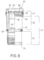
- the cutting sleeve 20 can also be divided into different axial sections structure, as shown in Fig. 6.
- This sealing ring 52 can therefore be referred to as a "thread sealing ring", around it from another sealing ring 50 of the cutting sleeve shown in FIG. 6 20 to distinguish.
- This sealing ring 50 is in one Another radial groove 27, the middle of a thread-free, smooth Sheath section 25 is arranged.
- This radial groove 26 divides the Sheath section 22 in two parts, namely one with an end Cutting edge 24 provided drilling section 23 and one in use cooperating with the aforementioned guide zone 32 of the sleeve 30 Cylinder section 22.
- the cylinder section 22 is larger in diameter formed as the drilling section 23, but goes over a radial shoulder 26 in the threaded portion 21.
- the cutting sleeve 20 is about Height range of their sealing ring 50 closed with a partition 29.
- Fig. 1 shows the cutting sleeve 20 in the left half section before drilling of the plastic tube 40, but already in a middle screw position.
- the plug 16 sits in the mentioned Threaded receptacle 35 of the sleeve 30 and carries a ring seal 17.
- Unscrewed stopper 16 is the one inside the fitting from FIG. 1 located cutting sleeve 20 accessible from above by a tool.
- the turning tool e.g. B. a hex key, engages in a complementary, non-circular plug-in receptacle 18 of the cutting sleeve 20.
- the cutting sleeve becomes 20 unscrewed in the sense of the extension arrow 42.
- the lower end of the drill neck 11 after the injection molding of the housing 10 with a Gate plate 19 is closed is in the initial phase of the tapping process first cut it out and generated it, as shown in FIG. 4, a section 43 in the housing area.
- the final phase of the tapping process then, of course, that which can be seen in the right half section of FIG Drill hole 44.
- A becomes from the wall of the plastic tube 40 Drill core 45 cut out, which then, like the core of the above Cutout 43, into the sleeve interior of the cutting sleeve 20.
- the generated Borehole 44 is thus exactly aligned with that generated by cutout 43 Opening in the housing 10.
- the cutting sleeve 20 is in its full Extended position shown. This is determined by the fact that it has a radial shoulder 26 abuts the aforementioned inner shoulder 36 of the sleeve 30.
- This extension movement 42 of the cutting sleeve 20 is, as already was mentioned, its cylinder portion 22 on the guide zone 32 of the sleeve 30 guided along what can be seen from the intermediate layer shown in Fig. 4 is.
- the sealing ring 50 as shown in FIG. 4, is taken along and runs against the mentioned one before the full extension position of FIG. 5 is shown conical approach 37.
- the approach 37 guides the sealing ring 50 to a special hollow cylindrical end section 60 in the end zone 34 of the sleeve 30. There are namely the following special conditions in front.
- the plastic material 14 also reaches the inside of the sleeve end zone 34 and fills an annular groove 38 provided there or a suitable one other radial recesses. It arises in front of the metallic inner surface the sleeve 40 a plastic skin 61.
- the inner surface of this plastic skin 61 creates the smooth hollow cylindrical end portion 60 which follows "Hollow cylinder section" for short.
- the plastic skin 61 hangs on the foot side, via a bridge 62, with the plastic material 14 of the housing together and is anchored in the annular groove 38 of the sleeve 30.
- the conical approach 37 is minimal; he only needs the top edge to cover the plastic skin 61.
- valve sealing ring 50 It initially serves as a ramp for the valve sealing ring 50. It covers the plastic skin 61 in the axial direction and thereby ensures that the valve sealing ring 50th is lifted onto the cylindrical inner surface 60 of the plastic skin 61. This overlap prevents the cutting sleeve 20 from Plastic skin 61 scrapes or is damaged, which again leads to leaks would lead.
- This plastic-coated hollow cylinder surface 60 is one component the valve sealing point formed here in a special way.
- the other The aforementioned sealing ring 50 is part of this valve sealing point Cutting sleeve 20, which is therefore to be called "valve sealing ring" for short.
- the valve sealing ring presses 50 against the plastic-coated hollow cylinder section 60 of the sleeve and ensures a surprisingly good seal. That in the drilled plastic tube 40 pressurized medium, e.g. B. gas or water do not easily get inside the plastic housing 10.
- the full insertion position of the cutting sleeve 20 is by a locking ring 47 limited, in the present case due to a circumferential thread can be screwed into the mentioned thread receptacle 35 of the sleeve 30.
- This full insertion position of the cutting sleeve 20 is in the left half section indicated by dash-dotted lines in FIG. 1 and in a large magnification in FIG. 8 shown.
- the one mentioned upper sealing ring 51 together with the cutting sleeve 20, with a smooth end piece located above its threaded portion 21 48.
- This sealing ring 51 is referred to below as "sleeve sealing ring" will.
- Threaded sealing ring 52 in the screwing zone 31 of the cutting sleeve 20 has a sealing effect.
- the sleeve sealing ring 51 In its end piece 48
- the cutting sleeve 20 may be tapered or, as in the present case, easily be stepped and have conical transitions between them.
- Fig. 7 shows a modified embodiment 20 'of the above Cutting sleeve of Fig. 6.
- Fig. 6 shows a modified embodiment 20 'of the above Cutting sleeve of Fig. 6.
- Fig. 7 shows a modified embodiment 20 'of the above Cutting sleeve of Fig. 6.
- the main difference is that in its threaded portion 21 two circumferential radial grooves 28 in an axial distance 53 to each other.
- Each of these grooves 28, 28 'each have their own threaded sealing ring 52, 52'. This engage in the internal thread 33 in the manner already described associated sleeve screwing zone 31 of FIG. 1.
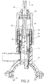
- Fig. 2 is a cap-shaped housing upper part at the upper end of the drill socket 11 55 attached. This attachment can be screwed on and / or Welding are generated. For the latter are electrically heatable Welding elements 54 in the cap inner wall of the upper housing part 55 integrated. Sits in this upper part 55, expediently by application further sealant, a pivot bearing 56 for a shaft 57. This An outer end 58 of the shaft protrudes from the cap 55 where it is be rotated by a turning tool, not shown can.
- the shaft 57 has an inner portion 59 with a non-circular Profile, which is axially displaceable but non-rotatable in a plug adapter 63 intervenes.
- the plug adapter 63 is non-rotatably by means of locking means and up to a certain holding force - also axially fixed in a snap-in fixture 64 of the cutting sleeve 20 at the upper end of the cutting sleeve 20 engaged.
- Locking means 65 is a radially resilient member, for. B. a spring washer.
- For automatically engaging the plug adapter 63 on the cutting sleeve 20 serves an inlet slope 66, which is illustrated in FIG. 6.
- a rotation at the outer end 58 of the shaft thereby has an axial effect Screwing of the sleeve 20 in the housing sleeve 30.
- screwing the adapter 63 is taken away from the cutting sleeve 20 and telescopes along the inner portion 59 of the shaft 57.
Abstract
Description
- Fig. 1
- einen Axialschnitt durch eine Anbohrarmatur nach der Erfindung in einer ersten Verwendungsform, wobei die Schneidbüchse, jeweils im Halbschnitt, in zwei unterschiedlichen Betriebspositionen gezeigt ist,
- Fig. 2
- eine alternative Verwendung der in Fig. 1 gezeigten Armatur mit einem kappenartigen Gehäuseoberteil, der die Armatur drehbetätigbar macht,
- Fig. 3,
- in starker Vergrößerung, ein Detail aus dem Kunststoffgehäuse der Armatur,
- Fig. 4
- in einer der Fig. 3 entsprechenden Darstellung das Kunststoffgehäuse mit einer in diesem Bereich bewegten Schneidbüchse,
- Fig. 5
- die analogen Verhältnisse zu Fig. 4, wenn die Schneidbüchse ihre volle Ausschublage erreicht hat und dadurch eine ventilartige Absperrung in der Armatur erreicht ist,
- Fig. 6,
- in Vergrößerung und im Halbschnitt, die bei der Armatur von Fig. 1 bzw. 2 verwendete Schneidbüchse,
- Fig. 7
- in einer der Fig. 6 entsprechenden Darstellung eine alternative Ausbildung der Schneidbüchse, und
- Fig. 8,
- in Vergrößerung, ein weiteres Detail der in Fig. 1 gezeigten Armatur, wobei sich die Schneidbüchse in voller Einschublage befindet.
- 10
- Kunststoffgehäuse
- 11
- Bohrstutzen
- 12
- Abzweigstutzen
- 13
- Sattel
- 14
- Kunststoffmaterial von 10
- 15
- Schweißelement bei 13
- 16
- Stopfen in 11
- 17
- Dichtung von 16
- 18
- Steckaufnahme in 20
- 19
- Angußplatte bei 11
- 20
- Schneidbüchse
- 20'
- alternative Schneidbüchse (Fig. 7)
- 21
- Gewindeabschnitt von 20
- 22
- Zylinderabschnitt von 20
- 23
- Bohrabschnitt von 20
- 24
- Schneidkante von 23
- 25
- Mantelabschnitt aus 22, 23, Mantelfläche
- 26
- Radialabsatz zwischen 21, 22, Schulter
- 27
- Radialnut in 25
- 28
- Radialnut in 21
- 28'
- weitere Radialnut in 21 (Fig. 7)
- 29
- Trennwand in 20
- 30
- Hülse in 11
- 31
- Schraubzone von 30, Innengewinde-Zone
- 32
- Führungszone von 30
- 33
- Innengewinde von 31
- 34
- Endzone von 30
- 35
- Gewindeaufnahme in 30
- 36
- Innenschulter zwischen 31, 32, Gegenschulter
- 37
- konischer Ansatz vor 34
- 38
- Ringnut in 34
- 39
- Innennut zwischen 35, 31 für 51
- 40
- Kunststoffrohr
- 41
- Anbohrstelle von 40
- 42
- Ausschub-Pfeil, Herausschraubbewegung
- 43
- Ausschnitt in 19 (Fig. 4), Öffnung
- 44
- Bohrloch in 40
- 45
- Bohrkern aus 40
- 46
- Einschub-Pfeil, Einschraubbewegung
- 47
- Sicherungsring, Endanschlag
- 48
- Endstück von 20
- 49
- axialer Abstand zwischen 47, 39 (Fig. 8)
- 50
- Ventildichtring
- 51
- Hülsendichtring
- 52
- Gewindedichtring
- 52'
- weiterer Gewindedichtring (Fig. 7)
- 53
- Axialabstand zwischen 28, 28' (Fig. 7)
- 54
- Schweißelement für 55
- 55
- Gehäuseoberteil, Kappe (Fig. 2)
- 56
- Drehlager in 55 für 57
- 57
- Schaft
- 58
- Außenende von 57
- 59
- unrunder Innenabschnitt von 57
- 60
- Hohlzylinderabschnitt
- 61
- Kunststoffhaut
- 62
- Kunststoffbrücke, Verbindung zwischen 61 und 10
- 63
- Steckadapter (Fig. 2)
- 64
- Schnappaufnahme, Ringnut in 20
- 65
- Rastmittel zwischen 63 und 64, Ringfeder
- 66
- Einlaufschräge an 20 für 65 (Fig. 6)
Claims (19)
- Anbohrarmatur für vorzugsweise unter Mediendruck stehende Kunststoffrohre (40),dadurch gekennzeichnet,mit einem Kunststoffgehäuse (10), das an der anzubohrenden Stelle (41) des Rohres (40) befestigbar ist,wobei das Kunststoffgehäuse (10) einen Bohrstutzen (11) aufweist, an dessen Innenfläche eine Hülse (30) integriert ist,und einen vom Bohrstutzen (11) ausgehenden Abzweigstutzen (12) besizt, der nach dem Anbohren medienführend ist,und mit einer im Bohrstutzen (11) sowohl drehbeweglichen als auch axialbeweglichen Schneidbüchse (20),die in ihrer Ausschublage eine Ventildichtstelle mit dem Bohrstutzen (11) erzeugt und dadurch einen Medienfluß zum Abzweigstutzen (12) absperrt,daß zur Bildung der Ventildichtstelle einerseits die Schneidbüchse (20) einen bei der Dreh- und Axialbewegung mitbeweglichen Ventildichtring (50) trägtund andererseits der Bohrstutzen (11) in einer Endzone (34) der Hülse (30) einen Hohlzylinderabschnitt (60) aufweist,der aus einem mit einer Kunststoffhaut (61) überzogene Bereich (34) der Hülse (30) besteht,daß die Kunststoffhaut (61) aus dem zur Herstellung des Gehäuses (10) dienenden Kunststoffmaterial (14) gebildet istund daß in der Ausschublage der Schneidbüchse (20) der Ventildichtring (50) an der Kunststoffhaut (61) anliegt.
- Anbohrarmatur nach Anspruch 1, dadurch gekennzeichnet, daß die Hülse (30) - in Ausschubrichtung (42) der Schneidbüchse (20) gesehen - vor dem Hohlzylinderabschnitt (60) einen konischen Ansatz (37) besitzt,und daß der konische Ansatz (37) die Kunststoffhaut (61) wenigstens teilweise in axialer Richtung gegenüber dem auflaufenden Ventildichtring (50) überdeckt.
- Anbohrarmatur nach Anspruch 1 oder 2, dadurch gekennzeichnet, daß die untere Endzone (34) der Hülse (30) Radialaussparungen (38) aufweist, in welchen die Kunststoffhaut (61) mit dem zu ihrer Bildung dienenden Kunststoffmaterial (14) verankert ist.
- Anbohrarmatur nach Anspruch 3, dadurch gekennzeichnet, daß die Radialaussparungen aus einer Ringinnennut (38) bestehen.
- Anbohrarmatur nach Anspruch 3 oder 4, dadurch gekennzeichnet, daß die Verankerung der Kunststoffhaut (61) in ihrem die anzubohrende Leitung (40) abgekehrten oberen Bereich erfolgt, während die Kunststoffhaut (61) in ihrem der anzubohrenden Leitung (40) zugekehrten unteren Bereich über eine Kunststoffbrücke (62) mit dem Kunststoffmaterial (14) des Gehäuses (10) verbunden ist.
- Anbohrarmatur nach einem oder mehreren der Ansprüche 1 bis 5, dadurch gekennzeichnet, daß das der anzubohrenden Leitung (40) zugekehrte Unterende des Bohrstutzens (11) zwar zunächst von einer Angußplatte (19) verschlossen ist, aber die Angußplatte (19) in der ersten Phase des Anbohrvorgangs von der Schneidbüchse (20) ausgeschnitten wird, wobei die dadurch im Gehäuse (10) entstehende Öffnung (43) mit dem beim Anbohren erzeugten Bohrloch (44) in der Leitung (40) ausgerichtet ist.
- Anbohrarmatur nach einem oder mehreren der Ansprüche 1 bis 6, dadurch gekennzeichnet, daß die Schneidbüchse (20) eine zylindrische Mantelfläche (25) besitzt, in welcher sich eine Radialnut (27) zur Aufnahme des Ventildichtrings (50) befindet.
- Anbohrarmatur nach einem oder mehreren der Ansprüche 1 bis 7, dadurch gekennzeichnet, daß der Hohlzylinderabschnitt (60) bei der Dreh- und Axialbewegung (42) der Schneidbüchse (20) zu ihrer Führung dient.
- Anbohrarmatur nach einem oder mehreren der Ansprüche 1 bis 8, dadurch gekennzeichnet, daß die Schneidbüchse (20) in wenigstens zwei axiale Abschnitte (21, 25) gegliedert ist, nämlich einen Gewindeabschnitt (21) mit einem Außengewinde und einem glatten Mantelabschnitt (25), dessen Endstück (23) zum Anbohren dientund daß die Hülse (30) mit einem Innengewinde (31) für den Gewindeabschnitt (21) der Schneidbüchse (20) versehen ist und das Innengewinde (31) zum Verschrauben der Schneidbüchse (20) im Bohrstutzen (11) des Kunststoffgehäuses (10) dient.
- Anbohrarmatur nach Anspruch 9, dadurch gekennzeichnet, daß der glatte Mantelabschnitt (25) der Schneidbüchse radial gestuft (22, 23) ist und im Stufenübergang der Ventildichtring (50) sitzt,und daß die Hülse (30) zwischen der den Hohlzylinderabschnitt (60) bildenden Endzone (34) und der das Innengewinde (33) für die Schneidbüchse (20) aufweisenden Schraubzone (31) eine glattwandige Füh(32) für die Schneidbüchse (20) besitzt,und daß der Abzweigstutzen (12) des Kunststoffgehäuses (10) von dieser Führungszone (32) ausgeht.
- Anbohrarmatur nach einem oder mehreren der Ansprüche 1 bis 10, dadurch gekennzeichnet, daß die Schneidbüchse (20) im Bereich ihres Gewindeabschnitts (21) einen weiteren Gewindedichtring (52) trägt, der dichtwirksam in das Innengewinde (33) der Hülse (30) eingreift.
- Anbohrarmatur nach Anspruch 11, dadurch gekennzeichnet, daß die Schneidbüchse (20) wenigstens eine Ringnut (28) zur Aufnahme des Gewindedichtrings (52) aufweist.
- Anbohrarmatur nach einem oder mehreren der Ansprüche 1 bis 12, dadurch gekennzeichnet, daß die Schneidbüchse (20) eine Schulter (26) besitzt, welcher eine Gegenschulter (36) am Übergang zwischen der Innengewinde-Zone (31) und der Führungs-Zone (32) in der Hülse (30) zugeordnet ist.
- Anbohrarmatur nach einem oder mehreren der Ansprüche 1 bis 13, dadurch gekennzeichnet, daß das Innere der Schneidbüchse (20) durch eine Trennwand (29) geschlossen ist und die Trennwand (29) als Sperre für das Druckmedium und/oder den aus dem Kunststoffrohr (40) ausgeschnittenen Bohrkern (45) dient.
- Anbohrarmatur nach einem oder mehreren der Ansprüche 1 bis 14, dadurch gekennzeichnet, daß oberhalb der Innengewinde-Zone (31) der Hülse (30) ein oberer Hülsendichtring (51) angeordnet ist, der in voller Einschraubposition der Schneidbüchse (20) mediendicht an der Schneidbüchse (20) zur Anlage kommt.
- Anbohrarmatur nach Anspruch 15, dadurch gekennzeichnet, daß der Hülsendichtring (51) in einer Innennut (39) der Hülse (30) angeordnet ist, die zwischen der zum Verschrauben der Schneidbüchse (20) dienenden nenden Innengewinde-Zone (31) und einer Gewindeaufnahme (35) für zusätzliche Bauteile (47) in der Hülse (30) andererseits liegt.
- Anbohrarmatur nach Anspruch 16, dadurch gekennzeichnet, daß die Schneidbüchse (20) oberhalb ihres Gewindeabschnitts (21) ein glattwandiges Endstück (48) aufweist, dessen Umfangsfläche in der Einschraubposition am Hülsenring (51) anliegt.
- Anbohrarmatur nach Anspruch 17, dadurch gekennzeichnet, daß die Umfangsfläche des Endstücks (48) sich zur oberen Stirnfläche der Schneidbüchse (20) hin verjüngt.
- Anbohrarmatur nach Anspruch 17 oder 18, dadurch gekennzeichnet, daß in der oberen Gewindeaufnahme (35) der Hülse (30) ein Anschlagring (47) zur Begrenzung der Einschraubbewegung (46) der Schneidbüchse (20) zwar eingeschraubt, aber in seiner Schraubendlage fixiert ist.
Applications Claiming Priority (6)
| Application Number | Priority Date | Filing Date | Title |
|---|---|---|---|
| DE1996130028 DE19630028C2 (de) | 1996-07-25 | 1996-07-25 | Ventilanbohrarmatur für vorzugsweise unter Mediendruck stehende Versorgungsleitungen aus Kunststoff |
| DE19630028 | 1996-07-25 | ||
| DE19705265 | 1997-02-12 | ||
| DE1997105265 DE19705265A1 (de) | 1996-07-25 | 1997-02-12 | Ventilanbohrarmatur für vorzugsweise unter Mediendruck stehende Versorgungsleitungen aus Kunststoff |
| DE19712684 | 1997-03-26 | ||
| DE1997112684 DE19712684A1 (de) | 1997-03-26 | 1997-03-26 | Anbohrarmatur für vorzugsweise unter Mediendruck stehende Kunststoffrohre |
Publications (3)
| Publication Number | Publication Date |
|---|---|
| EP0821193A1 EP0821193A1 (de) | 1998-01-28 |
| EP0821193B1 true EP0821193B1 (de) | 1998-12-16 |
| EP0821193B2 EP0821193B2 (de) | 2005-02-09 |
Family
ID=27216498
Family Applications (1)
| Application Number | Title | Priority Date | Filing Date |
|---|---|---|---|
| EP97109986A Expired - Lifetime EP0821193B2 (de) | 1996-07-25 | 1997-06-19 | Anbohrarmatur für Kunststoffrohre |
Country Status (5)
| Country | Link |
|---|---|
| EP (1) | EP0821193B2 (de) |
| AT (1) | ATE174678T1 (de) |
| DE (1) | DE59700051D1 (de) |
| DK (1) | DK0821193T4 (de) |
| ES (1) | ES2125733T5 (de) |
Families Citing this family (2)
| Publication number | Priority date | Publication date | Assignee | Title |
|---|---|---|---|---|
| DE29806319U1 (de) * | 1998-04-07 | 1999-08-12 | Tillmann Armaturen Gmbh | Anbohrarmatur für Fluidleitungen |
| FR2788582B1 (fr) * | 1999-01-18 | 2001-04-06 | Innovation Generale | Dispositif de branchement d'une canalisation de derivation sur une canalisation de transport de fluide |
Family Cites Families (5)
| Publication number | Priority date | Publication date | Assignee | Title |
|---|---|---|---|---|
| DE4204620A1 (de) † | 1992-02-15 | 1993-08-19 | Manibs Spezialarmaturen | Rohrschelle fuer versorgungsleitungen aus kunststoff, insbesondere anbohrschelle |
| DE4217982C2 (de) * | 1992-05-30 | 1994-06-30 | Friatec Keramik Kunststoff | Ventil-Anbohrarmatur |
| DE4331817C2 (de) * | 1993-09-18 | 1996-05-30 | Puspas Armaturen Gmbh | Anbohrarmatur |
| DE19503888A1 (de) † | 1994-02-08 | 1995-08-24 | Manibs Spezialarmaturen | Schweißfitting mit einem Gehäuse zum Verbinden wenigstens eines Rohrteils |
| DE19531913C2 (de) * | 1994-08-31 | 1999-04-08 | Manibs Spezialarmaturen | Kombinierte Anbohr- und Ventilanbohrarmatur für, insbesondere unter Mediendruck stehende, Versorgungsleitungen aus Kunststoff |
-
1997
- 1997-06-19 DE DE59700051T patent/DE59700051D1/de not_active Expired - Lifetime
- 1997-06-19 AT AT97109986T patent/ATE174678T1/de active
- 1997-06-19 EP EP97109986A patent/EP0821193B2/de not_active Expired - Lifetime
- 1997-06-19 DK DK97109986T patent/DK0821193T4/da active
- 1997-06-19 ES ES97109986T patent/ES2125733T5/es not_active Expired - Lifetime
Also Published As
| Publication number | Publication date |
|---|---|
| DE59700051D1 (de) | 1999-01-28 |
| EP0821193A1 (de) | 1998-01-28 |
| ES2125733T3 (es) | 1999-03-01 |
| DK0821193T4 (da) | 2005-04-11 |
| ES2125733T5 (es) | 2005-08-01 |
| DK0821193T3 (da) | 1999-08-23 |
| ATE174678T1 (de) | 1999-01-15 |
| EP0821193B2 (de) | 2005-02-09 |
Similar Documents
| Publication | Publication Date | Title |
|---|---|---|
| EP1290371B1 (de) | Anbohrarmatur | |
| EP0572817A1 (de) | Anbohrarmatur und Ventil | |
| DE19531913C2 (de) | Kombinierte Anbohr- und Ventilanbohrarmatur für, insbesondere unter Mediendruck stehende, Versorgungsleitungen aus Kunststoff | |
| DE1500162A1 (de) | Absperrhahn | |
| DE4309941C2 (de) | Anbohrarmatur | |
| EP0821193B1 (de) | Anbohrarmatur für Kunststoffrohre | |
| DE4304954C2 (de) | Anbohrschelle mit einer Bohrbüchse | |
| DE19641803C2 (de) | Anbohrarmatur für eine unter Mediendruck stehende Rohrleitung mit einem absperrbaren Ventil | |
| EP3139074A1 (de) | Frostsichere aussenarmatur und verfahren zur montage derselben | |
| EP0811799B1 (de) | Ventil-Anbohrarmatur für vorzugsweise unter Mediendruck stehende Versorgungsleitungen aus Kunststoff | |
| EP0736718A1 (de) | Anbohrarmatur für vorzugsweise unter Mediendruck stehende Versorgungsleitungen aus Kunststoff | |
| EP0931970B1 (de) | Anbohrarmatur mit Absperrfunktion für ein unter Mediendruck stehendes Hauptrohr | |
| DE10021592A1 (de) | Ventilanbohrarmatur für ein insbesondere unter Mediendruck stehendes Rohr | |
| DE19649731C2 (de) | Anbohrarmatur | |
| DE19603254C2 (de) | Ventil-Anbohrarmatur für unter Mediendruck stehende Rohrleitungen | |
| DE19630028C2 (de) | Ventilanbohrarmatur für vorzugsweise unter Mediendruck stehende Versorgungsleitungen aus Kunststoff | |
| DE19630029A1 (de) | Ventilanbohrarmatur für vorzugsweise unter Mediendruck stehende Versorgungsleitungen aus Kunststoff | |
| EP3919789B1 (de) | Sanitärarmatur | |
| DE3704321A1 (de) | Fraeser-anbohrarmatur | |
| DE19801851A1 (de) | Anbohrarmatur für untere Mediendruck stehende Kunststoffrohre | |
| DE19605728A1 (de) | Absperrarmatur für medienführende Leitungen mit einem kugelförmigen Schließkörper im Armaturengehäuse | |
| EP1273836A2 (de) | Ventil | |
| DE4244741C2 (de) | Montagevorrichtung für eine Schutzbuchse zur Vermeidung von Inkrustationen im Bereich einer durch eine Anbohrarmatur hergestellten Bohrung | |
| DE19512591A1 (de) | Anbohrarmatur für insbesondere unter Mediendruck stehende Rohre, wie Gas- oder Wasserrohre | |
| WO1999057479A1 (de) | Anbohrarmatur für unter druck stehende rohrleitungen |
Legal Events
| Date | Code | Title | Description |
|---|---|---|---|
| PUAI | Public reference made under article 153(3) epc to a published international application that has entered the european phase |
Free format text: ORIGINAL CODE: 0009012 |
|
| AK | Designated contracting states |
Kind code of ref document: A1 Designated state(s): AT BE CH DE DK ES FI FR GB GR IE IT LI LU MC NL PT SE |
|
| 17P | Request for examination filed |
Effective date: 19971231 |
|
| GRAG | Despatch of communication of intention to grant |
Free format text: ORIGINAL CODE: EPIDOS AGRA |
|
| GRAG | Despatch of communication of intention to grant |
Free format text: ORIGINAL CODE: EPIDOS AGRA |
|
| GRAH | Despatch of communication of intention to grant a patent |
Free format text: ORIGINAL CODE: EPIDOS IGRA |
|
| 17Q | First examination report despatched |
Effective date: 19980320 |
|
| GRAH | Despatch of communication of intention to grant a patent |
Free format text: ORIGINAL CODE: EPIDOS IGRA |
|
| RBV | Designated contracting states (corrected) |
Designated state(s): AT BE CH DE DK ES FR GB IT LI NL PT SE |
|
| GRAA | (expected) grant |
Free format text: ORIGINAL CODE: 0009210 |
|
| AK | Designated contracting states |
Kind code of ref document: B1 Designated state(s): AT BE CH DE DK ES FR GB IT LI NL PT SE |
|
| REF | Corresponds to: |
Ref document number: 174678 Country of ref document: AT Date of ref document: 19990115 Kind code of ref document: T |
|
| REG | Reference to a national code |
Ref country code: CH Ref legal event code: NV Representative=s name: ISLER & PEDRAZZINI AG Ref country code: CH Ref legal event code: EP |
|
| GBT | Gb: translation of ep patent filed (gb section 77(6)(a)/1977) |
Effective date: 19981221 |
|
| REF | Corresponds to: |
Ref document number: 59700051 Country of ref document: DE Date of ref document: 19990128 |
|
| ET | Fr: translation filed | ||
| REG | Reference to a national code |
Ref country code: ES Ref legal event code: FG2A Ref document number: 2125733 Country of ref document: ES Kind code of ref document: T3 |
|
| REG | Reference to a national code |
Ref country code: PT Ref legal event code: SC4A Free format text: AVAILABILITY OF NATIONAL TRANSLATION Effective date: 19981218 |
|
| PLBQ | Unpublished change to opponent data |
Free format text: ORIGINAL CODE: EPIDOS OPPO |
|
| REG | Reference to a national code |
Ref country code: DK Ref legal event code: T3 |
|
| PLBI | Opposition filed |
Free format text: ORIGINAL CODE: 0009260 |
|
| 26 | Opposition filed |
Opponent name: FRIATEC AKTIENGESELLSCHAFT KERAMIK- UND KUNSTSTOFF Effective date: 19990818 |
|
| PLBF | Reply of patent proprietor to notice(s) of opposition |
Free format text: ORIGINAL CODE: EPIDOS OBSO |
|
| NLR1 | Nl: opposition has been filed with the epo |
Opponent name: FRIATEC AKTIENGESELLSCHAFT KERAMIK- UND KUNSTSTOFF |
|
| PLBF | Reply of patent proprietor to notice(s) of opposition |
Free format text: ORIGINAL CODE: EPIDOS OBSO |
|
| PLAW | Interlocutory decision in opposition |
Free format text: ORIGINAL CODE: EPIDOS IDOP |
|
| APAC | Appeal dossier modified |
Free format text: ORIGINAL CODE: EPIDOS NOAPO |
|
| APAE | Appeal reference modified |
Free format text: ORIGINAL CODE: EPIDOS REFNO |
|
| APAC | Appeal dossier modified |
Free format text: ORIGINAL CODE: EPIDOS NOAPO |
|
| REG | Reference to a national code |
Ref country code: GB Ref legal event code: IF02 |
|
| APBU | Appeal procedure closed |
Free format text: ORIGINAL CODE: EPIDOSNNOA9O |
|
| PUAH | Patent maintained in amended form |
Free format text: ORIGINAL CODE: 0009272 |
|
| STAA | Information on the status of an ep patent application or granted ep patent |
Free format text: STATUS: PATENT MAINTAINED AS AMENDED |
|
| 27A | Patent maintained in amended form |
Effective date: 20050209 |
|
| AK | Designated contracting states |
Kind code of ref document: B2 Designated state(s): AT BE CH DE DK ES FR GB IT LI NL PT SE |
|
| REG | Reference to a national code |
Ref country code: CH Ref legal event code: AEN Free format text: AUFRECHTERHALTUNG DES PATENTES IN GEAENDERTER FORM |
|
| NLR2 | Nl: decision of opposition |
Effective date: 20050209 |
|
| REG | Reference to a national code |
Ref country code: DK Ref legal event code: T4 |
|
| REG | Reference to a national code |
Ref country code: SE Ref legal event code: RPEO |
|
| GBTA | Gb: translation of amended ep patent filed (gb section 77(6)(b)/1977) | ||
| NLR3 | Nl: receipt of modified translations in the netherlands language after an opposition procedure | ||
| REG | Reference to a national code |
Ref country code: ES Ref legal event code: DC2A Date of ref document: 20050506 Kind code of ref document: T5 |
|
| APAH | Appeal reference modified |
Free format text: ORIGINAL CODE: EPIDOSCREFNO |
|
| ET3 | Fr: translation filed ** decision concerning opposition | ||
| REG | Reference to a national code |
Ref country code: CH Ref legal event code: PCAR Free format text: ISLER & PEDRAZZINI AG;POSTFACH 1772;8027 ZUERICH (CH) |
|
| PGFP | Annual fee paid to national office [announced via postgrant information from national office to epo] |
Ref country code: CH Payment date: 20110627 Year of fee payment: 15 Ref country code: SE Payment date: 20110616 Year of fee payment: 15 Ref country code: PT Payment date: 20110524 Year of fee payment: 15 Ref country code: ES Payment date: 20110614 Year of fee payment: 15 |
|
| PGFP | Annual fee paid to national office [announced via postgrant information from national office to epo] |
Ref country code: NL Payment date: 20110628 Year of fee payment: 15 Ref country code: AT Payment date: 20110620 Year of fee payment: 15 Ref country code: DK Payment date: 20110625 Year of fee payment: 15 Ref country code: GB Payment date: 20110616 Year of fee payment: 15 |
|
| PGFP | Annual fee paid to national office [announced via postgrant information from national office to epo] |
Ref country code: BE Payment date: 20110627 Year of fee payment: 15 Ref country code: DE Payment date: 20110420 Year of fee payment: 15 Ref country code: IT Payment date: 20110617 Year of fee payment: 15 |
|
| PGFP | Annual fee paid to national office [announced via postgrant information from national office to epo] |
Ref country code: FR Payment date: 20110711 Year of fee payment: 15 |
|
| REG | Reference to a national code |
Ref country code: PT Ref legal event code: MM4A Free format text: LAPSE DUE TO NON-PAYMENT OF FEES Effective date: 20121219 |
|
| BERE | Be: lapsed |
Owner name: *MANIBS SPEZIALARMATUREN G.M.B.H. & CO. K.G. Effective date: 20120630 |
|
| REG | Reference to a national code |
Ref country code: NL Ref legal event code: V1 Effective date: 20130101 |
|
| REG | Reference to a national code |
Ref country code: DK Ref legal event code: EBP |
|
| REG | Reference to a national code |
Ref country code: SE Ref legal event code: EUG |
|
| REG | Reference to a national code |
Ref country code: CH Ref legal event code: PL |
|
| REG | Reference to a national code |
Ref country code: CH Ref legal event code: PL Ref country code: AT Ref legal event code: MM01 Ref document number: 174678 Country of ref document: AT Kind code of ref document: T Effective date: 20120619 |
|
| GBPC | Gb: european patent ceased through non-payment of renewal fee |
Effective date: 20120619 |
|
| PG25 | Lapsed in a contracting state [announced via postgrant information from national office to epo] |
Ref country code: PT Free format text: LAPSE BECAUSE OF NON-PAYMENT OF DUE FEES Effective date: 20121219 Ref country code: SE Free format text: LAPSE BECAUSE OF NON-PAYMENT OF DUE FEES Effective date: 20120620 Ref country code: IT Free format text: LAPSE BECAUSE OF NON-PAYMENT OF DUE FEES Effective date: 20120619 |
|
| REG | Reference to a national code |
Ref country code: FR Ref legal event code: ST Effective date: 20130228 |
|
| REG | Reference to a national code |
Ref country code: DE Ref legal event code: R119 Ref document number: 59700051 Country of ref document: DE Effective date: 20130101 |
|
| PG25 | Lapsed in a contracting state [announced via postgrant information from national office to epo] |
Ref country code: BE Free format text: LAPSE BECAUSE OF NON-PAYMENT OF DUE FEES Effective date: 20120630 Ref country code: NL Free format text: LAPSE BECAUSE OF NON-PAYMENT OF DUE FEES Effective date: 20130101 Ref country code: LI Free format text: LAPSE BECAUSE OF NON-PAYMENT OF DUE FEES Effective date: 20120630 Ref country code: CH Free format text: LAPSE BECAUSE OF NON-PAYMENT OF DUE FEES Effective date: 20120630 Ref country code: GB Free format text: LAPSE BECAUSE OF NON-PAYMENT OF DUE FEES Effective date: 20120619 Ref country code: DE Free format text: LAPSE BECAUSE OF NON-PAYMENT OF DUE FEES Effective date: 20130101 Ref country code: FR Free format text: LAPSE BECAUSE OF NON-PAYMENT OF DUE FEES Effective date: 20120702 |
|
| PG25 | Lapsed in a contracting state [announced via postgrant information from national office to epo] |
Ref country code: AT Free format text: LAPSE BECAUSE OF NON-PAYMENT OF DUE FEES Effective date: 20120619 |
|
| PG25 | Lapsed in a contracting state [announced via postgrant information from national office to epo] |
Ref country code: DK Free format text: LAPSE BECAUSE OF NON-PAYMENT OF DUE FEES Effective date: 20120702 |
|
| REG | Reference to a national code |
Ref country code: ES Ref legal event code: FD2A Effective date: 20131018 |
|
| PG25 | Lapsed in a contracting state [announced via postgrant information from national office to epo] |
Ref country code: ES Free format text: LAPSE BECAUSE OF NON-PAYMENT OF DUE FEES Effective date: 20120620 |