EP0736718B1 - Anbohrarmatur für vorzugsweise unter Mediendruck stehende Versorgungsleitungen aus Kunststoff - Google Patents
Anbohrarmatur für vorzugsweise unter Mediendruck stehende Versorgungsleitungen aus Kunststoff Download PDFInfo
- Publication number
- EP0736718B1 EP0736718B1 EP96105436A EP96105436A EP0736718B1 EP 0736718 B1 EP0736718 B1 EP 0736718B1 EP 96105436 A EP96105436 A EP 96105436A EP 96105436 A EP96105436 A EP 96105436A EP 0736718 B1 EP0736718 B1 EP 0736718B1
- Authority
- EP
- European Patent Office
- Prior art keywords
- drilling
- drilling device
- valve
- nozzle
- tool
- Prior art date
- Legal status (The legal status is an assumption and is not a legal conclusion. Google has not performed a legal analysis and makes no representation as to the accuracy of the status listed.)
- Expired - Lifetime
Links
- 239000004033 plastic Substances 0.000 title claims description 27
- 238000010079 rubber tapping Methods 0.000 title description 101
- 238000005553 drilling Methods 0.000 claims abstract description 78
- 238000007789 sealing Methods 0.000 claims description 36
- 239000000463 material Substances 0.000 claims description 23
- 230000008878 coupling Effects 0.000 claims description 12
- 238000010168 coupling process Methods 0.000 claims description 12
- 238000005859 coupling reaction Methods 0.000 claims description 12
- 230000000295 complement effect Effects 0.000 claims description 6
- 230000007704 transition Effects 0.000 claims description 6
- 230000001154 acute effect Effects 0.000 claims description 3
- 230000013011 mating Effects 0.000 claims 3
- 238000004512 die casting Methods 0.000 claims 1
- 230000001747 exhibiting effect Effects 0.000 claims 1
- 230000037431 insertion Effects 0.000 claims 1
- 238000003780 insertion Methods 0.000 claims 1
- 230000003014 reinforcing effect Effects 0.000 claims 1
- 238000005520 cutting process Methods 0.000 description 11
- 230000002093 peripheral effect Effects 0.000 description 8
- 238000010438 heat treatment Methods 0.000 description 7
- 230000005540 biological transmission Effects 0.000 description 5
- 229910001369 Brass Inorganic materials 0.000 description 4
- 239000010951 brass Substances 0.000 description 4
- 230000000694 effects Effects 0.000 description 4
- 238000004519 manufacturing process Methods 0.000 description 4
- 244000089486 Phragmites australis subsp australis Species 0.000 description 3
- 238000005452 bending Methods 0.000 description 3
- 238000000034 method Methods 0.000 description 3
- 238000003466 welding Methods 0.000 description 3
- 230000008901 benefit Effects 0.000 description 2
- 239000004020 conductor Substances 0.000 description 2
- 238000013461 design Methods 0.000 description 2
- 230000008569 process Effects 0.000 description 2
- 239000002689 soil Substances 0.000 description 2
- XLYOFNOQVPJJNP-UHFFFAOYSA-N water Substances O XLYOFNOQVPJJNP-UHFFFAOYSA-N 0.000 description 2
- 238000004804 winding Methods 0.000 description 2
- 229910000831 Steel Inorganic materials 0.000 description 1
- 238000004026 adhesive bonding Methods 0.000 description 1
- 238000013459 approach Methods 0.000 description 1
- 230000004888 barrier function Effects 0.000 description 1
- 230000015572 biosynthetic process Effects 0.000 description 1
- 238000006243 chemical reaction Methods 0.000 description 1
- 210000000078 claw Anatomy 0.000 description 1
- 230000007797 corrosion Effects 0.000 description 1
- 238000005260 corrosion Methods 0.000 description 1
- 230000005489 elastic deformation Effects 0.000 description 1
- 238000005485 electric heating Methods 0.000 description 1
- 238000002347 injection Methods 0.000 description 1
- 239000007924 injection Substances 0.000 description 1
- 238000009434 installation Methods 0.000 description 1
- 230000007774 longterm Effects 0.000 description 1
- 239000007769 metal material Substances 0.000 description 1
- PXHVJJICTQNCMI-UHFFFAOYSA-N nickel Substances [Ni] PXHVJJICTQNCMI-UHFFFAOYSA-N 0.000 description 1
- 229910052759 nickel Inorganic materials 0.000 description 1
- 238000003825 pressing Methods 0.000 description 1
- 238000012545 processing Methods 0.000 description 1
- 239000012858 resilient material Substances 0.000 description 1
- 238000007493 shaping process Methods 0.000 description 1
- 239000007787 solid Substances 0.000 description 1
- 239000010959 steel Substances 0.000 description 1
- 238000003860 storage Methods 0.000 description 1
- 239000012815 thermoplastic material Substances 0.000 description 1
- 238000012546 transfer Methods 0.000 description 1
Images


Classifications
-
- F—MECHANICAL ENGINEERING; LIGHTING; HEATING; WEAPONS; BLASTING
- F16—ENGINEERING ELEMENTS AND UNITS; GENERAL MEASURES FOR PRODUCING AND MAINTAINING EFFECTIVE FUNCTIONING OF MACHINES OR INSTALLATIONS; THERMAL INSULATION IN GENERAL
- F16L—PIPES; JOINTS OR FITTINGS FOR PIPES; SUPPORTS FOR PIPES, CABLES OR PROTECTIVE TUBING; MEANS FOR THERMAL INSULATION IN GENERAL
- F16L47/00—Connecting arrangements or other fittings specially adapted to be made of plastics or to be used with pipes made of plastics
- F16L47/26—Connecting arrangements or other fittings specially adapted to be made of plastics or to be used with pipes made of plastics for branching pipes; for joining pipes to walls; Adaptors therefor
- F16L47/34—Tapping pipes, i.e. making connections through walls of pipes while carrying fluids; Fittings therefor
- F16L47/345—Tapping pipes, i.e. making connections through walls of pipes while carrying fluids; Fittings therefor making use of attaching means embracing the pipe
Definitions
- the invention is directed to a tapping fitting in the preamble of claim 1 specified.
- the connection In retrospect is at certain points of pipes carrying gas or water as a medium, the connection a house introduction. To do this, the line must be at this point be drilled, for which tapping fittings are used.
- the known tapping fitting mentioned in the preamble of claim 1 Art has a housing with one for drilling Standpipe and with one for connecting the later house entry serving outlet pipe.
- the housing is in alignment with the standpipe attached to the point of the pipe to be drilled.
- the standpipe has an internal thread in which a cylindrical tapping tool can be screwed is.
- the drilling tool has a receptacle for screwing it for a turning handle, e.g. B. a socket wrench.
- the drilling tool can also take over the function of a valve member because in the area of the lower end of the standpipe a sealing point is arranged with a corresponding counter-sealing point on the drilling tool, if this is screwed into this area of the standpipe by the turning handle has been.
- valve tapping fittings consist of a two-part valve housing consisting of an upper and lower housing, whose lower housing has an internal thread for screwing a cylindrical Has drilling tool.
- the tapping tool is one at the bottom Spindle attached.
- the spindle is both longitudinally displaceable in the upper housing as well as rotatably mounted.
- the tapping tool also forms the valve member.
- the spindle end protruding from the upper housing can also after covering it with soil from the earth's surface are operated, e.g. B. via a key bar to one of the lower housing throttling, closing or reopening the protruding outlet.
- the invention has for its object the effort in the manufacture, Storage and processing of fittings of both types cheaper to design.
- Another object of the invention is to provide a simple, to develop reliably operable tapping fittings that allow precise tapping permitted and is characterized by reliable media sealing. According to the invention, this is achieved by the measures specified in claim 1 achieved, which have the following special meaning.
- the invention uses both for simple tapping fittings and for the more complex valve tapping fittings the same base part, namely the housing of the simple tapping fitting, which is a standpipe and has a discharge pipe.
- a tapping fitting can namely if necessary, the invention is converted at any time into a valve tapping fitting will. This can also be done after the simple one has been set Tapping fitting on the line, done. You need this first a pre-assembled valve cap, which consists of a cap with a axially fixed, externally actuated spindle. If a conversion into a valve tapping fitting is required this cap is only attached to the housing of the tapping valve once to become. You also need an adapter, which is in transition mounted between the simple tapping fitting and the valve attachment becomes.
- the adapter On the side of the valve attachment, the adapter becomes non-rotatable but can be moved lengthways connected to the spindle, which is simply plugged into one another can be done.
- the adapter is on the side of the tapping tool provided with a coupling that is complementary to the mounting in the drilling tool is designed to be complementary and to transmit a torque allowed.
- This support bushing is made of rigid Material, such as brass, which is a plastic case reinforced in this area.
- the position of the cutting tool is through the support bushing in the decisive pipe facing the pipe to be drilled Stabilized area of the drill socket.
- the slidable cutting tool is precisely brought up to the tapping point and throughout Drilling process supported on all sides. It is always for reliable tapping concerned.
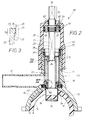
- the valve tapping fitting 90 'shown in FIGS. 1 and 2 comprises a two-part Valve housing 10, 20, namely a housing 10 of one shown in FIG. 6 simple tapping fitting 90, which will be described later, and one of a cap 20 formed upper housing.
- the housing 10 should therefore be the same "Lower housing” are called.
- the lower housing 10 comprises a standpipe 11 with a branch pipe 12 branched from it. Both pipes 11, 12 sit on a clamp part 13 and consist of thermal in one piece weldable plastic.
- the clamp part 13 is over the to be drilled Position 14 of a supply line also made of plastic 15 put on, which leads to pressurized media.
- this valve tapping valve It is 90 'not just this media from line 15 in to direct the outlet pipe 12, for which purpose the tapping at point 14 according to 2 is carried out, but also, during later use, this media inflow, from the outside, throttling like a valve, completely closing off or open again.
- a tapping tool 30 is used, which is in a standpipe 11 provided internal thread 41 can be screwed axially and already 6 is part of the armature 90 of FIG.
- a one-piece, metallic threaded sleeve 40 which is encapsulated by the plastic material of the standpipe 11.
- a sleeve 40 could also be axially inserted into the plastic material push in.
- the appearance is shown in the individual view shown in FIG. 14
- Such a threaded sleeve 40 can be seen, however, opposite the embodiment of FIGS. 1 and 2 is modified.
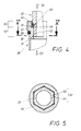
- the threaded sleeve 40 is made of brass and has inside its sleeve that for screwing the tapping tool, which is also made of brass 30 required internal thread 41. Accordingly, the tapping tool comprises a threaded section 31 with an internal thread 41 engaging circumferential thread, as shown in Fig. 4. At her bottom At the end, the threaded sleeve 40 has a valve sealing point 42, with which a valve counter-sealing point 32 provided on the drilling tool 30 cooperates. In the embodiment of FIGS. 1 and 6 there is the sealing point from a valve seat 42 and the counter-sealing point from a valve plate 32 by an oblique shoulder between the circumferential thread portion 31 and a cylindrical cutting knife 34 and an annular seal 33 wears.
- FIG. 15 Another possibility is the sealing point in the standpipe 11 to generate by an elastic O-ring stored there, such as which is shown in Figs. 15 and 16.
- O-ring instead of the O-ring, one could use lip produced from the plastic material of the standpipe 11 can be used. Such interact with the cylindrical surface 33 of the tapping tool 30 Alternatively, O-rings can consist of a lip that is in very inexpensive in one piece from the plastic material of the standpipe 11 is shaped.
- An additional O-ring could also be above one Cross bore 43 of the sleeve 40 may be provided in the upper region of the Standpipe 11 to achieve sealing effects. The cross bore 43 is with aligned the pipe opening of the molded outlet pipe 12.
- a lateral tube extension 44 can also sit in the transverse bore 43, the after overmolding in the plastic material of the tube wall of the standpipe is embedded and for good shaping of the inclined there Outlet pipe 12 is used.
- the axis closes 16 of the standpipe 11 an angle of inclination 18 with the corresponding Axis 17 of the outlet pipe 12 a.
- the outlet pipe 12 instead of in the radial plane recognizable in FIGS. 6 and 1 with respect to the axis the supply line 15, the outlet pipe 12 z. B.
- Threaded sleeve 40 an effective in Fig. 1 inner shoulder 37.
- This snap ring 37 has the task as the upper limit for the one indicated in FIG. 1 by the arrow 35 ' Screwing up the tapping tool 30 to serve.
- the down Directed screw movement is illustrated in Fig. 1 by arrow 35.
- the upper region can be the threaded sleeve 40 still be provided with two further circumferential grooves 29, which are for receiving serve from ring seals 28 recognizable from FIG. 2.
- These ring seals 28 act with the inner surface of the correspondingly profiled standpipe 11 effective together.
- the lower housing 10 enables, as a comparison between FIGS. 1 and 6 shows the double use already mentioned, namely as a valve tapping fitting 90 ', as shown in FIG. 1, or as a simple, immediately above a tapping fitting 90 to be operated from FIG. 6.
- a valve tapping fitting 90 ' as shown in FIG. 1
- the tapping tool 30 a non-circular profiled receptacle 51, in which a rotary handle indicated by dash-dotted lines in FIG. 6 is inserted.
- the turning handle 91 consists of a simple socket wrench, which during a rotation in the sense of the arrow 93 there Tapping tool 30 screwed in the downward direction according to arrow 35.
- 6 is the stop position of the tapping tool 30 illustrated on the inner shoulder 37 when screwing up 35 '.
- a plug 55 as shown in FIG Area of the internal thread 41 located above the inner shoulder 37 the sleeve 40 are screwed.
- a Ring seal 56 can be embedded, the sealing effect on the inner surface of the sleeve becomes.
- the stopper 55 expediently also has an end flange 57, the end 19 of the standpipe 11 or the sleeve end face 46 strikes.
- valve cap 70 When converting the fitting 90 from FIG. 6 into a valve tapping fitting of Fig. 1, only the valve cap 70 is required, which from the formed as a cap 20 upper housing and an axially fixed therein rotatably Spindle 21 exists.
- a bearing ring 64 is used, which is made of plastic material the cap 20 is molded around.
- two ring seals 66 arranged with the inner surface the cap 20 are effective sealing.
- the valve cap 70 is pre-assembled.
- an adapter 22 required as a connector between the spindle 21 and the Tapping tool 30 is used.
- the adapter 22 is non-rotatable, but is longitudinally displaceable connectable to the spindle 21 and has at its lower End of a complementary to the above-mentioned receptacle 51 in the tapping tool 30 Coupling 52, which is releasable and a torque transmitting Connection 50, as shown in FIG. 4, generated.
- Coupling 52 which is releasable and a torque transmitting Connection 50, as shown in FIG. 4, generated.
- the spindle 21 consists of a solid shaft.
- the adapter 22 is formed as a sleeve that covers the spindle 21 in some areas.
- the In the present case, shaft profile 23 is a square and the bush cross section 24 a square opening.
- the spindle 21 protrudes with an end piece 71 from an axial bore the cover of the cap 20 out and can be there from an elastic sealing sleeve 69 be enclosed.
- the end piece 71 has a non-round profiled engagement surface 72 for a turning tool which has a turning operation in the sense of arrows 58, 58 'of FIG. 1.
- the tapping tool 30 moves in the unscrewing direction 35 of Fig. 1 down, the adapter 22 axially from the spindle 21 extends until it finally reaches the end position shown in FIG. 2 is. As already mentioned, this is done by pressing the tool side Valve plates 32 marked on the housing-side valve seat 42.
- valve 90 ' When the valve 90 'is actuated for the first time, it is cut out of the drill core 14 'shown in FIG. 2 from the supply line 15 instead of.
- the result By means of a corresponding declining rotary actuation 58 ′ from FIG. 1 the result is one marked by the aforementioned arrow 35 'of FIG. 1 Screw-up movement of the tapping tool 30.
- the Valve plate 32 increasingly removed from valve seat 42 and thus a growing one Passage for the medium from the supply line 15 in the Branch pipe 12 allows.
- the valve cap 70 with the adapter 22 is not only easy and quickly with the tapping tool located in the valve lower housing 10 30 clutch, but also hold reliably in clutch engagement because, as can be seen in FIGS. 4 and 5, there is also a snap lock 60 is provided.
- the connection 50 described lies in this case in axial offset to the snap lock 60.
- the adapter socket 22 at its lower end a coupling 52 which, according to the cross-sectional view of Fig. 5, consists of a hexagon.
- the adapter 22 is with its coupling 52 in the aforementioned recording 51 inserted, which sunk inside the tubular drilling tool 30 is arranged.
- the receptacle 51 consists of a hexagon hole.
- the two closing halves 61, 62 of the snap lock 60 mentioned are axially higher than the connection 50.
- the present Case consists of the closing half provided in the tapping tool 30 a radially undercut recess 61, while the complementary other closing half is formed from a spring ring 62, which in a circumferential groove 63 of the adapter socket 22 is embedded.
- Both the Connecting parts 51, 52 and the two closing halves 61, 62 are by an axial plug-in movement in the sense of that shown in FIG. 4 Arrow 53 can be brought into engagement with one another, namely the two snap Locking halves 61, 62 only interlock when the full engagement position of the two coupling halves 51, 52 is present.
- the adapter 22 advantageously consists of corrosion-resistant material, which is particularly suitable Chrome-nickel steel according to DIN 47237 have proven. This material also serves to form the snap ring 37.
- the invention uses the knowledge that the rotary driving surfaces are only in the narrowed socket end piece 25 are located, while the shaft 21 acts with changing axial zones. That's why the shaft profile 23 of the spindle 21 is rigid, but the non-circular Socket cross section 24 designed in some areas to be resilient.
- two are used for this from resilient Material existing plates 81, with their respective plate ends 82 in two longitudinal grooves 75 inside the opening cross section 24 of the Adapter socket 22 are embedded.
- the inner surface of the spring plate 81 does not yet form the effective rotary driving surface 84 for that in FIG inserted shaft profile.
- the two neighboring areas in the Opening cross section 24 are cut out at 24 and are not used Rotary driving.
- the other two edges of the Shafts 21 can in the above-mentioned cuts 74 of the adjacent Retract cross-sectional areas.
- the upper limit for torque transmission, when exceeded, the overload lock 80 takes effect, can by selecting the spring material of the plates 81, their Determine the plate thickness and its clamping depth in the longitudinal grooves 75.
- valve lower housing 10 When using the valve lower housing 10 as a simple tapping fitting 90, according to FIG. 7, it is possible to use in addition to that described Stopper 55, also an end cap 77 on the upper end piece 78 to fix the standpipe 11.
- the attachment between the end cap 77 and the standpipe 11 is expediently carried out by the closer welding to be explained, but other fastening methods, such as gluing or threaded connections. Conveniently these parts are attached in the same way as the cap 20 of the valve cap 70 when converting the tapping fitting 90 into the valve tapping fitting 90 '.
- This valve cap 70 too is, as explained in FIG. 2, on the same upper end piece 78 of the standpipe 11 attached and connected.
- Heating wires 85 which can be seen in FIG. 2, are used for this purpose the inner surface of the cap 20 or the end cap shown in FIG. 7 77 and on the inner contact surface 79 of the clamp part described 13 are arranged according to FIG. 2. The same can also be done for the connection a further pipe at the end of the outlet pipe 12 apply.
- Appropriately used for the installation of the heating wire in these plastic parts each take up the winding of the heating wire 85, 9 apparent bobbin 86 or a support plate 87, the receiving grooves arranged according to the desired wire course exhibit.
- the coil formers equipped with the heating wire 85 86, 87 are inserted into the injection mold, in which the complete Plastic parts 10, 20, 77 are injected.
- the carrier plate 87 is integrated into the clamp part 13 and encloses, as from the dashed 9 indicated plate limitation can be seen, saddle-shaped the lower opening of the standpipe 11.
- the ones equipped with the heating wire 85 Parts 10, 20, 77 are connected to electrical connections 88, which can be seen from FIGS. 7 and 10.
- the invention Before a final welding attachment of the clamp part 13 to the peripheral surface the supply line 15 and when drilling is a temporary Attachment of the valve lower housing 10 at the desired tapping point required.
- the invention opens up different, optional usable possibilities.
- One is to have a bell counterpart use which with screw or clamp connections with the Housing 10 belonging clamp part 13 is mechanically connected.
- the housing 10 preferably has in pairs on each Side arranged radial lugs 92, which through holes 89 for have appropriate fasteners.
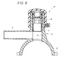
- Fig. 8 shows a variant 10 'of the housing as a simple application Tapping fitting 90 ", which is compared to the previously described Sub-housing 10 differs only in that the preceding always used metallic threaded sleeve 40 is omitted and for screwing of the tool 30 serving internal thread 41 directly in the inner surface of the standpipe 10 are arranged. In all other respects the applies previous description.
- This version 10 ' is preferred for small ones Pipe diameters used, which are under moderate pressure and z. B. lead gas. In this case, the drilling forces are proportional low. But if there are large pipe diameters and accordingly thick-walled pipes have to be drilled, one uses the above-described tapping fitting 90, the housing 10, the threaded sleeve 40 has.
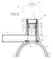
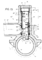
- nozzle 15 consists of a one-piece housing 10 "made of plastic, which consists of a vertical drill socket 20 ' in the angled branch pipe 12 'and one for attachment the housing 10 "on a pipe 15 to be drilled serving saddle 13 'exists.
- the dash-dotted nozzle axes 16, 17 run the two connecting pieces 12 ', 20' in the embodiment of Fig. 15 perpendicular to each other.
- the branch pipe 12 ' opens out opposite one its nozzle cross section narrowed opening 43 in the drill neck 20 'a. This opening is hereinafter referred to as "mouth opening 43" will.
- the saddle 13 'of the housing 10 is used to attach the valve to a desired location 14 on an existing of thermoplastic material Attach pipe 15.
- the pipe 15 can under higher media pressure stand, where gas, water or the like can serve as media.
- the fastening acts with the saddle 13 ', which is indicated by dash-dotted lines in FIG. 15 Clamp 13 or the like.
- the crucial attachment by a welded connection using an electric heating coil in the Area of the indicated contact surfaces 79 between the saddle 13 ' and the peripheral surface of the tube 15 comes about, the heat conductor 85 is shown in cross section in FIG.
- the drill pipe 20 After its attachment runs the drill pipe 20 'vertically, while the branch pipe 12' thereof horizontally protrudes.
- Both nozzle axes 16, 17 lie in one plane, which the cross-sectional plane of the drawing of FIG. 15 is determined.
- the drill socket 20 ' has a special in the present case formed internal thread 41, in which the tapping tool 30 can be screwed is.
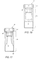
- This tapping tool 30 comprises one with a corresponding one External thread 31 provided head piece 3o ', which is a cylindrical Connects shaft piece 21 with a smooth peripheral surface 21 '.
- the drilling tool 30 is sleeve-shaped and the outer diameter of the Shank piece 21 set off from that of the head piece 20 '.
- a non-circular Area 51 which in the present case is designed as a hexagon socket and for inserting a corresponding counter profile Actuating tool is used.
- This operating tool e.g. B. an Allen key, serves to move the tapping tool 30 from the upper end position, which is shown in Fig.
- the tool 30 cuts a wall area from the tube 15 out, which stand as a drill core 14 'in the interior of the shaft piece 21 remains and closes the cross-section there in a media-tight manner.
- a support bush 100 is arranged whose inside diameter is the diameter of the circumferential surface 34 " is precisely adapted by the tapping tool 30 and therefore for its sliding guidance serves. Already protrudes in the above, retracted position the tapping tool 30 into the upper region of the support bush 100.
- an upper ring seat 101 which is used to hold a upper sealing ring 102 is used.
- a Cutting edge 34 ' Provided shaft end precisely against the end to be drilled Introduced point 14 in the pipe 15
- the support bush 100 has a lower ring receptacle 103, in which an annular lip seal 104 is arranged. The two seals 102, 104 close the aforementioned opening 43 between them of the branch pipe 12 '.
- Threaded sleeve 40 which is formed from dimensionally stable material.
- This dimensionally stable Material could be a harder plastic, but this will Case metallic material, namely in particular brass, used.
- This threaded sleeve 40 is at an axial distance 107 from that in the lower Area of the drill socket 20 'in the plastic bushing support bush 100 located away. 19 and 20 show, but can the threaded sleeve 40 and the support bush 100 are also formed in one piece be.
- This distance 107 flows when the housing is die-cast 10 "the plastic material and forms a socket 100 of the Sleeve 40 separating web 108 made of plastic material.
- the clear expanse 105 of the support bush 100 is smaller than the inner width 109 of the with Internal thread 41 equipped portion of the threaded sleeve 40 is formed.
- the threaded sleeve 40 is in its upper region with a step 40 ' provided that has a larger clear width with an internal thread, in which an end plug, not shown, can be screwed in.
- a snap ring 37 or the like which acts as an upper stop serves when screwing the tapping tool 30 up and therefore its mentioned upper, retracted position limited.
- the snap ring 37 is positioned in an inner groove embedded in the widened end section 40 '.
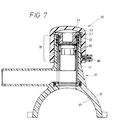
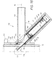
- FIG. 16 shows a modified version of the tapping fitting, to which, in addition to the drilling tool 30 already described, one opposite 15 modified housing 110 is used.
- this housing 110 comprises a drill socket 111 and one over a Mouth opening 114 branch branch 112 extending therefrom and a for fastening the housing 110 to the saddle 113 serving the pipe 15, but these housing parts are both to each other and in terms of to be drilled pipe 15 positioned differently.
- here too dashed lines indicated two nozzle axes 16, 17 run these 117 at an acute angle and lie after attachment of the housing 110, essentially in a direction passing through the tube axis 118 Axial plane, which is the drawing plane of Fig. 16. It is a V housing 110 before.
- the tapping tool 30 is in the introduced and inclined to the pipe axis 118 extending drill pipe 111 performed the drilling work in the manner described. It is important that also the one decisive for the flow path of the medium after drilling Branch pipe 112 lies horizontally and therefore on the branch pipe 112 further pipe to be attached at the same level as the pipe 15 can continue to run.
- the diameter of both nozzles 111, 112 is in the Usually considerably smaller than the outer diameter of the tube 15.
- the branch pipe 112 runs perpendicular to the pipe axis 118.
- the drill socket 111 runs with a longitudinal oval Inner opening 115 in the saddle 113.
- the attachment also takes place here of the V housing 110 by welding. 16 are the windings for this purpose an electrical heating conductor integrated in the area of the contact surface 85 indicated in cross section, one connection point in the area of a attached contact block 119 can be seen. Because the drilling process in the sense of the drill socket axis 17 inclined in the wall of the pipe 15 a longitudinal oval wall cutout is created there.
- the components described in the first embodiment of FIG. 15, namely the support sleeve 100 and the threaded sleeve 40 "for the formation of the internal thread 41 are also here in the manner already described realized. In this respect, the previous description applies.
- the support bush 100 extends to the plant with the peripheral surface of the to be drilled Rohres 15.
- the outer sealing ring 102 is the Inner opening 115 pointing inner sealing ring 116 not in a radial plane to the drill socket axis 17, but inclined. This inner sealing ring 116 runs in a plane parallel to the pipe axis 118.
- the support bushing 100 of FIG. 16 has the desired position of the two Sealing rings 102, 116 inclined ring receptacles 101, 126.
- the a sealing ring 116 can also be designed as a lip seal.
- Fig. 20 is the outer surface of the threaded sleeve shown in Fig. 19 40 recognizable. This comprises two opposing thread grooves 121, 122, which prevent the aforementioned violent distortion from happening the threaded sleeve 40 anchored in the plastic of the fitting also rotates.
- the transverse bore 43 ' is rectangular in this threaded bushing 40 Breakout formed in the section defining the support bushing 100 '.
- the releasable coupling explained in FIG. 4 is advantageous is designed as a snap coupling, which is a lightweight one axial coupling between the tapping tool 30 and the adapter 22 allows, the two parts 30, 22 but not again easily uncoupling allowed.
- This can be done simply by: the recess 61 described in FIG. 4 provides a steep flank and not with the conical transition. To engage this securely to ensure, one will also act as the other closing half Spring ring 62 not with a round cross section, but with a rectangular cross section Mistake. This rectangular cross section is based on the steep Cross from 61.
Landscapes
- Engineering & Computer Science (AREA)
- General Engineering & Computer Science (AREA)
- Mechanical Engineering (AREA)
- Branch Pipes, Bends, And The Like (AREA)
- Perforating, Stamping-Out Or Severing By Means Other Than Cutting (AREA)
Description
- Fig. 1
- einen Axialschnitt durch eine komplette Ventil-Anbohrarmatur nach der Erfindung, die an einer noch anzubohrenden Versorgungsleitung angebracht ist, wobei die Schnittführung in einer Querschnittsebene der Leitung liegt,
- Fig. 2
- die in Fig. 1 gezeigte Ventil-Anbohrarmatur nach Vollzug des Anbohrens der Versorgungsleitung, wobei eine Absperrfunktion an der Bohrstelle sich ergibt,
- Fig. 3
- in Vergrößerung ein in Fig. 2 mit III gekennzeichnetes Detail der Armatur,
- Fig. 4
- in Vergrößerung ein in Fig. 2 mit IV gekennzeichnetes Detail der Armatur,
- Fig. 5
- in Vergrößerung einen kompletten Horizontalschnitt durch die in Fig. 4 gezeigten inneren Bauteile längs der dort angedeuteten Schnittlinie V,
- Fig. 6,
- ebenfalls im Axialschnitt, eine mit dem Ventil-Untergehäuse von Fig. 1 erzeugte einfache Anbohrarmatur mit einer strichpunktierten Drehhandhabe in einer der Fig. 1 entsprechenden Schnittführung,
- Fig. 7
- die in Fig. 4 gezeigte Anbohrarmatur mit eingesetzten Stopfen, nachdem diese ergänzend noch mit einer Endkappe versehen worden ist,
- Fig. 8
- in einer Fig. 7 entsprechenden Darstellung eine alternative Ausbildung der Anbohrarmatur,
- Fig. 9
- eine weitere alternative Gestaltung einer Anbohrarmatur, zwar auch im Axialschnitt, aber die Schnittführung in einer zu Fig. 6 senkrechten Ebene, nämlich längsparallel zu einer dort nicht mitgezeichneten Versorgungsleitung, liegt,
- Fig. 10
- eine Draufsicht auf die Anbohrarmatur von Fig. 1 mit angeformtem Schellenteil,
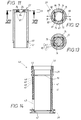
- Fig. 11
- in Vergrößerung einen Längsschnitt durch eine alternative Ausgestaltung eines bereits in Fig. 1 gezeigten Adapters der Ventil-Anbohrarmatur,
- Fig. 12
- einen Querschnitt durch den Adapter von Fig. 11 längs der dortigen Schnittlinie XII-XII,
- Fig. 13
- den in Fig. 12 gezeigten Querschnitt, worin die dort erzielbare Wirkung einer Drehüberlastsperre erläutert ist,
- Fig. 14
- einen Längsschnitt durch eine alternative Ausgestaltung eines metallischen Einsatzes im Gehäuse der Anbohrarmatur,
- Fig. 15
- einen Querschnitt durch das anzubohrende Rohr mit einer daran angebrachten Anbohrarmatur einer ersten Ausführung in einem in der gleichen Ebene liegenden Längsschnitt des Gehäuses, wo das Schneidwerkzeug, jeweils im Halbschnitt gesehen, in zwei unterschiedlichen Positionen dargestellt ist,
- Fig. 16
- einen horizontalen Axialschnitt durch ein Teilstück eines anzubohrenden Rohres mit einer daran befestigten Anbohrarmatur, deren Gehäuse in der gleichen Ebene geschnitten ist und das Schneidwerkzeug, jeweils im Halbschnitt dargestellt, in zwei unterschiedlichen Positionen zeigt,
- Fig. 17 und 18
- Längsschnitte durch das Anbohrwerkzeug in zwei alternativen Ausführungen,
- Fig. 19
- einen der Fig. 14 entsprechenden Längsschnitt durch den metallischen Einsatz im Gehäuse und
- Fig. 20
- die Draufsicht auf den in Fig. 19 gezeigten metallischen Einsatz.
- 10
- Gehäuse, Ventil-Untergehäuse
- 10'
- vereinfachte Variante von 10 (Fig. 8)
- 10"
- einstückiges Gehäuse
- 11
- Standrohr von 10
- 12
- Abgangsrohr von 10
- 12'
- Abzweigstutzen
- 13
- Schellenteil von 10
- 13'
- Sattel von 10"
- 14
- Anbohrstelle an 15
- 15
- ausgeschnittener Bohrkern von 15
- 16
- Versorgungsleitung, Leitung
- 17
- Achse des Standrohres 11, Stutzenachse
- 18
- Achse des Abgangsrohres 12, Stutzenachse
- 19
- Neigungswinkel zwischen 16, 17 (Fig. 9)
- 20
- oberes Stirnende von 11
- 20'
- Ventil-Obergehäuse, Kappe
- 21
- vertikaler Bohrstutzen
- 21'
- Spindel, Schaft
- 21"
- Umfangsfläche von 21
- 22
- Verkantungslage von 21 im Überlastfall (Fig. 13)
- 23
- Adapter, Buchse
- 24
- Schaftprofil von 21
- 25
- Öffnungsquerschnitt der Buchse 22
- 26
- verengtes Buchsen-Endstück von 22
- 27
- endseitige Radialverbreiterung von 21 (Fig. 3)
- 28
- freier Spalt zwischen 21, 22 (Fig. 1)
- 29
- Ringdichtung bei 40
- 30
- Umfangsnut für 28 (Fig. 14)
- 30
- Anbohrwerkzeug, Schneidwerkzeug
- 30'
- Kopfstück von 30
- 31
- Umfangsgewindeabschnitt, Außengewinde von 30
- 32
- Ventil-Gegendichtstelle, Ventilteller an 30
- 33
- Ringdichtung bei 32
- 34
- zylindrische Umfangsfläche, Schneidmesser von 30
- 34'
- Schneidkante von 34
- 34"
- Umfangsfläche von 30
- 35
- abwärts gerichtete Schraubbewegung von 30
- 35'
- aufwärts gerichtete Schraubbewegung von 30
- 36
- Innennut in 40 (Fig. 14)
- 37
- Innenschulter in 40, Sprengring
- 38
- elastischer Dichtring in 39
- 39
- Umfangsnut von 40 bei 42
- 40
- Gewindehülse
- 40'
- äußerer Endabschnitt von 40
- 40"
- Gewindehülse (Fig. 16)
- 41
- Innengewinde von 40
- 42
- Ventil-Dichtstelle, Ventilsitz in 11
- 43
- Querbohrung in 40 (Fig. 14), Mündungsöffnung (Fig. 15)
- 43'
- Querbohrung (Fig. 19/20)
- 44
- metallischer Rohransatz bei 43 (Fig. 9)
- 45
- Zentrierbohrung an 40 (Fig. 14)
- 46
- Hülsen-Stirnfläche von 40
- 47
- Umfangs-Längsprofil von 40
- 48
- linksgängiges Umfangsgewinde für 47
- 49
- rechtsgängiges Umfangsgewinde für 47
- 50
- ein Drehmoment übertragende Verbindung zwischen 51, 52
- 51
- Aufnahme, Innensechskant in 30
- 52
- Kupplung in 22
- 53
- Steckbewegungs-Pfeil zwischen 22, 30 (Fig. 4)
- 53'
- Auszugsbewegungs-Pfeil zwischen 22, 30 (Fig. 4)
- 54
- Bohrloch in 15 (Fig. 2)
- 55
- Stopfen (Fig. 7)
- 56
- Ringdichtung von 55 (Fig. 7)
- 57
- Endflansch an 55
- 58
- Drehbetätigungs-Pfeil von 71 (Fig. 1)
- 58'
- Gegen-Drehbetätigungs-Pfeil von 71 (Fig. 1)
- 59
- Umfangsschulter an 22 (Fig. 4)
- 60
- Schnappverschluß
- 61
- erste Schließhälfte von 60, hinterschnittene Ausnehmung in 30
- 62
- andere Schließhälfte von 60, Federring (Fig. 4)
- 63
- Umfangsnut für 62 (Fig. 4)
- 64
- Lagerring für 21 (Fig. 1)
- 65
- Ringdichtung in 21 (Fig. 2)
- 66
- Ringdichtung in 64 (Fig. 2)
- 67
- Ringinnenfläche von 64 (Fig. 2)
- 68
- Ringumfangsfläche von 64 (Fig. 2)
- 69
- Dichtungsmanschette (Fig. 2)
- 70
- Ventilaufsatz (Fig. 1)
- 71
- herausragendes Spindelende von 21
- 72
- Werkzeug-Angriffsfläche an 71
- 73
- Übertragungsbereich für Drehmomente zwischen 21, 22 (Fig. 3)
- 74
- freigeschnittene Nachbarfläche von 84, Freischnitt
- 75
- Längsnut für 82 (Fig. 12)
- 76
- Radialausnehmung hinter 81 (Fig. 12)
- 77
- Endkappe (Fig. 7)
- 78
- oberes Endstück von 11 (Fig. 2, 7)
- 79
- Anlagefläche an 13 für 15 (Fig. 2)
- 80
- Überlastsperre (Fig. 13)
- 81
- Federplatte für 80
- 81'
- Biegeposition von 81 (Fig. 13)
- 82
- Plattenende von 80
- 83
- Biegepfeil von 81 (Fig. 12)
- 84
- wirksame Drehmitnahmefläche von 24 (Fig. 12)
- 85
- Heizdraht
- 86
- Spulenkörper von 85 (Fig. 9)
- 87
- Trägerplatte für 85 (Fig. 9)
- 88
- elektrische Anschlüsse für 85 (Fig. 7, 10)
- 89
- Durchtrittsloch an 92 (Fig. 10)
- 90
- Anbohrarmatur (Fig. 6, 7)
- 90'
- Ventil-Anbohrarmatur (Fig. 1, 2)
- 90"
- abgewandelte Anbohrarmatur (Fig. 9)
- 90"'
- alternative Anbohrarmatur (Fig. 9)
- 91
- Drehhandhabe für 30 (Fig. 6)
- 92
- Radialansatz (Fig. 1, 8, 10)
- 93
- Drehpfeil für 91 (Fig. 6)
- 94
- konische Verjüngung
- 95
- Innenwand
- 96
- Schulter in 30
- 97
- Gegenschulter
- 98
- Nut
- 99
- Nut
- 100
- Stützbuchse (Fig. 15)
- 100'
- Stützbuchse (Fig. 15)1
- 101
- obere / äußere Ringaufnahme in 100
- 102
- oberer / äußerer Dichtring
- 103
- untere Ringaufnahme in 100
- 104
- untere Lippendichtung
- 105
- lichte Weite von 100
- 106
- Innenöffnung von 20'
- 107
- Axialabstand zwischen 40 und 100
- 108
- Steg aus Kunststoffmaterial bei 107
- 109
- Innenweite von 40
- 110
- V-Gehäuse (Fig. 16)
- 111
- Bohrstutzen von 110
- 112
- Abzweigstutzen von 110
- 113
- Sattel von 110
- 114
- Mündungsöffnung von 112
- 115
- Innenöffnung von 111
- 116
- innerer Dichtring (Fig. 16)
- 117
- spitzer Winkel von 16, 17 (Fig. 16)
- 118
- Rohrachse von 111
- 119
- Kontaktanschlußblock von 88
- 120
- Ringaufnahme in 100 für 116
- 121
- Gewindenut (Fig. 20)
- 122
- Gewindenut (Fig. 20)
- 123
- längsovaler Wandausschnitt in 15
- 124
- Innenöffnung von 16
- 125
- äußerer Endabschnitt von 40"
- 126
- Achse von 15
Claims (26)
- Anbohrarmatur (90) für vorzugsweise unter Mediendruck stehende Versorgungsleitungen (15) aus Kunststoff,dadurch gekennzeichnet,mit einem über der anzubohrenden Stelle (14) der (11) Leitung (15) zu positionierenden Gehäuse (10) mit einem Standrohr (11) und mit einem Abgangsrohr (12),wobei das Standrohr mit einem Innengewinde (41) versehen ist und im Bereich seines der Leitung zugekehrten Unterendes eine Ventil-Dichtstelle (42) aufweist,und mit einem im Innengewinde (41) des Standrohres (11) verschraubbaren, zylindrischen Anbohrwerkzeug (30), welches eine Aufnahme (51) für eine Drehhandhabe (91) und eine Ventil-Gegendichtstelle (32) besitzt,daß der Anbohrarmatur (90) einerseits ein vormontierter Ventilaufsatz (70) zugeordnet ist,bestehend aus einer Kappe (20) mit einer darin axialfest drehgelagerten (64), von außen drehbetätigbaren (58, 58') Spindel (21),wobei die Kappe (20) als Obergehäuse an dem als Untergehäuse fungierenden Gehäuse (10) der Anbohrarmatur (90) befestigbar ist und diese in eine Ventil-Anbohrarmatur (90') mit einem aus dem Unter- und Obergehäuse (10, 20) gebildeten Ventilgehäuse wandelt,und daß der Anbohrarmatur (90) und dem Ventilaufsatz (70) andererseits ein Adapter (22) zugeordnet ist,der zwar drehfest aber längsverschieblich mit der Spindel (21) des Ventilaufsatzes (70) zusammengesteckt ist und eine zu einer Aufnahme (51) im Anbohrwerkzeug (30) komplementäre, lösbare, ein Drehmoment übertragende Kupplung (52) besitzt.
- Anbohrarmatur nach Anspruch 1, dadurch gekennzeichnet, daß der Adapter (22) einerseits und das Anbohrwerkzeug (30) andererseits die beiden komplementären Schließhälften (61, 62) eines Schnappverschlusses (60) besitzt, (Fig. 4).
- Anbohrarmatur nach Anspruch 1 und 2, dadurch gekennzeichnet, daß sowohl die Kupplung (52) vom Adapter (22) und die Aufnahme (51) vom Anbohrwerkzeug (30) als auch die beiden Schließhälften (61, 62) des Schnappverschlusses (60) durch eine axiale Steckbewegung (53) in Eingriff bringbar und durch eine axiale Auszugsbewegung (53') voneinander lösbar sind, (Fig. 4).
- Anbohrarmatur nach einem oder mehreren der Ansprüche 1 bis 3, dadurch gekennzeichnet, daß zwischen der Spindel (21) und dem Adapter (22) Endanschläge (25, 26) angeordnet sind, die den maximalen Axialausschub begrenzen, und der Adapter (22) mit dem Ventilaufsatz (70) eine unverlierbare vormontierte Baueinheit bildet, (Fig. 3).
- Anbohrarmatur nach einem oder mehreren der Ansprüche 1 bis 4, dadurch gekennzeichnet, daß das Unter- und Obergehäuse (10, 20) der Ventil-Anbohr-Anbohrarmatur, wie das Standrohr (11), das Abgangsrohr (12), die Kappe (20) und ein das Standrohr (11) tragender, an der anzubohrenden Leitung befestigbarer Schellenteil (13), aus Kunststoffmaterial bestehen.
- Anbohrarmatur nach einem oder mehreren der Ansprüche 1 bis 5, dadurch gekennzeichnet, daß die Ventil-Dichtstelle (42) im Standrohr (11) aus einem Ventilsitz und die Ventil-Gegendichtstelle (32) am Anbohrwerkzeug (30) aus einem Ventilteller bestehen, (Fig. 6).
- Anbohrarmatur nach einem oder mehreren der Ansprüche 1 bis 5, dadurch gekennzeichnet, daß die Ventil-Dichtstelle (42) aus mindestens einem im Standrohr (11) gelagerten, elastischen O-Ring und die Ventil-Gegendichtstelle (32) von der zylinderischen Umfangsfläche (34) des Anbohrwerkzeugs (30) gebildet sind.
- Anbohrarmatur nach Anspruch 7, dadurch gekennzeichnet, daß der O-Ring aus einer einstückig aus dem Kunststoffmaterial des Standrohres (11) erzeugten Lippe besteht.
- Anbohrarmatur nach einem oder mehreren der Ansprüche 1 bis 8, dadurch gekennzeichnet, daß die Spindel aus einem Schaft (21) mit unrundem Schaftprofil (23) und der Adapter aus einer die Spindel ummantelnden Buchse (22) mit unrundem Öffnungsquerschnitt (24) bestehend (Fig. 3).
- Anbohrarmatur nach einem oder mehreren der Ansprüche 1 bis 9, dadurch gekennzeichnet, daß wenigstens eine der Drehmitnahmeflächen (84) zwischen der Spindel (21) und dem Adapter (22) elastisch nachgiebig (81') ausgebildet ist und eine Drehüberlastsperre (80) bilden (Fig. 11 bis 13).
- Anbohrarmatur nach Anspruch 10, dadurch gekennzeichnet, daß die Überlastsperre (80) aus wenigstens einer elastisch biegsamen Federplatte (81) besteht, deren beide Plattenenden (82) im Inneren des Öffnungsquerschnitts (24) des Adapters (22) aufgenommen sind,während der Schaft einen starren Schaftquerschnitt aufweist,und der Öffnungsquerschnitt (24) des Adapters (22) auf der von der Spindel (21) abgekehrten Seite der Federplatte (81) eine Radialausnehmung (76) aufweist (Fig. 11 bis 13).
- Anbohrarmatur nach einem oder mehreren der Ansprüche 2 bis 11, dadurch gekennzeichnet, daß die eine Schließhälfte des Schnappverim Anbohrwerkzeug (30) besteht, in deren axialer Verlängerung die unrund profilierte Aufnahme (51) angeordnet ist,
während die andere Schließhälfte des Schnappverschlusses (60) aus einem in einer Umfangsnut (63) des Adapters (22) angeordneten Federring (62) besteht, in dessen axialer Verlängerung die unrund profilierte Kupplung (52) angeordnet ist (Fig. 4, 5). - Anbohrarmatur nach einem oder mehreren der Ansprüche 1 bis 12, dadurch gekennzeichnet, daß das Abgangsrohr (12) unter einem Neigungswinkel (18) zur Achse (16) des Standrohres (11) verläuft und beide Achsen (16, 17) in einer von der Achse der anzubohrenden Leitung (15) bestimmten Axialebene angeordnet sind (Fig. 9).
- Anbohrarmatur nach einem oder mehreren der Ansprüche 1 bis 13,
dadurch gekennzeichnet,daß das Gehäuse (10") in einem Bohrstutzen (20', 111) unterhalb des Innengewindes (41), eine das Anbohrwerkzeug (30) an der Umfangsfläche (34") seines Schaftstücks (21) gleitführende Stützbuchse (100) aus formsteifem Material aufweist,die sich in den Bereich der Innenöffnung (106, 115) des Bohrstutzens (20', 111) erstreckt und diesen Bereich verstärkt,daß die Stützbuchse (100) eine seitliche Bohrung aufweist, welche die Mündungsöffnung (43, 114) des Abzweigstutzens (12', 112) bestimmt,und daß die Stützbuchse (100) beidseitig der Mündungsöffnung (43, 114) des Abzweigstutzens (12', 112) jeweils eine Ringaufnahme (101, 103; 101, 120) für zwei Dichtringe (102, 104; 102, 116) aufweist (Fig. 15, 16). - Anbohrarmatur nach Anspruch 14, dadurch gekennzeichnet, daß das Innengewinde (41) zum Verschrauben des Anbohrwerkzeugs (30) unmittelbar vom Wandmaterial des Bohrstutzens (20', 111) gebildet ist (Fig. 15, 16).
- Anbohrarmatur nach Anspruch 14, dadurch gekennzeichnet, daß das Innengewinde (41) zum Verschrauben des Anbohrwerkzeugs (30) von einer Hülse (Gewindehülse) aus formsteifem Material gebildet wird, welche oberhalb der Stützbuchse (100) angeordnet ist und einen Abschnitt der Wandinnenfläche vom Bohrstutzen (20', 111) bildet (Fig. 15, 16).
- Anbohrarmatur Anspruch 15 oder 16, dadurch gekennzeichnet, daß die Gewindehülse (40") mit Stützbuchse (100') einstückig ausgebildet ist (Fig. 19, 20).
- Anbohrarmatur nach einem oder mehreren der Ansprüche 14 bis 17, dadurch gekennzeichnet, daß das Gehäuse (10", 110) der Anbohrarmatur als Kunststoff-Druckgußteil erzeugt ist, wobei die Wandinnenfläche des Bohrstutzens (20', 111) durch die Stützbuchse (100) und ggf. durch die Gewindehülse (40) verstärkt ist (Fig. 15, 16).
- Anbohrarmatur nach einem oder mehreren der Ansprüche 14 bis 18, dadurch gekennzeichnet, daß die lichte Weite (105) der Stützbuchse (100) kleiner als die Innenweite (109) der Gewindehülse (40) ausgebildet ist (Fig. 15, 16).
- Anbohrarmatur nach einem oder mehreren der Ansprüche 1 bis 19, dadurch gekennzeichnet, daß die Achse (17) vom Bohrstutzen (111) in spitzem Winkel (18) zur Achse (16) vom Abzweigstutzen (112) verläuft und - nach der Befestigung des Gehäuses (110) am Rohr (15) - beide Stutzenachsen (16, 17) im wesentlichen in einer durch das anzubohrende Rohr (15) gelegten Axialebene angeordnet sind (Fig. 16).
- Anbohrarmatur nach Anspruch 20, dadurch gekennzeichnet, daß - im Befestigungsfall des Gehäuses (110) gesehen - die Axialebene mit den beiden Stutzenachsen (16, 17) im wesentlichen horizontal verläuft und der Bohrstutzen (111) sowie Abzweigstutzen (112) im wesentlichen zueinander höhengleich neben dem anzubohrenden Rohr (15) liegen.
- Anbohrarmatur nach Anspruch 20 oder 21, dadurch gekennzeichnet, daß die Achse (16) des Abzweigstutzens (112) im wesentlichen senkrecht und die Achse (17) des Bohrstutzens (111) geneigt zur Längsachse (126) vom anzubohrenden Rohr (15) verlaufen.
- Anbohrarmatur nach einem oder mehreren der Ansprüche 1 bis 22, dadurch gekennzeichnet, daß das Anbohrwerkzeug (30) an der Übergangsstelle zwischen seinem mit Außengewinde versehenen Kopf (31) und seiner zylinderischen Umfangsfläche (34) eine vorzugsweise konisch abgesetzte Schulter (96) besitzt, welcher eine als Anschlag dienende Gegenschulter (97) an dem einstückigen metallischen Einsatz (40) für den Bohrstutzen vorgesehen ist.
- Anbohrarmatur nach Anspruch 23, dadurch gekennzeichnet, daß die Gegenschulter (97) aus einem konischen Übergang zwischen dem Gewindeabschnitt (40") und dem Stützbuchsenabschnitt (100') des metallischen Einsatzes (40) vom Bohrstutzen angeordnet ist und vorzugsweise eine Gegen-Konizität besitzt.
- Anbohrarmatur nach einem oder mehreren der Ansprüche 1 bis 24, dadurch gekennzeichnet, daß das Anbohrwerkzeug (30) in seinem Inneren einen sich nach innen zunehmend verengenden Raum aufweist, der zur dichtwirksamen Aufnahme des Bohrkerns (14') dient.
- Anbohrarmatur nach einem oder mehreren der Ansprüche 1 bis 24, dadurch gekennzeichnet, daß im Inneren des hohlzylindrischen Anbohrwerkzeugs (30) eine Innenwand (95) als Sperre für das Druckmedium und/oder den im Inneren aufgenommenen Bohrkern (14') vorgesehen ist.
Applications Claiming Priority (4)
| Application Number | Priority Date | Filing Date | Title |
|---|---|---|---|
| DE19512591 | 1995-04-04 | ||
| DE19512591A DE19512591C2 (de) | 1995-04-04 | 1995-04-04 | Anbohrarmatur für insbesondere unter Mediendruck stehende Rohre, wie Gas- oder Wasserrohre |
| DE19531913A DE19531913C2 (de) | 1994-08-31 | 1995-08-30 | Kombinierte Anbohr- und Ventilanbohrarmatur für, insbesondere unter Mediendruck stehende, Versorgungsleitungen aus Kunststoff |
| DE19531913 | 1995-08-30 |
Publications (2)
| Publication Number | Publication Date |
|---|---|
| EP0736718A1 EP0736718A1 (de) | 1996-10-09 |
| EP0736718B1 true EP0736718B1 (de) | 1998-06-24 |
Family
ID=26014105
Family Applications (1)
| Application Number | Title | Priority Date | Filing Date |
|---|---|---|---|
| EP96105436A Expired - Lifetime EP0736718B1 (de) | 1995-04-04 | 1996-04-04 | Anbohrarmatur für vorzugsweise unter Mediendruck stehende Versorgungsleitungen aus Kunststoff |
Country Status (2)
| Country | Link |
|---|---|
| EP (1) | EP0736718B1 (de) |
| AT (1) | ATE167733T1 (de) |
Families Citing this family (8)
| Publication number | Priority date | Publication date | Assignee | Title |
|---|---|---|---|---|
| US5577529A (en) * | 1995-01-19 | 1996-11-26 | Plasson Maagan Michael Industries Ltd. | Tapping fittings |
| DE29806319U1 (de) * | 1998-04-07 | 1999-08-12 | Tillmann-Armaturen GmbH, 42551 Velbert | Anbohrarmatur für Fluidleitungen |
| FR2788582B1 (fr) * | 1999-01-18 | 2001-04-06 | Innovation Generale | Dispositif de branchement d'une canalisation de derivation sur une canalisation de transport de fluide |
| PT1331429E (pt) * | 2002-01-12 | 2004-10-29 | Agru Kunststofftechnik Gmbh | Dispositivo para a execucao de furos de extraccao de canalizacoes |
| FR2869089B1 (fr) * | 2004-04-15 | 2006-06-23 | Gaz De France | Procede et dispositif pour poser une prise de branchement sur une canalisation |
| ITTO20130448A1 (it) * | 2013-05-31 | 2014-12-01 | Dytech Dynamic Fluid Tech Spa | Tubo con corpo valvola per un circuito di aria condizionata di un veicolo |
| DE102015122731B3 (de) * | 2015-12-23 | 2016-12-22 | Friatec Aktiengesellschaft | Anbohrarmatur und ein entsprechendes Herstellungsverfahren |
| WO2019093978A1 (en) * | 2017-11-13 | 2019-05-16 | Ntg Plastik Sanayi Ve Ticaret Anonim Şirketi | Tapping device for mains supply pipes |
Family Cites Families (6)
| Publication number | Priority date | Publication date | Assignee | Title |
|---|---|---|---|---|
| US4730636A (en) * | 1986-11-19 | 1988-03-15 | Perfection Corporation | Valve and tapping tee apparatus and method |
| DE9201976U1 (de) * | 1992-02-15 | 1993-06-09 | Manibs Spezialarmaturen GmbH & Co KG, 5630 Remscheid | Rohrschelle für Versorgungsleitungen aus Kunststoff, insbesondere Anbohrschelle |
| DE4304954C2 (de) * | 1992-03-25 | 1999-01-28 | Manibs Spezialarmaturen | Anbohrschelle mit einer Bohrbüchse |
| DE4217982C2 (de) * | 1992-05-30 | 1994-06-30 | Friatec Keramik Kunststoff | Ventil-Anbohrarmatur |
| GB2271623B (en) * | 1992-10-17 | 1997-03-26 | Uponor Aldyl Ltd | Branch pipe connection |
| DE4331817C2 (de) * | 1993-09-18 | 1996-05-30 | Puspas Armaturen Gmbh | Anbohrarmatur |
-
1996
- 1996-04-04 EP EP96105436A patent/EP0736718B1/de not_active Expired - Lifetime
- 1996-04-04 AT AT96105436T patent/ATE167733T1/de not_active IP Right Cessation
Also Published As
| Publication number | Publication date |
|---|---|
| ATE167733T1 (de) | 1998-07-15 |
| EP0736718A1 (de) | 1996-10-09 |
Similar Documents
| Publication | Publication Date | Title |
|---|---|---|
| DE19531913C2 (de) | Kombinierte Anbohr- und Ventilanbohrarmatur für, insbesondere unter Mediendruck stehende, Versorgungsleitungen aus Kunststoff | |
| EP1290371B1 (de) | Anbohrarmatur | |
| EP0736718B1 (de) | Anbohrarmatur für vorzugsweise unter Mediendruck stehende Versorgungsleitungen aus Kunststoff | |
| EP3139074A1 (de) | Frostsichere aussenarmatur und verfahren zur montage derselben | |
| DE4304954C2 (de) | Anbohrschelle mit einer Bohrbüchse | |
| DE19629459C2 (de) | Anbohrarmatur für Kunststoffrohre | |
| EP0811799B1 (de) | Ventil-Anbohrarmatur für vorzugsweise unter Mediendruck stehende Versorgungsleitungen aus Kunststoff | |
| DE19641803C2 (de) | Anbohrarmatur für eine unter Mediendruck stehende Rohrleitung mit einem absperrbaren Ventil | |
| DE102008058339B4 (de) | Anbohrarmatur | |
| DE19518585C2 (de) | Anbohr- und/oder Absperrarmatur für eine unter Mediendruck stehende Rohrleitung | |
| DE19512591C2 (de) | Anbohrarmatur für insbesondere unter Mediendruck stehende Rohre, wie Gas- oder Wasserrohre | |
| EP1035367B1 (de) | Ventil-Anbohrarmatur | |
| EP0931970B1 (de) | Anbohrarmatur mit Absperrfunktion für ein unter Mediendruck stehendes Hauptrohr | |
| EP1726863B1 (de) | Vorrichtung zum Einrichten eines Übergangs zwischen einer metallischen Armatur und einem Kunststoffrohr | |
| DE19503602A1 (de) | Anbohrvorrichtung für Rohrleitungen | |
| DE102018109998B4 (de) | Rohranschlusssystem | |
| DE102005008398B4 (de) | Anbohrarmatur für Kunststoffrohre und Verfahren zum Anschließen einer Anbohrarmatur | |
| DE19603254C2 (de) | Ventil-Anbohrarmatur für unter Mediendruck stehende Rohrleitungen | |
| DE4244741C2 (de) | Montagevorrichtung für eine Schutzbuchse zur Vermeidung von Inkrustationen im Bereich einer durch eine Anbohrarmatur hergestellten Bohrung | |
| EP0821193B1 (de) | Anbohrarmatur für Kunststoffrohre | |
| EP0845630A2 (de) | Anbohrarmatur | |
| DE3704321A1 (de) | Fraeser-anbohrarmatur | |
| DE29502689U1 (de) | Anbohrvorrichtung für Rohrleitungen | |
| DE102012109033B4 (de) | Anschlussvorrichtung | |
| DE9204079U1 (de) | Anbohrschelle aus Kunststoff mit einer Bohrbüchse |
Legal Events
| Date | Code | Title | Description |
|---|---|---|---|
| PUAI | Public reference made under article 153(3) epc to a published international application that has entered the european phase |
Free format text: ORIGINAL CODE: 0009012 |
|
| AK | Designated contracting states |
Kind code of ref document: A1 Designated state(s): AT BE CH DE DK ES FR IT LI NL PT SE |
|
| RBV | Designated contracting states (corrected) |
Designated state(s): AT BE CH DE DK ES FR IT LI NL PT SE |
|
| 17P | Request for examination filed |
Effective date: 19970226 |
|
| GRAG | Despatch of communication of intention to grant |
Free format text: ORIGINAL CODE: EPIDOS AGRA |
|
| GRAG | Despatch of communication of intention to grant |
Free format text: ORIGINAL CODE: EPIDOS AGRA |
|
| 17Q | First examination report despatched |
Effective date: 19971006 |
|
| GRAG | Despatch of communication of intention to grant |
Free format text: ORIGINAL CODE: EPIDOS AGRA |
|
| GRAH | Despatch of communication of intention to grant a patent |
Free format text: ORIGINAL CODE: EPIDOS IGRA |
|
| GRAH | Despatch of communication of intention to grant a patent |
Free format text: ORIGINAL CODE: EPIDOS IGRA |
|
| GRAA | (expected) grant |
Free format text: ORIGINAL CODE: 0009210 |
|
| AK | Designated contracting states |
Kind code of ref document: B1 Designated state(s): AT BE CH DE DK ES FR IT LI NL PT SE |
|
| PG25 | Lapsed in a contracting state [announced via postgrant information from national office to epo] |
Ref country code: IT Free format text: LAPSE BECAUSE OF FAILURE TO SUBMIT A TRANSLATION OF THE DESCRIPTION OR TO PAY THE FEE WITHIN THE PRESCRIBED TIME-LIMIT;WARNING: LAPSES OF ITALIAN PATENTS WITH EFFECTIVE DATE BEFORE 2007 MAY HAVE OCCURRED AT ANY TIME BEFORE 2007. THE CORRECT EFFECTIVE DATE MAY BE DIFFERENT FROM THE ONE RECORDED. Effective date: 19980624 Ref country code: ES Free format text: THE PATENT HAS BEEN ANNULLED BY A DECISION OF A NATIONAL AUTHORITY Effective date: 19980624 |
|
| REF | Corresponds to: |
Ref document number: 167733 Country of ref document: AT Date of ref document: 19980715 Kind code of ref document: T |
|
| REG | Reference to a national code |
Ref country code: CH Ref legal event code: NV Representative=s name: ISLER & PEDRAZZINI AG Ref country code: CH Ref legal event code: EP |
|
| ET | Fr: translation filed | ||
| REF | Corresponds to: |
Ref document number: 59600293 Country of ref document: DE Date of ref document: 19980730 |
|
| PG25 | Lapsed in a contracting state [announced via postgrant information from national office to epo] |
Ref country code: SE Free format text: LAPSE BECAUSE OF FAILURE TO SUBMIT A TRANSLATION OF THE DESCRIPTION OR TO PAY THE FEE WITHIN THE PRESCRIBED TIME-LIMIT Effective date: 19980924 Ref country code: PT Free format text: LAPSE BECAUSE OF FAILURE TO SUBMIT A TRANSLATION OF THE DESCRIPTION OR TO PAY THE FEE WITHIN THE PRESCRIBED TIME-LIMIT Effective date: 19980924 Ref country code: DK Free format text: LAPSE BECAUSE OF FAILURE TO SUBMIT A TRANSLATION OF THE DESCRIPTION OR TO PAY THE FEE WITHIN THE PRESCRIBED TIME-LIMIT Effective date: 19980924 |
|
| PLBE | No opposition filed within time limit |
Free format text: ORIGINAL CODE: 0009261 |
|
| STAA | Information on the status of an ep patent application or granted ep patent |
Free format text: STATUS: NO OPPOSITION FILED WITHIN TIME LIMIT |
|
| 26N | No opposition filed | ||
| PGFP | Annual fee paid to national office [announced via postgrant information from national office to epo] |
Ref country code: BE Payment date: 20000419 Year of fee payment: 5 |
|
| PGFP | Annual fee paid to national office [announced via postgrant information from national office to epo] |
Ref country code: AT Payment date: 20000426 Year of fee payment: 5 |
|
| PGFP | Annual fee paid to national office [announced via postgrant information from national office to epo] |
Ref country code: NL Payment date: 20000428 Year of fee payment: 5 |
|
| PGFP | Annual fee paid to national office [announced via postgrant information from national office to epo] |
Ref country code: CH Payment date: 20000517 Year of fee payment: 5 |
|
| PG25 | Lapsed in a contracting state [announced via postgrant information from national office to epo] |
Ref country code: AT Free format text: LAPSE BECAUSE OF NON-PAYMENT OF DUE FEES Effective date: 20010404 |
|
| PG25 | Lapsed in a contracting state [announced via postgrant information from national office to epo] |
Ref country code: BE Free format text: LAPSE BECAUSE OF NON-PAYMENT OF DUE FEES Effective date: 20010430 |
|
| PG25 | Lapsed in a contracting state [announced via postgrant information from national office to epo] |
Ref country code: LI Free format text: LAPSE BECAUSE OF NON-PAYMENT OF DUE FEES Effective date: 20010503 Ref country code: CH Free format text: LAPSE BECAUSE OF NON-PAYMENT OF DUE FEES Effective date: 20010503 |
|
| BERE | Be: lapsed |
Owner name: MANIBS SPEZIALARMATUREN G.M.B.H. & CO. K.G. Effective date: 20010430 |
|
| PG25 | Lapsed in a contracting state [announced via postgrant information from national office to epo] |
Ref country code: NL Free format text: LAPSE BECAUSE OF NON-PAYMENT OF DUE FEES Effective date: 20011101 |
|
| REG | Reference to a national code |
Ref country code: CH Ref legal event code: PL |
|
| NLV4 | Nl: lapsed or anulled due to non-payment of the annual fee |
Effective date: 20011101 |
|
| PGFP | Annual fee paid to national office [announced via postgrant information from national office to epo] |
Ref country code: FR Payment date: 20110503 Year of fee payment: 16 Ref country code: DE Payment date: 20110228 Year of fee payment: 16 |
|
| REG | Reference to a national code |
Ref country code: FR Ref legal event code: ST Effective date: 20121228 |
|
| REG | Reference to a national code |
Ref country code: DE Ref legal event code: R119 Ref document number: 59600293 Country of ref document: DE Effective date: 20121101 |
|
| PG25 | Lapsed in a contracting state [announced via postgrant information from national office to epo] |
Ref country code: FR Free format text: LAPSE BECAUSE OF NON-PAYMENT OF DUE FEES Effective date: 20120430 |
|
| PG25 | Lapsed in a contracting state [announced via postgrant information from national office to epo] |
Ref country code: DE Free format text: LAPSE BECAUSE OF NON-PAYMENT OF DUE FEES Effective date: 20121101 |