EP0844936B1 - Wärmespeicher für ein kraftfahrzeug - Google Patents
Wärmespeicher für ein kraftfahrzeug Download PDFInfo
- Publication number
- EP0844936B1 EP0844936B1 EP96926998A EP96926998A EP0844936B1 EP 0844936 B1 EP0844936 B1 EP 0844936B1 EP 96926998 A EP96926998 A EP 96926998A EP 96926998 A EP96926998 A EP 96926998A EP 0844936 B1 EP0844936 B1 EP 0844936B1
- Authority
- EP
- European Patent Office
- Prior art keywords
- accumulator
- heat accumulator
- space
- heat
- inflow
- Prior art date
- Legal status (The legal status is an assumption and is not a legal conclusion. Google has not performed a legal analysis and makes no representation as to the accuracy of the status listed.)
- Expired - Lifetime
Links
Images


Classifications
-
- F—MECHANICAL ENGINEERING; LIGHTING; HEATING; WEAPONS; BLASTING
- F28—HEAT EXCHANGE IN GENERAL
- F28D—HEAT-EXCHANGE APPARATUS, NOT PROVIDED FOR IN ANOTHER SUBCLASS, IN WHICH THE HEAT-EXCHANGE MEDIA DO NOT COME INTO DIRECT CONTACT
- F28D20/00—Heat storage plants or apparatus in general; Regenerative heat-exchange apparatus not covered by groups F28D17/00 or F28D19/00
- F28D20/0034—Heat storage plants or apparatus in general; Regenerative heat-exchange apparatus not covered by groups F28D17/00 or F28D19/00 using liquid heat storage material
- F28D20/0039—Heat storage plants or apparatus in general; Regenerative heat-exchange apparatus not covered by groups F28D17/00 or F28D19/00 using liquid heat storage material with stratification of the heat storage material
-
- B—PERFORMING OPERATIONS; TRANSPORTING
- B60—VEHICLES IN GENERAL
- B60H—ARRANGEMENTS OF HEATING, COOLING, VENTILATING OR OTHER AIR-TREATING DEVICES SPECIALLY ADAPTED FOR PASSENGER OR GOODS SPACES OF VEHICLES
- B60H1/00—Heating, cooling or ventilating devices
- B60H1/00492—Heating, cooling or ventilating devices comprising regenerative heating or cooling means, e.g. heat accumulators
-
- F—MECHANICAL ENGINEERING; LIGHTING; HEATING; WEAPONS; BLASTING
- F01—MACHINES OR ENGINES IN GENERAL; ENGINE PLANTS IN GENERAL; STEAM ENGINES
- F01P—COOLING OF MACHINES OR ENGINES IN GENERAL; COOLING OF INTERNAL-COMBUSTION ENGINES
- F01P11/00—Component parts, details, or accessories not provided for in, or of interest apart from, groups F01P1/00 - F01P9/00
- F01P11/14—Indicating devices; Other safety devices
- F01P2011/205—Indicating devices; Other safety devices using heat-accumulators
-
- F—MECHANICAL ENGINEERING; LIGHTING; HEATING; WEAPONS; BLASTING
- F28—HEAT EXCHANGE IN GENERAL
- F28D—HEAT-EXCHANGE APPARATUS, NOT PROVIDED FOR IN ANOTHER SUBCLASS, IN WHICH THE HEAT-EXCHANGE MEDIA DO NOT COME INTO DIRECT CONTACT
- F28D20/00—Heat storage plants or apparatus in general; Regenerative heat-exchange apparatus not covered by groups F28D17/00 or F28D19/00
- F28D2020/0065—Details, e.g. particular heat storage tanks, auxiliary members within tanks
- F28D2020/0069—Distributing arrangements; Fluid deflecting means
-
- Y—GENERAL TAGGING OF NEW TECHNOLOGICAL DEVELOPMENTS; GENERAL TAGGING OF CROSS-SECTIONAL TECHNOLOGIES SPANNING OVER SEVERAL SECTIONS OF THE IPC; TECHNICAL SUBJECTS COVERED BY FORMER USPC CROSS-REFERENCE ART COLLECTIONS [XRACs] AND DIGESTS
- Y02—TECHNOLOGIES OR APPLICATIONS FOR MITIGATION OR ADAPTATION AGAINST CLIMATE CHANGE
- Y02E—REDUCTION OF GREENHOUSE GAS [GHG] EMISSIONS, RELATED TO ENERGY GENERATION, TRANSMISSION OR DISTRIBUTION
- Y02E60/00—Enabling technologies; Technologies with a potential or indirect contribution to GHG emissions mitigation
- Y02E60/14—Thermal energy storage
Definitions
- the invention relates to a heat accumulator for a motor vehicle in the coolant circuit of a motor vehicle and is rhythmically by means of the coolant can be loaded and unloaded, with at least one inlet and one outlet and with one vacuum insulation surrounding the heat accumulator, which is provided by at least one inlet and outlet a drain pipe is broken.
- the invention also relates to a method for loading and unloading such Heat storage for a motor vehicle.
- a heat store of the type defined in the introduction is in principle, for example, from DE-PS 40 41 626 known. This heat storage is to avoid mixing of warmer with colder coolant in the storage space an additional buffer arranged, of which via a controlled valve that when discharging the memory Cooler coolant to be introduced, which is the warmer in the heat accumulator Presses coolant out of the memory, is recorded.
- the cache can be, for example, a flexible bladder or a piston-cylinder construction.
- This briefly outlined heat accumulator a representative of what is often referred to as membrane accumulator Type, is increasingly being considered for use in motor vehicles, because it is bigger by avoiding mixing colder with warmer coolants Can provide heat.
- DE 43 36 190 A1 describes a hot water tank, in particular an under-table tank , which has a special thermal brake to minimize heat loss.
- the hot water tank has insulation in the inlet and outlet pipes arranged like a theme siphon. Through the inflow and outflow the Temperature stratification within the storage impaired.
- a storage container emerges from the AU 501995 B, which has a like on its bottom has a double tube shaped device with a series of openings which serves to Water flows in with the least possible impairment of the temperature stratification to let.
- latent heat storage which consists of an inner container, the storage tank, in which a heat storage agent, e.g. a storage salt, located and off an outer container with thermal insulation provided in between.
- a heat storage agent e.g. a storage salt
- both types of heat storage were subjected to critical analysis.
- the larger storage capacity of the latent heat storage is due to its lower discharge capacity across from.
- a representative of the membrane storage type was used here as a hot water storage tank chosen.
- the latent heat stores are quite complex to manufacture and also create problems regarding the disposal of the storage medium.
- Membrane accumulators are in this regard cheaper, but thanks to the built-in membrane, with additional bypasses required, they are still too expensive and, moreover, not good for long-term use enough.
- Another major disadvantage of both types of storage is their poor quality Adaptability to different container geometries. Especially in the engine compartment of motor vehicles The available space is getting smaller because of the number of installed ones Aggregates with the same space and weight increases.
- Stratified storage tanks are predominantly used in domestic technology and other areas, in which the different density of liquids at different temperatures is used in order to introduce cooler liquid into the lower storage room with as little mixing as possible, as well as to remove warmer liquid from the upper storage room or to supply liquid heated by solar energy, for example .
- Such heat stores are insulated containers of considerable dimensions in comparison to the motor vehicle heat stores mentioned, with a storage volume in the range of many m 3 . These heat stores are never or rarely completely discharged, so that they are subject to different restrictions than those in motor vehicles.
- the object of the invention is to provide a heat accumulator for a motor vehicle, the regarding its heat storage performance is optimized, d. H. with minimized mixing of warmer with colder coolant and minimized heat loss, which is among the cheapest Manufacturing costs in its class and the same good properties Can adapt rooms of different shapes.
- the heat accumulator is a storage system that works according to the stratified storage principle the coolant circuit of the motor vehicle is integrated.
- the inlet and the outlet are arranged in the lower or upper storage space and each carry a charge changing device, the shape of which is adapted to these rooms.
- the sum the flow cross sections in the charge exchange devices are approximately the same size.
- the inflow and outflow lines are arranged inside the insulation like a thermosiphon, as it is known in and of itself for latent heat storage. This ensures that in the vertical area of the connecting lines by the different Density of the cooling liquid at different temperatures caused temperature barrier layer that largely prevents the unwanted discharge of the heat accumulator prevented.
- claims 2 and 3 variants are described in which the Enter the lines in the lower storage area into the insulation. Run according to claim 2 both lines in parallel, with a vertical area when installed, step up and step there with a vertical distance from each other into the upper storage space. The vertical spacing does not significantly affect the training of the Temperature barrier layer. It leads to manufacturing advantages and reduction the width of the upper storage space.
- One line is from there to the top Outlet led and the other line goes down within the storage space to the entrance.
- the line leading to the inlet occurs as described an arc running within the insulation with a sufficient vertical Area in the lower storage room and leads directly to the inlet. This can also be advantageous for space reasons.
- the claim 4 includes a further alternative routing, in which both lines Describe an arc within the insulation and then into the upper storage space enter.
- the invention proposes a heat storage of the stratified storage type in particular Suitability for installation in motor vehicles.
- the stratified storage can alternatively with Reversing the flow direction in the accumulator can be loaded and unloaded. This measure is used for smaller storage volumes, for example between 4 and 10 Itr. and mainly for that It makes sense to use it in a car because there are usually a lot of starts and short journeys instead of. This is also the aim of the method claim 14.
- Such a memory is optimized with regard to its unloading and loading. Flows during discharge the cold coolant from below and in the shortest possible time - when using coolant pumps the latest generation, which have a delivery rate of approx.
- the heat quantity of the storage is almost completely discharged and Usage provided.
- the almost complete loading or unloading means with others Words that at least about 80% of the total amount of heat in the store is within of the specified period are provided. And the total amount of heat also that includes heat stored in the material of the storage which is not used for use can be. So it's about the almost complete discharge of the effectively amount of heat usable from the liquid.
- the loading i.e. the feeding of the Warm coolant in the store is made from above, which also means smaller amounts of heat using the temperature stratification can be quickly fed to the memory.
- Known control and regulation technology is used in the coolant circuit to reverse the direction of flow available.
- the exchange of at least about 80% of the total amount of heat should be feasible about 60 to 300 times per hour and refers to the upper limit to the small storage volume of 41 when using Coolant pumps with 1200l / h and with regard to the lower limit on the large storage volume of 10ltr and use of conventional coolant pumps with 600l / h. Converted there is a period of about 10 to 60 s for loading or unloading.
- claim 5 provides loading and unloading without reversing the direction of flow in front.
- the loading and unloading is carried out by introducing the coolant from below.
- Such a memory is only optimized with regard to its discharge.
- the optimized Discharge is particularly important in heat storage in motor vehicles because of that goes when cold starting to reduce exhaust emissions, cabin heating etc., so to provide stored heat as quickly and as much as possible.
- This inventive Further development is therefore more likely for somewhat larger storage volumes, such as from 7 to 15 Itr. and the use in the truck make sense, because there the number of short journeys is much lower, the amount of heat in the coolant is much larger and therefore also the loading of the layered heat storage, in contrast to known ones Layered storage, can be done from below.
- the advantage in a less complex control technology is also possible for somewhat larger storage volumes, such as from 7 to 15 Itr. and the use in the truck make sense, because there the number of short journeys is much lower, the amount of heat in the coolant is much larger and therefore also the loading of the layered heat storage, in contrast to known ones Layered storage, can be done from below.
- Both the inlet and the outlet carry special charge changers that due to their special design described in claims 6 to 11 largely Allow low mixing of the liquid. It is particularly important to emphasize that by changing charge devices of various designs, as a swirl outlet or as an elongated component with a series of inlet and outlet openings which Possibility was created to change these charge changing devices to the respectively necessary Adapt the shape of the heat accumulator. With a long and relatively flat shape an elongated component of the heat accumulator is used as a charge exchange device 8 to 11) With a standing cylindrical shape or roughly square Cross section, the swirl outlet according to claims 6 and 7 is used.
- a swirl outlet in the upper storage space can give the best results have, while in the lower storage space there is an elongated component as a charge changing device best proven (or vice versa) with a wide variety of shapes, in the nooks and crannies of the vehicle or the engine compartment can be provided.
- the sum the flow cross-sections, d. H. the sum of the areas of the inlet and outlet openings the charge changing devices are about the same size.
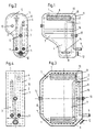
- FIG. 1 and 2 show a heat accumulator 1 with an irregular shape, as it is for could be used in an automobile.
- the lower storage area 4 it has a horizontal cross section which could be almost square, while it increases significantly in length as well as in width and in the upper storage area 5 has a clear rectangular cross section. In this drawn position, the heat accumulator 1 is also installed in the automobile.
- the insulation 6 of the heat accumulator 1 consists of vacuum insulation, which turns out to be the has proven best suited and also has very good long-term effects. Therefore there is the heat accumulator 1 consists of an outer housing 10 and an inner housing 11, which enclose the insulation space 6 in between.
- the vacuum insulation room is with a suitable insulation powder filled that in a known manner via the filler neck 12 Is brought into the isolation space 6 and closed.
- Supports 13 are arranged between the inner 11 and outer housing 10, which can also serve as attachment points of the memory 1.
- the lines 2; 3 go up inside the insulation 6 and break through the inner housing 11 to enter the upper storage space 5. For reasons of space, the line 3 breaks through the inner housing 11 somewhat below the line 2, but as a result no impairment of the insulation effect is to be expected.
- the line 2 extends in an arc within the storage space 7 down to the inlet 14 and carries a charge changing device 8.
- the charge changing device 8 is designed as a swirl outlet, which is shown in FIGS. 5 and 6.
- Line 2 is connected centrally to the swirl outlet. Starting from the center, radially extending blades 140 are provided with a corresponding angle of attack 142, which extend to the circumference 141 of the swirl outlet.
- the inflowing coolant undergoes a horizontally directed deflection and is initially distributed in the lower storage space 4 and then, with the slightest mixing with the warmer coolant present in the storage 1, rise to the top.
- the intermediate floor 87 runs approximately parallel to the floor of the storage space 5 and has sizes of inflow openings adapted to the flow velocity, so that the cooling water initially in the formed by the intermediate floor 87 spreads out upper space before it continues to flow through the inflow openings.
- the Entry or exit of the cooling water into the storage space 4; 5 is done here by input or Outflow slots 88, which lie on the longitudinal edges of the longitudinal walls 84 lying against the floor are arranged.
- the charge changing device 8 in FIGS. 9 to 11 no intermediate floor 87 is provided.
- the liquid is distributed here in space 86 and passes through a series of inflow openings 81 in the longitudinal side lying against the floor of the longitudinal walls 84 into the storage space 7.
- the cutouts of the openings 81 are bent inward and contribute to improving turbulence formation and distribution over the entire length.
- room 86 is replaced by a pointed roof-like termination 85 limited above.
- the longitudinal edges of the roof end 85 extend slightly laterally over the vertical longitudinal walls 84, which is advantageous in terms of flow because the liquid flowing in at the bottom still has a deflection at this point experiences.
- the inflow of the liquid is the charge changing device 8 indirect.
- FIGS. 14 and 15 show a different arrangement of the lines 2; 3rd As best shown in FIG. 15, this memory has a larger width and thus offers sufficient space within the line 2 entering the insulation 6 below the insulation 6 to lead in an arc with sufficient vertical area 16.
- This line enters directly into the lower storage space 4 in order to change the charging device 8 to wear.
- the line 3 goes vertically upwards as in FIGS. 3 and 4 and enters the upper storage space 5.
Landscapes
- Engineering & Computer Science (AREA)
- Physics & Mathematics (AREA)
- Thermal Sciences (AREA)
- Mechanical Engineering (AREA)
- General Engineering & Computer Science (AREA)
- Air-Conditioning For Vehicles (AREA)
- Supply Devices, Intensifiers, Converters, And Telemotors (AREA)
- Body Structure For Vehicles (AREA)
- Transition And Organic Metals Composition Catalysts For Addition Polymerization (AREA)
- Braking Arrangements (AREA)
Description
- Fig. 1 :
- Vorderansicht eines Wärmespeichers mit angepaßter Form
- Fig. 2 :
- Seitenansicht des Wärmespeichers von Fig.1
- Fig. 3 :
- Vorderansicht eines Wärmespeichers mit gleicher Form im oberen und unteren Speicherraum
- Fig. 4 :
- Seitenansicht von Fig.3
- Fig. 5 :
- Vorderansicht des verwendeten Dralldurchlasses
- Fig. 6 :
- Schnitt durch Fig.5
- Fig. 7 :
- Ein langgestrecktes Bauteil als Ladewechselvorrichtung mit einem Zwischenboden
- Fig. 8 :
- Schnitt durch Fig.7
- Fig. 9 :
- Variante von Fig. 7 und 8 ohne Zwischenboden
- Fig.10 :
- Längsschnitt von Fig. 9
- Fig.11 :
- Querschnitt von Fig. 9
- Fig.12 :
- Doppelrohr
- Fig.13 :
- Schnitt durch das Doppelrohr
- Fig.14 :
- Vorderansicht eines Speichers, bei der die eine Leitung einen Bogen inner halb der Isolation aufweist und in den unteren Speicherraum eintritt
- Fig.15 :
- Seitenansicht von Fig. 14
- Fig.16 :
- Entladungsdiagramm
Claims (12)
- Wärmespeicher für ein Kraftfahrzeug, der in dem Kühlmittelkreislauf des Kraftfahrzeuges eingebunden ist und der rhythmisch mittels des Kühlmittels be - und entladbar ist, mit mindestens einem Einlaß (14) und einem Auslaß (15) sowie mit einer den Wärmespeicher umgebenden Vakuumisolation (6), die von mindestens einer Zuflußund einer Abflußleitung (2; 3) durchbrochen wird, wobei der Wärmespeicher (1) ein nach dem Schichtspeicher - Prinzip arbeitender Speicher (1) ist, und der Einlaß (14) und der Auslaß (15) im unteren beziehungsweise oberen Speicherraum (4; 5) angeordnet sind, dadurch gekennzeichnet, daß der Einlaß und des Auslaß jeweils eine Ladewechselvorrichtung (8) gleicher oder verschiedener Konstruktion tragen, deren Gestalt an die gleiche oder unterschiedliche Gestalt aufweisenden Speicherräume (4; 5) angepaßt ist und deren Summe der Strömungsquerschnitte etwa gleich groß ist und daß die Zu - und Abflußleitungen (2;3) sich zumindest über einen in Einbaulage des Wärmespeichers (1) verlaufenden, der Ausbildung einer Temperatur - Sperrschicht dienenden, vertikalen Bereich (16) innerhalb der Vakuumisolation (6) erstrecken.
- Wärmespeicher für ein Kraftfahrzeug nach Anspruch 1, dadurch gekennzeichnet, daß beide Leitungen (2; 3) im unteren Speicherbereich in die Isolation (6) eintreten, sich etwa vertikal innerhalb der Isolation (6) zum oberen Speicherbereich erstrecken, dort mit einem vertikalen Abstand voneinander in den oberen Speicherraum (5) eintreten, von wo eine Leitung (2) zum Auslaß (15) führt und die andere Leitung (3) innerhalb des Speicherraumes (7) nach unten zum Einlaß (14) geführt ist.
- Wärmespeicher nach Anspruch 1, dadurch gekennzeichnet, daß beide Leitungen (2; 3) im unteren Speicherbereich in die Vakuumisolation (6) eintreten, sich etwa vertikal innerhalb der Vakuumisolation (6) zum oberen Speicherbereich erstrecken, daß die Leitung (2) in den oberen Speicherraum (5) eintritt und zum Auslaß (15) führt und daß die Leitung (3) innerhalb der Isolation (6) ein Bogenstück mit ausreichendem vertikalen Bereich (16) aufweist, in den unteren Speicherraum (4) eintritt und direkt zum Einlaß (14) führt.
- Wärmespeicher nach Anspruch 1, dadurch gekennzeichnet, daß beide Leitungen (2;3) im oberen oder mittleren Speicherbereich in die Isolation (6) eintreten, innerhalb der Vakuumisolation (6) bis zu einem Bogen nach unten geführt sind und mit einem ausreichenden vertikalen Bereich (16) nach oben gehen, um in den oberen Speicherraum (5) einzutreten, von wo die Leitung (2) zum Auslaß (15) führt und die andere Leitung (3) innerhalb des Speicherraumes (7) nach unten zum Einlaß (14) geführt ist.
- Wärmespeicher nach den Ansprüchen 1 bis 4, dadurch gekennzeichnet, daß das Speichervolumen etwa 4 bis 15 Itr. beträgt und die Be - und Entladung mit konstanter Strömungsrichtung im Wärmespeicher (1) erfolgt, wobei die Einströmung ausschließlich in dem unteren Speicherraum (4) durchführbar ist.
- Wärmespeicher nach einem der vorstehenden Ansprüche, dadurch gekennzeichnet, daß die Ladewechselvorrichtung (8) als Drallauslaß mit im wesentlichen gleichen Längen - und Breitenabmessungen ausgeführt ist.
- Wärmespeicher nach dem Anspruch 6, dadurch gekennzeichnet, daß der Drallauslaß vorzugsweise kreisförmig ist, mit vom im Zentrum befindlichen Einlaß(14)/Auslaß (15) strahlenförmig ausgehenden und bis zum Umfang (141) reichenden, einen Anstellwinkel (142) aufweisenden Flügeln (140).
- Wärmespeicher nach einem der Ansprüche 1 bis 5, dadurch gekennzeichnet, daß die Ladewechselvorrichtung (8) eine wesentlich größere Länge als Breite aufweist und wenigstens eine Reihe von Ein - bzw. Ausströmöffnungen (81) zur indirekten Einleitung besitzt.
- Wärmespeicher nach Anspruch 8, dadurch gekennzeichnet, daß die Ladewechselvorrichtung (8) aus koaxial angeordneten Rohren (82;83) mit einer Reihe von Ein-bzw Ausströmöffnungen (81) in dem Innenrohr (82) und auf der gegenüberliegenden Seite im Außenrohr (83) besteht.
- Wärmespeicher nach Anspruch 8, dadurch gekennzeichnet, daß die Ladewechselvorrichtung (8) zwei seitliche vertikale Längswände (84) aufweist, die an ihren am Boden des Speicherraumes (4;5) anliegenden Längsseiten eine Reihe von Ein-und Ausströmöffnungen (81) besitzen, wobei die Ausschnitte der Öffnungen (81) nach innen umgebogen sind und, daß die Längswände (84) an ihren Stirnseiten verschlossen sind sowie durch einen sie verbindenden oberen spitzdachartigen Abschluß (85) einen Raum (86) einschließen.
- Wärmespeicher nach Anspruch 8 und 10, dadurch gekennzeichnet, daß der Raum (86) durch einen Ein - bzw. Ausströmöffnungen aufweisenden Zwischenboden (87) unterteilt ist und die am Boden des Speicherraumes (4;5) anliegenden Längsseiten der Längswände (84) mindestens über einen wesentlichen Längenabschnitt reichende Ein- bzw Ausströmschlitze (88) aufweisen.
- Verfahren zum Be - und Entladen eines Wärmespeichers für ein Kraftfahrzeug, gemäß Anspruch 1 oder einem der Ansprüche 2 bis 11, bei dem die Beladung und die Entladung durch Einleiten des Kühlmittels und durch gleichzeitiges Hinausschieben des im Wärmespeicher vorhandenen Kühlmittels durchgeführt wird,
dadurch gekennzeichnet, daß die Entladung des Wärmespeichers (1) durch die Einleitung des kalten Kühlmittels in den unteren Speicherraum (4) und die Beladung durch die Einleitung des warmen Kühlmittels in den oberen Speicherraum (5) mit einer Strömungsgeschwindigkeit von etwa 0,1 bis 0,5 m/s durchgeführt werden und unter Ausnutzung der Temperatur - Schichtung die nahezu vollständige Be - oder Entladung des Wärmespeichers (1) innerhalb von 10 bis 100s erfolgt.
Applications Claiming Priority (3)
| Application Number | Priority Date | Filing Date | Title |
|---|---|---|---|
| DE19530378 | 1995-08-18 | ||
| DE19530378A DE19530378C1 (de) | 1995-08-18 | 1995-08-18 | Wärmespeicher für ein Kraftfahrzeug |
| PCT/DE1996/001356 WO1997006972A1 (de) | 1995-08-18 | 1996-07-24 | Wärmespeicher für ein kraftfahrzeug |
Publications (2)
| Publication Number | Publication Date |
|---|---|
| EP0844936A1 EP0844936A1 (de) | 1998-06-03 |
| EP0844936B1 true EP0844936B1 (de) | 2001-08-08 |
Family
ID=7769775
Family Applications (1)
| Application Number | Title | Priority Date | Filing Date |
|---|---|---|---|
| EP96926998A Expired - Lifetime EP0844936B1 (de) | 1995-08-18 | 1996-07-24 | Wärmespeicher für ein kraftfahrzeug |
Country Status (10)
| Country | Link |
|---|---|
| US (1) | US6056043A (de) |
| EP (1) | EP0844936B1 (de) |
| JP (1) | JPH11512990A (de) |
| AT (1) | ATE203956T1 (de) |
| AU (1) | AU711576B2 (de) |
| DE (1) | DE19530378C1 (de) |
| DK (1) | DK0844936T3 (de) |
| ES (1) | ES2162091T3 (de) |
| NO (1) | NO980075L (de) |
| WO (1) | WO1997006972A1 (de) |
Families Citing this family (10)
| Publication number | Priority date | Publication date | Assignee | Title |
|---|---|---|---|---|
| DE19815777A1 (de) * | 1998-04-08 | 1999-10-14 | Modine Mfg Co | Wärmespeicher, insbesondere Latentwärmespeicher |
| US6053238A (en) * | 1998-10-30 | 2000-04-25 | International Business Machines Corporation | Center feed parallel flow cold plate for dual refrigeration systems |
| JP4469208B2 (ja) * | 2003-12-02 | 2010-05-26 | 株式会社神戸製鋼所 | 熱貯蔵ユニット |
| DE102006037760A1 (de) * | 2006-08-11 | 2008-02-14 | Kali-Umwelttechnik Sondershausen Gmbh | Wärmespeicher mit hoher Entnahmeleistung |
| JP4377963B2 (ja) * | 2007-11-13 | 2009-12-02 | パナソニック株式会社 | 化学蓄熱装置 |
| FR2946419B1 (fr) * | 2009-06-05 | 2014-02-14 | Valeo Systemes Thermiques | Dispositif d'echange thermique et systeme de gestion thermique |
| DE102011050199A1 (de) * | 2011-05-06 | 2012-11-08 | Dbk David + Baader Gmbh | Kühlmittelkreislauf |
| US8863702B2 (en) * | 2011-10-20 | 2014-10-21 | Innovationsschatz Gmbh | Internal combustion engine of an automotive vehicle with a heat storage device that provides reusable heat |
| DE102017210747A1 (de) * | 2017-06-27 | 2018-12-27 | Bayerische Motoren Werke Aktiengesellschaft | Verfahren zum Vorwärmen einer Batterie eines elektrisch betriebenen Kraftfahrzeugs sowie Ladevorrichtung |
| PL249176B1 (pl) * | 2022-11-16 | 2026-03-09 | Lubelska Polt | Ogrzewacz, zwłaszcza do szyb samochodowych |
Family Cites Families (13)
| Publication number | Priority date | Publication date | Assignee | Title |
|---|---|---|---|---|
| US3853270A (en) * | 1973-07-30 | 1974-12-10 | S Prebil | Motor rapid warming device |
| AT332047B (de) * | 1974-09-30 | 1976-09-10 | Laing Nikolaus | Warmespeicher, insbesondere zur klimatisierung von raumen |
| AU501995B2 (en) * | 1975-11-12 | 1979-07-12 | S.W. Hart & Co. Pty. Ltd. | Water container |
| US4037579A (en) * | 1976-01-26 | 1977-07-26 | Chubb Talbot A | Energy storage-boiler tank using salt fusion and heat piping |
| US4082143A (en) * | 1976-04-27 | 1978-04-04 | Thomason Harry E | Solar energy |
| DK26179A (da) * | 1979-01-22 | 1980-07-23 | Eftex Innovation A S | Varmelager |
| NL7905277A (nl) * | 1979-07-05 | 1981-01-07 | Doomernik Bv | Accumulator om warmte of koude op te slaan. |
| JPS5872838A (ja) * | 1981-10-24 | 1983-04-30 | Shimizu Constr Co Ltd | 温度成層型蓄熱槽の給取水装置 |
| DE4007001C2 (de) * | 1990-03-06 | 1994-02-10 | Schatz Oskar | Wärmespeicher, insbesondere für durch Motorabwärme gespeiste Kraftfahrzeugheizungen |
| DE4041626C1 (en) * | 1990-12-22 | 1992-04-30 | Mercedes-Benz Aktiengesellschaft, 7000 Stuttgart, De | Motor vehicle heating system - has hot water tank with intermediate storage facility |
| JPH06213482A (ja) * | 1993-01-12 | 1994-08-02 | Hitachi Ltd | 蓄熱装置及び熱供給システム |
| DE4336190A1 (de) * | 1993-02-19 | 1994-08-25 | Andreas Sebald | Wärmebremse für einen Warmwasserspeicher |
| US5465585A (en) * | 1994-06-16 | 1995-11-14 | Trigen Energy Corporation | Method of low-temperature stratified chilled water storage |
-
1995
- 1995-08-18 DE DE19530378A patent/DE19530378C1/de not_active Expired - Fee Related
-
1996
- 1996-07-24 US US08/809,093 patent/US6056043A/en not_active Expired - Fee Related
- 1996-07-24 JP JP9508706A patent/JPH11512990A/ja active Pending
- 1996-07-24 AT AT96926998T patent/ATE203956T1/de active
- 1996-07-24 AU AU66986/96A patent/AU711576B2/en not_active Ceased
- 1996-07-24 WO PCT/DE1996/001356 patent/WO1997006972A1/de not_active Ceased
- 1996-07-24 ES ES96926998T patent/ES2162091T3/es not_active Expired - Lifetime
- 1996-07-24 EP EP96926998A patent/EP0844936B1/de not_active Expired - Lifetime
- 1996-07-24 DK DK96926998T patent/DK0844936T3/da active
-
1998
- 1998-01-08 NO NO980075A patent/NO980075L/no unknown
Also Published As
| Publication number | Publication date |
|---|---|
| AU711576B2 (en) | 1999-10-14 |
| ATE203956T1 (de) | 2001-08-15 |
| EP0844936A1 (de) | 1998-06-03 |
| DK0844936T3 (da) | 2001-11-12 |
| ES2162091T3 (es) | 2001-12-16 |
| WO1997006972A1 (de) | 1997-02-27 |
| NO980075L (no) | 1998-01-08 |
| US6056043A (en) | 2000-05-02 |
| AU6698696A (en) | 1997-03-12 |
| JPH11512990A (ja) | 1999-11-09 |
| DE19530378C1 (de) | 1997-03-06 |
Similar Documents
| Publication | Publication Date | Title |
|---|---|---|
| DE3523036C2 (de) | ||
| DE19619810A1 (de) | Wärmespeicher mit Rührfunktion | |
| DE102010046482A1 (de) | Wärmetauscher | |
| DE19620441A1 (de) | Motor-Aufwärmvorrichtung für ein Fahrzeug und Wärmeisoliereinrichtung | |
| EP0683362A1 (de) | Wärmespeicher | |
| DE3918596A1 (de) | Verfahren und vorrichtung zur katalytischen behandlung der abgase von verbrennungsmotoren | |
| DE19530378C1 (de) | Wärmespeicher für ein Kraftfahrzeug | |
| DE102005021787A1 (de) | Vorrichtung zur Behandlung des Kältemittels | |
| EP0061697B1 (de) | Kältespeicherelement, Halterungen und Luftregellamellen dafür | |
| DE2854999A1 (de) | Waermeuebertrager | |
| EP0294500B1 (de) | Wärmespeicher, insbesondere für durch Motorabwärme gespeiste Kraftfahrzeugheizungen | |
| EP1936297A2 (de) | Einsatz für einen Warmwasser-Schichtspeicher | |
| DE3990275C1 (de) | Wärmespeicher, insbesondere Latentwärmespeicher für Kraftfahrzeuge | |
| DE3614318A1 (de) | Waermespeicher, insbesondere fuer durch motorabwaerme gespeiste kraftfahrzeugheizungen | |
| DE3718697C2 (de) | Kühlanordnung für eine Brennkraftmaschine eines Fahrzeugs | |
| DE4007001C2 (de) | Wärmespeicher, insbesondere für durch Motorabwärme gespeiste Kraftfahrzeugheizungen | |
| EP1146210B1 (de) | Kastenförmige Kühlanlage für Kraftfahrzeuge | |
| DE3805947A1 (de) | Auspuffeinrichtung zur waermerueckgewinnung bei verbrennungsmotoren | |
| DE19815777A1 (de) | Wärmespeicher, insbesondere Latentwärmespeicher | |
| EP1625298B1 (de) | Kraftfahrzeug und kraftstoffkühler mit lamellenartigen innenstrukturen zum anschluss an die klimaanlage | |
| AT397376B (de) | Wärmetauscher für eine enteisungsvorrichtung sowie verfahren zum erwärmen von enteisungsflüssigkeit | |
| DE102004039626A1 (de) | Speichervorrichtung für thermische Energie und Verfahren zur Speicherung von thermischer Energie | |
| EP1741888B1 (de) | Vorratsbehälter eines Kraftfahrzeugs | |
| DE69706970T2 (de) | Kältespeicher | |
| DE102005047029A1 (de) | Wärmespeichertank mit verbesserter Wärmeisolierleistung |
Legal Events
| Date | Code | Title | Description |
|---|---|---|---|
| PUAI | Public reference made under article 153(3) epc to a published international application that has entered the european phase |
Free format text: ORIGINAL CODE: 0009012 |
|
| 17P | Request for examination filed |
Effective date: 19970819 |
|
| AK | Designated contracting states |
Kind code of ref document: A1 Designated state(s): AT DK ES FI FR GB IT NL SE |
|
| RAP1 | Party data changed (applicant data changed or rights of an application transferred) |
Owner name: MODINE MANUFACTURING COMPANY |
|
| 17Q | First examination report despatched |
Effective date: 19990616 |
|
| GRAG | Despatch of communication of intention to grant |
Free format text: ORIGINAL CODE: EPIDOS AGRA |
|
| GRAH | Despatch of communication of intention to grant a patent |
Free format text: ORIGINAL CODE: EPIDOS IGRA |
|
| GRAH | Despatch of communication of intention to grant a patent |
Free format text: ORIGINAL CODE: EPIDOS IGRA |
|
| GRAA | (expected) grant |
Free format text: ORIGINAL CODE: 0009210 |
|
| AK | Designated contracting states |
Kind code of ref document: B1 Designated state(s): AT DK ES FI FR GB IT NL SE |
|
| REF | Corresponds to: |
Ref document number: 203956 Country of ref document: AT Date of ref document: 20010815 Kind code of ref document: T |
|
| REG | Reference to a national code |
Ref country code: DK Ref legal event code: T3 |
|
| GBT | Gb: translation of ep patent filed (gb section 77(6)(a)/1977) |
Effective date: 20011106 |
|
| REG | Reference to a national code |
Ref country code: ES Ref legal event code: FG2A Ref document number: 2162091 Country of ref document: ES Kind code of ref document: T3 |
|
| REG | Reference to a national code |
Ref country code: GB Ref legal event code: IF02 |
|
| ET | Fr: translation filed | ||
| PLBE | No opposition filed within time limit |
Free format text: ORIGINAL CODE: 0009261 |
|
| STAA | Information on the status of an ep patent application or granted ep patent |
Free format text: STATUS: NO OPPOSITION FILED WITHIN TIME LIMIT |
|
| 26N | No opposition filed | ||
| PGFP | Annual fee paid to national office [announced via postgrant information from national office to epo] |
Ref country code: SE Payment date: 20130725 Year of fee payment: 18 Ref country code: AT Payment date: 20130723 Year of fee payment: 18 Ref country code: FI Payment date: 20130723 Year of fee payment: 18 Ref country code: NL Payment date: 20130725 Year of fee payment: 18 Ref country code: ES Payment date: 20130704 Year of fee payment: 18 Ref country code: DK Payment date: 20130722 Year of fee payment: 18 |
|
| PGFP | Annual fee paid to national office [announced via postgrant information from national office to epo] |
Ref country code: GB Payment date: 20130724 Year of fee payment: 18 Ref country code: FR Payment date: 20130719 Year of fee payment: 18 |
|
| PGFP | Annual fee paid to national office [announced via postgrant information from national office to epo] |
Ref country code: IT Payment date: 20130725 Year of fee payment: 18 |
|
| REG | Reference to a national code |
Ref country code: DK Ref legal event code: EBP Effective date: 20140731 |
|
| REG | Reference to a national code |
Ref country code: NL Ref legal event code: V1 Effective date: 20150201 |
|
| REG | Reference to a national code |
Ref country code: SE Ref legal event code: EUG |
|
| REG | Reference to a national code |
Ref country code: AT Ref legal event code: MM01 Ref document number: 203956 Country of ref document: AT Kind code of ref document: T Effective date: 20140724 |
|
| GBPC | Gb: european patent ceased through non-payment of renewal fee |
Effective date: 20140724 |
|
| PG25 | Lapsed in a contracting state [announced via postgrant information from national office to epo] |
Ref country code: NL Free format text: LAPSE BECAUSE OF NON-PAYMENT OF DUE FEES Effective date: 20150201 |
|
| REG | Reference to a national code |
Ref country code: FR Ref legal event code: ST Effective date: 20150331 |
|
| PG25 | Lapsed in a contracting state [announced via postgrant information from national office to epo] |
Ref country code: IT Free format text: LAPSE BECAUSE OF NON-PAYMENT OF DUE FEES Effective date: 20140724 Ref country code: FI Free format text: LAPSE BECAUSE OF NON-PAYMENT OF DUE FEES Effective date: 20140724 |
|
| PG25 | Lapsed in a contracting state [announced via postgrant information from national office to epo] |
Ref country code: SE Free format text: LAPSE BECAUSE OF NON-PAYMENT OF DUE FEES Effective date: 20140725 Ref country code: AT Free format text: LAPSE BECAUSE OF NON-PAYMENT OF DUE FEES Effective date: 20140724 Ref country code: FR Free format text: LAPSE BECAUSE OF NON-PAYMENT OF DUE FEES Effective date: 20140731 Ref country code: GB Free format text: LAPSE BECAUSE OF NON-PAYMENT OF DUE FEES Effective date: 20140724 |
|
| PG25 | Lapsed in a contracting state [announced via postgrant information from national office to epo] |
Ref country code: DK Free format text: LAPSE BECAUSE OF NON-PAYMENT OF DUE FEES Effective date: 20140731 |
|
| REG | Reference to a national code |
Ref country code: ES Ref legal event code: FD2A Effective date: 20150827 |
|
| PG25 | Lapsed in a contracting state [announced via postgrant information from national office to epo] |
Ref country code: ES Free format text: LAPSE BECAUSE OF NON-PAYMENT OF DUE FEES Effective date: 20140725 |