EP0843390A2 - Universell verwendbare Handsickenzange - Google Patents
Universell verwendbare Handsickenzange Download PDFInfo
- Publication number
- EP0843390A2 EP0843390A2 EP97111216A EP97111216A EP0843390A2 EP 0843390 A2 EP0843390 A2 EP 0843390A2 EP 97111216 A EP97111216 A EP 97111216A EP 97111216 A EP97111216 A EP 97111216A EP 0843390 A2 EP0843390 A2 EP 0843390A2
- Authority
- EP
- European Patent Office
- Prior art keywords
- die
- hand
- shaped
- double
- crimping
- Prior art date
- Legal status (The legal status is an assumption and is not a legal conclusion. Google has not performed a legal analysis and makes no representation as to the accuracy of the status listed.)
- Granted
Links
Images


Classifications
-
- B—PERFORMING OPERATIONS; TRANSPORTING
- B26—HAND CUTTING TOOLS; CUTTING; SEVERING
- B26F—PERFORATING; PUNCHING; CUTTING-OUT; STAMPING-OUT; SEVERING BY MEANS OTHER THAN CUTTING
- B26F1/00—Perforating; Punching; Cutting-out; Stamping-out; Apparatus therefor
- B26F1/32—Hand-held perforating or punching apparatus, e.g. awls
- B26F1/36—Punching or perforating pliers
-
- B—PERFORMING OPERATIONS; TRANSPORTING
- B25—HAND TOOLS; PORTABLE POWER-DRIVEN TOOLS; MANIPULATORS
- B25B—TOOLS OR BENCH DEVICES NOT OTHERWISE PROVIDED FOR, FOR FASTENING, CONNECTING, DISENGAGING, OR HOLDING
- B25B7/00—Pliers; Other hand-held gripping tools with jaws on pivoted limbs; Details applicable generally to pivoted-limb hand tools
- B25B7/02—Jaws
-
- B—PERFORMING OPERATIONS; TRANSPORTING
- B25—HAND TOOLS; PORTABLE POWER-DRIVEN TOOLS; MANIPULATORS
- B25B—TOOLS OR BENCH DEVICES NOT OTHERWISE PROVIDED FOR, FOR FASTENING, CONNECTING, DISENGAGING, OR HOLDING
- B25B7/00—Pliers; Other hand-held gripping tools with jaws on pivoted limbs; Details applicable generally to pivoted-limb hand tools
- B25B7/12—Pliers; Other hand-held gripping tools with jaws on pivoted limbs; Details applicable generally to pivoted-limb hand tools involving special transmission means between the handles and the jaws, e.g. toggle levers, gears
-
- H—ELECTRICITY
- H01—ELECTRIC ELEMENTS
- H01R—ELECTRICALLY-CONDUCTIVE CONNECTIONS; STRUCTURAL ASSOCIATIONS OF A PLURALITY OF MUTUALLY-INSULATED ELECTRICAL CONNECTING ELEMENTS; COUPLING DEVICES; CURRENT COLLECTORS
- H01R43/00—Apparatus or processes specially adapted for manufacturing, assembling, maintaining, or repairing of line connectors or current collectors or for joining electric conductors
- H01R43/04—Apparatus or processes specially adapted for manufacturing, assembling, maintaining, or repairing of line connectors or current collectors or for joining electric conductors for forming connections by deformation, e.g. crimping tool
- H01R43/042—Hand tools for crimping
- H01R43/0421—Hand tools for crimping combined with other functions, e.g. cutting
-
- B—PERFORMING OPERATIONS; TRANSPORTING
- B26—HAND CUTTING TOOLS; CUTTING; SEVERING
- B26F—PERFORATING; PUNCHING; CUTTING-OUT; STAMPING-OUT; SEVERING BY MEANS OTHER THAN CUTTING
- B26F1/00—Perforating; Punching; Cutting-out; Stamping-out; Apparatus therefor
- B26F1/32—Hand-held perforating or punching apparatus, e.g. awls
- B26F1/36—Punching or perforating pliers
- B26F2001/365—Punching or perforating pliers hand held pliers with handles
Definitions
- the invention relates to a universal hand pliers, which are characterized by the Interchangeability of different dies and pressing tools for versatile cold forming of sheet metal and U profiles, in particular ceiling and wall profiles or for example, also suitable for crimping.
- punch pliers are used to punch openings, especially in plastic cans (OS DE 195 05 613), known or a beading device for the production of beaded electrical connections according to AS 1144804. It is not with any of the known devices However, it is possible to insert appropriate beads in the sheet metal U-profiles or the special one Use beading device for other cold forming operations.
- the invention has therefore set itself the task of one for a wide variety of operations to develop the cold forming universally applicable hand crimping pliers with the thin-walled Sheet metal and U profiles, e.g. appropriately prepared ceilings CD or U profiles, as they are common in drywall construction, to be able to work on the spot, that with it a vertical or horizontal bending and thus manufacture of any desired Radius is possible and which is also suitable for other operations suitable, for example for crimping.
- the object is achieved in that a basic element as a static part, for example made of U-shaped steel sheet, and angled on its front and is tapered that a fastening and Guide part has arisen.
- a basic element as a static part, for example made of U-shaped steel sheet, and angled on its front and is tapered that a fastening and Guide part has arisen.
- the upper part of the fastening and guide part is one right-angled and L-shaped die receptacle with a face firmly attached to it Screw bolts introduced as a holder for a die lock.
- a sliding mount in which a flat steel one existing shaft connected with a notched bead wedge is accommodated.
- The serves Underside of the L-shaped part of the die holder and a bolt that is also used as a stop for a lever with a grip element, as a guide.
- the front of a U-shaped lever for power transmission is designed so that between a hinge point mounted in the base element and a connecting hinge pin as a fulcrum a lever arm is created, the force of which is via a double-sided connecting rod with a stud as a hinge point, on the shaft and thus, for example, on the Notch bead wedge is transferred.
- the die lock is with one or more locking holes provided and on the part drilled for the bolt, for improvement of the locking process in the locking holes on the die holder pushed-on dies, slightly cranked.
- a coil spring picked up by the bolt, which is located between the die lock and the upper edge of the basic element, also facilitates the snap-in process.
- the notched bead wedge is either fixed or releasably connected to the shaft, so that at any time depending on the conditions of use, an interchangeability either of the notched bead wedge or at permanent connections of the entire shaft-pressing tool unit, is possible.
- the dies that can be pushed onto the die holder via passage guides for example Double-function dies can be pushed onto the die holder in such a way that the respective one Die cutout corresponds to the opposite notched bead wedge. That is, through the Appropriate application and combination of the respective dies are the most varied Beads, such as edge and bottom beads for the production of wall and ceiling profiles, can be inserted.
- a double-function die with locking pins has one on one side Die cutout and on the opposite side a notched bead wedge so that it in the respective pressing process either only as a locking device arranged in front of it Double-function die or serves with the die holder or your own Notched bead wedge itself can be used as a shaping tool.
- One on the die holder if necessary slidably arranged double-function die is with die holders on both sides Mistake. However, one side has an additional recess, so that the die recess this side is open at the top and so there is free space for the profile to be processed or for combination with other double function dies.
- the shaft is provided with a crimp head instead of a notched bead wedge and finds it a working part slid onto the die holder and extended with an L-shape locked crimping die use
- the hand crimping pliers are also used as crimping pliers changeable.
- the hand crimping pliers consist of a static part, as a basic element 1.
- the basic element 1 made of U-shaped steel sheet and open at the top is so angled in the front part and tapers so that through the resulting outer sides 2 a fastening and guiding part 3 is created.
- the upper part of the fastening and Guide part 3 is used to attach a rectangular die holder 4 with an L-shaped screw part, and the lower part of the fastening and Guide part 3 as a sliding mount for an existing flat steel, with a Notched bead wedge 5 firmly connected shaft 6.
- a coil spring 14 with washer 15 is introduced.
- the U-shaped lever 16 is slightly cranked towards the handle side and its front is designed so that between the bearings on both sides in the base element 1 and with washers screwed hinge point 17 and a connecting hinge pin 18 as a fulcrum, a lever arm arises, the forces of which are via a double-sided connecting rod 19 via a Stud 20 is transferred to the shaft 6 and thus to the notched bead wedge 5.
- the Connecting rod 19 resting on both sides of the shaft 6 is by using the stud screw 20 exchangeable at any time.
- a bolt 21, which is also located in the base element 1, serves on the one hand the lever 16 as Stop and on the other hand, as the L-shaped screw part of the die holder 4, as Guide element for the shaft 6.
- the necessary stability in the front working area of the hand crimping tool results from Screwing the outer sides 2 together with the L-shaped screw part inserted therein the die holder 4 by means of connecting screws 22.
- a dual function die 12 for U-profiles and edge beads take over with its flat side over the in the locking hole 8 locked locking pin 11 the locking.
- the slidable double-function die 23 is pushed on that the smooth side with the die recess 25 is opposite the notched bead wedge 5 and the other offset recess 25 with the recess 26 opposite the notch bead 28 of the double-function die, which has also been postponed and locked 12, is arranged.
- crimping pliers shows a further possibility for universal use of the crimping pliers, in which, instead of the double-function dies, a crimp die 13 on the die holder 4 pushed on and locked via a locking hole 8 of the die lock 9 becomes.
- the shaft 6 was replaced with notched bead wedge 5 and by one Shank 6 replaced with crimping head 31 as a stamped part.
- the crimping die 13 is designed so that the working part 32 is advanced so far that there is enough space for the work to be done Workpiece is available.
Landscapes
- Engineering & Computer Science (AREA)
- Mechanical Engineering (AREA)
- Life Sciences & Earth Sciences (AREA)
- Forests & Forestry (AREA)
- Manufacturing & Machinery (AREA)
- Gripping Jigs, Holding Jigs, And Positioning Jigs (AREA)
- Hand Tools For Fitting Together And Separating, Or Other Hand Tools (AREA)
- Connection Of Plates (AREA)
- Clamps And Clips (AREA)
Abstract
Description
- Fig. 1
- eine Ausführungsform der erfindungsgemäßen Handsickenzange in Seitenansicht (teilweise im Schnitt) mit den verschiedensten aufschiebbaren Gesenken
- Fig. 2
- Teilausschnitte als Draufsicht des unteren Teiles nach Fig. 1
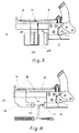
- Fig. 3
- Anordnung eines aufgeschobenen und verschiebbar angeordneten Doppelfunktionsgesenkes für Boden- und Randsicken und eines in diesem Fall zur Arretierung dienenden gleichfalls aufgeschobenen Doppelfunktionsgesenkes für U-Profile und Randsicken zum Eindrücken von Bodensicken in ein eingelegtes U-Profil
- Fig. 4
- Anordnung eines aufgeschobenen Doppelfunktionsgesenkes für Boden- und Randsicken dessen Einschnitt sich gegenüber des Kerbsickenkeiles des gleichfalls aufgeschobenen und arretierten Doppelfunktionsgesenkes für Boden- und U-Profile befindet zum beidseitigen Drücken eines eingelegten doppelseitigen U-Profiles
- Fig. 5
- ein aufgeschobenes und arretiertes Doppelfunktionsgesenk für U-Profile und Randsicken, welches mit seiner Negativseite dem Kerbsickenkeil gegenüber angeordnet ist zum Verformen von U-Wandprofilen
- Fig. 6
- ein aufgeschobenes und arretiertes Crimpgesenk, welches gegenüber einem eingebrachten Crimpstanzteil angeordnet ist
- 01 =
- Grundelement
- 02 =
- Außenseiten
- 03 =
- Befestigungs- und Führungsteil
- 04 =
- Gesenkaufnahme
- 05 =
- Kerbsickenkeil
- 06 =
- Schaft
- 07 =
- Schraubbolzen
- 08 =
- Arretierungsbohrung
- 09 =
- Gesenkarretierung
- 10 =
- Mutter
- 11 =
- Arretierungsstift
- 12 =
- Doppelfunktionsgesenk
- 13 =
- Crimpgesenk
- 14 =
- Spiralfeder
- 15 =
- Unterlegscheibe
- 16 =
- Hebel
- 17 =
- Gelenkpunkt
- 18 =
- Verbindungsgelenk/Stift
- 19 =
- Pleuelstange
- 20 =
- Stiftschraube
- 21 =
- Bolzen
- 22 =
- Verbindungsschraube
- 23 =
- Doppelfunktionsgesenk für Boden- und Wandsicken
- 24 =
- Durchgangsführung
- 25 =
- Gesenkaussparung
- 26 =
- Aussparung
- 27 =
- C-Profil
- 28 =
- Kerbsickenkeil
- 29 =
- Gesenkaussparung
- 30 =
- U-Wandprofil
- 31 =
- Crimpkopf
- 32 =
- Arbeitsteil
Claims (8)
- Universell verwendbare Handsickenzange, dadurch gekennzeichnet, daß ein Grundelement (1) als statischer Teil, beispielsweise aus U-förmigen Stahlblech, an seiner Vorderseite so abgewinkelt und verjüngt ist, daß durch die sich so ergebenden parallelen Außenseiten (2) ein Befestigungs- und Führungsteil (3) entstanden ist, in welches einerseits im oberen Teil eine rechtwinklige und L-förmige Gesenkaufnahme (4) mit einem stirnseitig daran fest verbundenen Schraubbolzen (7) als Halterung für eine Gesenkarretierung (9) eingebracht ist und andererseits im unteren Teil eine Gleitaufnahme, in der ein aus Flachstahl bestehender einem Kerbsickenkeil (5) fest verbundener Schaft (6) aufgenommen wird, der durch die Unterseite des L-förmig ausgebildeten Teiles der Gesenkaufnahme (4) sowie durch einen Bolzen (21), der gleichzeitig auch als Anschlag für einen Hebel (16) mit Griffelement dient, geführt wird, wobei die Kraftübertragung über einen gleichfalls U-förmigen Hebel (16), dessen Vorderseite so gestaltet ist, daß zwischen einem im Grundelement (1) gelagerten Gelenkpunkt (17) und einem Verbindungsgelenkstift (18) als Drehpunkt ein Hebelarm entsteht, dessen Kraft über eine doppelseitige Pleuelstange (19) mit einer Stiftschraube (20) als Gelenkpunkt, auf den Schaft (6) und damit beispielsweise auf den Kerbsickenkeil (5) übertragbar wird, erfolgt.
- Handsickenzange nach Anspruch 1, dadurch gekennzeichnet, daß die Gesenkarretierung (9) mit einer oder mehrenen Arretierungsbohrungen (8) versehen ist.
- Handsickenzange nach Anspruch 1 und 2, dadurch gekennzeichnet, daß die Gesenkarretierung (9) an dem für den Schraubbolzen (7) durchbohrten Teil leicht gekröpft ist, so daß die Beweglichkeit noch durch eine vom Schraubbolzen (7) aufgenommene Spiralfeder (14) mit Unterlegscheibe (15), die sich zwischen der Gesenkarretierung (9) und der Oberkante des Grundelementes (1) befindet, verbessert wird.
- Handsickenzange nach Anspruch 1, dadurch gekennzeichnet, daß der Kerbsickenkeil (5) entweder fest oder lösbar mit dem Schaft (6) verbunden ist.
- Handsickenzange nach einem oder mehreren Ansprüchen 1 bis 4, dadurch gekennzeichnet, daß über Durchgangsführungen (24) auf die Gesenkaufnahme (4) aufschiebbare Gesenke, beispielsweise Doppelfunktionsgesenke (12;23) so auf die Gesenkaufnahme (4) aufschiebbar sind, daß die jeweilige Gesenkaussparung (25;29) dem gegenüberliegenden Kerbsickenkeil (5) entspricht.
- Handsickenzange nach einem oder mehreren Ansprüchen 1 bis 5, dadurch gekennzeichnet, daß das mit einem Arretierungsstift (11) versehene Doppelfunktionsgesenk (12) auf der einen Seite eine Gesenkaussparung (29) und an der gegenüberliegenden Seite einen Kerbsickenkeil (28) aufweist.
- Handsickenzange nach einem oder mehreren Ansprüchen 1 bis 6, dadurch gekennzeichnet, daß das im Bedarfsfall auf der Gesenkaufnahme (4) verschiebbar angeordnete Doppelfunktionsgesenk (23) beidseitig mit Gesenkaussparungen (25) versehen ist, wobei eine Seite zusätzlich eine Aussparung (26) aufweist, so daß die Gesenkaussparung (25) dieser Seite nach oben offen ist.
- Handsickenzange nach einem oder mehreren Ansprüchen 1 bis 7, dadurch gekennzeichnet, daß ein Schaft (6) statt eines Kerbsickenkeiles (5) einen Crimpkopf (31) aufweist, der einem auf der Gesenkaufnahme (4) aufgeschobenen und arretierten Arbeitsteil (32) des Crimpgesenkes (13) entspricht, wobei der Arbeitsteil (32) des Crimpgesenkes (13) L-förmig verlängert ist.
Applications Claiming Priority (2)
| Application Number | Priority Date | Filing Date | Title |
|---|---|---|---|
| DE19646785A DE19646785C1 (de) | 1996-11-13 | 1996-11-13 | Handsickenzange mit auswechselbarem Gesenk |
| DE19646785 | 1996-11-13 |
Publications (3)
| Publication Number | Publication Date |
|---|---|
| EP0843390A2 true EP0843390A2 (de) | 1998-05-20 |
| EP0843390A3 EP0843390A3 (de) | 1998-06-03 |
| EP0843390B1 EP0843390B1 (de) | 2000-11-15 |
Family
ID=7811471
Family Applications (1)
| Application Number | Title | Priority Date | Filing Date |
|---|---|---|---|
| EP97111216A Expired - Lifetime EP0843390B1 (de) | 1996-11-13 | 1997-07-03 | Universell verwendbare Handsickenzange |
Country Status (2)
| Country | Link |
|---|---|
| EP (1) | EP0843390B1 (de) |
| DE (2) | DE19646785C1 (de) |
Families Citing this family (1)
| Publication number | Priority date | Publication date | Assignee | Title |
|---|---|---|---|---|
| GB2438467B (en) * | 2006-05-25 | 2010-12-29 | Blue Sky Access Ltd | A crimping tool for use on a metal roof panel |
Family Cites Families (6)
| Publication number | Priority date | Publication date | Assignee | Title |
|---|---|---|---|---|
| BE533170A (de) * | 1953-11-10 | |||
| DE7205611U (de) * | 1972-02-15 | 1972-05-04 | Huber & Suhner Ag | Klemmzange insbesondere für Kabelverbindungen |
| DE2728454C3 (de) * | 1977-06-24 | 1981-06-25 | Fritz 6703 Limburghof Knebel | Rohrzange |
| DE3105262A1 (de) * | 1981-02-13 | 1982-09-02 | Bessey & Sohn Gmbh & Co, 7000 Stuttgart | Werkzeug zum verformen, druecken oder zur durchfuehrung anderer arbeitsgaenge unter anwendung von druck |
| WO1984004475A1 (en) * | 1983-05-09 | 1984-11-22 | David Meikle | Forming tool |
| DD225655B1 (de) * | 1984-04-10 | 1987-07-08 | Adw Ddr | Presszange zum zusammendruecken von rohr- oder huelsenfoermigen werkstuecken |
-
1996
- 1996-11-13 DE DE19646785A patent/DE19646785C1/de not_active Expired - Fee Related
-
1997
- 1997-07-03 EP EP97111216A patent/EP0843390B1/de not_active Expired - Lifetime
- 1997-07-03 DE DE59702638T patent/DE59702638D1/de not_active Expired - Fee Related
Also Published As
| Publication number | Publication date |
|---|---|
| DE59702638D1 (de) | 2000-12-21 |
| EP0843390A3 (de) | 1998-06-03 |
| EP0843390B1 (de) | 2000-11-15 |
| DE19646785C1 (de) | 1998-03-05 |
Similar Documents
| Publication | Publication Date | Title |
|---|---|---|
| DE60008149T2 (de) | Sicherheitswerkzeug zum unterstützen und halten wenigstens eines auswechselbaren werkzeugs, insbesondere für eine biegepresse | |
| EP1445059B1 (de) | Funktionselement, insbesondere Befestigungselement und ein aus dem Funktionselement und einem Blechteil bestehenden Zusammenbauteil | |
| EP3434331B1 (de) | Hydraulisches arbeitsgerät | |
| EP1366304A2 (de) | Selbststanzender niet, verfahren und vorrichtung zum setzen eines nietelements und seine verwendung | |
| AT515267B1 (de) | Aufsatz für eine Pressvorrichtung | |
| DE202016007588U1 (de) | Einschraubhilfe zum Halten und Ausrichten einer Schraube | |
| DE29825182U1 (de) | Vorrichtung zum Entfernen von Ausbrechteilen aus einem Werkstoffbogen o.dgl. | |
| DE102016014860B3 (de) | Einschraubhilfe zum Halten und Ausrichten einer Schraube | |
| EP3269509B1 (de) | Trapezlochzange | |
| EP2883658A2 (de) | Aufsatz für eine Pressvorrichtung | |
| DE102007009618B4 (de) | Setzvorrichtung für eine Befestigungseinheit | |
| EP0843390B1 (de) | Universell verwendbare Handsickenzange | |
| DE2540856C2 (de) | Verfahren und Vorrichtung zum Anschlagen einer Fahrzeugtür | |
| DE4424493C2 (de) | Zangenartiges Werkzeug zum formschlüssigen Verbinden von Blechteilen | |
| EP4303381A1 (de) | Verschiebvorrichtung zum lösen von grossflächigen dach-faserzement-wellplatten | |
| EP0158062A1 (de) | Werkzeug zum Crimpen Schneiden, Pressen o. dgl. | |
| DE102015212839B3 (de) | Vorrichtung zum Anbringen von Löchern in Blechteilen | |
| EP4030103B1 (de) | Kochfeld mit steuerungsgehäuse | |
| DE69414749T2 (de) | Befestigungsvorrichtung | |
| EP2045041B1 (de) | Handhabungsvorrichtung für einen Werkzeughalter mit einer Führungseinrichtung | |
| DE10054752A1 (de) | Crimpdurchbruchgesenk mit Crimpdurchbruchkopf als universelles Werkzeug zum Crimpen und Lochen | |
| DE202007018107U1 (de) | Vorrichtung zum Öffnen von Nuten | |
| DE102007063030A1 (de) | Vorrichtung zum Öffnen von Nuten | |
| DE10259871B4 (de) | Handbetätigte Bearbeitungsvorrichtung unter Verwendung eines Parallelschraubstocks | |
| CH718013B1 (de) | Werkzeug zum Eindrücken von Blechbauteilen und Verfahren zur Montage von Kanalrahmen auf Kanalelementen von Lüftungskanälen. |
Legal Events
| Date | Code | Title | Description |
|---|---|---|---|
| PUAI | Public reference made under article 153(3) epc to a published international application that has entered the european phase |
Free format text: ORIGINAL CODE: 0009012 |
|
| PUAL | Search report despatched |
Free format text: ORIGINAL CODE: 0009013 |
|
| AK | Designated contracting states |
Kind code of ref document: A2 Designated state(s): DE FR GB IT NL SE |
|
| AX | Request for extension of the european patent |
Free format text: AL;LT;LV;RO;SI |
|
| AK | Designated contracting states |
Kind code of ref document: A3 Designated state(s): AT BE CH DE DK ES FI FR GB GR IE IT LI LU MC NL PT SE |
|
| AX | Request for extension of the european patent |
Free format text: AL;LT;LV;RO;SI |
|
| 17P | Request for examination filed |
Effective date: 19981103 |
|
| AKX | Designation fees paid |
Free format text: DE FR GB IT NL SE |
|
| RBV | Designated contracting states (corrected) |
Designated state(s): DE FR GB IT NL SE |
|
| 17Q | First examination report despatched |
Effective date: 19990202 |
|
| GRAG | Despatch of communication of intention to grant |
Free format text: ORIGINAL CODE: EPIDOS AGRA |
|
| GRAG | Despatch of communication of intention to grant |
Free format text: ORIGINAL CODE: EPIDOS AGRA |
|
| GRAG | Despatch of communication of intention to grant |
Free format text: ORIGINAL CODE: EPIDOS AGRA |
|
| GRAH | Despatch of communication of intention to grant a patent |
Free format text: ORIGINAL CODE: EPIDOS IGRA |
|
| GRAH | Despatch of communication of intention to grant a patent |
Free format text: ORIGINAL CODE: EPIDOS IGRA |
|
| GRAA | (expected) grant |
Free format text: ORIGINAL CODE: 0009210 |
|
| AK | Designated contracting states |
Kind code of ref document: B1 Designated state(s): DE FR GB IT NL SE |
|
| ITF | It: translation for a ep patent filed | ||
| ET | Fr: translation filed | ||
| REF | Corresponds to: |
Ref document number: 59702638 Country of ref document: DE Date of ref document: 20001221 |
|
| GBT | Gb: translation of ep patent filed (gb section 77(6)(a)/1977) |
Effective date: 20001212 |
|
| PLBE | No opposition filed within time limit |
Free format text: ORIGINAL CODE: 0009261 |
|
| STAA | Information on the status of an ep patent application or granted ep patent |
Free format text: STATUS: NO OPPOSITION FILED WITHIN TIME LIMIT |
|
| 26N | No opposition filed | ||
| REG | Reference to a national code |
Ref country code: GB Ref legal event code: IF02 |
|
| PGFP | Annual fee paid to national office [announced via postgrant information from national office to epo] |
Ref country code: GB Payment date: 20020610 Year of fee payment: 6 |
|
| PGFP | Annual fee paid to national office [announced via postgrant information from national office to epo] |
Ref country code: NL Payment date: 20020717 Year of fee payment: 6 Ref country code: FR Payment date: 20020717 Year of fee payment: 6 |
|
| PGFP | Annual fee paid to national office [announced via postgrant information from national office to epo] |
Ref country code: SE Payment date: 20020723 Year of fee payment: 6 |
|
| PGFP | Annual fee paid to national office [announced via postgrant information from national office to epo] |
Ref country code: DE Payment date: 20020920 Year of fee payment: 6 |
|
| PG25 | Lapsed in a contracting state [announced via postgrant information from national office to epo] |
Ref country code: GB Free format text: LAPSE BECAUSE OF NON-PAYMENT OF DUE FEES Effective date: 20030703 |
|
| PG25 | Lapsed in a contracting state [announced via postgrant information from national office to epo] |
Ref country code: SE Free format text: LAPSE BECAUSE OF NON-PAYMENT OF DUE FEES Effective date: 20030704 |
|
| PG25 | Lapsed in a contracting state [announced via postgrant information from national office to epo] |
Ref country code: NL Free format text: LAPSE BECAUSE OF NON-PAYMENT OF DUE FEES Effective date: 20040201 |
|
| PG25 | Lapsed in a contracting state [announced via postgrant information from national office to epo] |
Ref country code: DE Free format text: LAPSE BECAUSE OF NON-PAYMENT OF DUE FEES Effective date: 20040203 |
|
| GBPC | Gb: european patent ceased through non-payment of renewal fee |
Effective date: 20030703 |
|
| EUG | Se: european patent has lapsed | ||
| PG25 | Lapsed in a contracting state [announced via postgrant information from national office to epo] |
Ref country code: FR Free format text: LAPSE BECAUSE OF NON-PAYMENT OF DUE FEES Effective date: 20040331 |
|
| NLV4 | Nl: lapsed or anulled due to non-payment of the annual fee |
Effective date: 20040201 |
|
| REG | Reference to a national code |
Ref country code: FR Ref legal event code: ST |
|
| PG25 | Lapsed in a contracting state [announced via postgrant information from national office to epo] |
Ref country code: IT Free format text: LAPSE BECAUSE OF NON-PAYMENT OF DUE FEES;WARNING: LAPSES OF ITALIAN PATENTS WITH EFFECTIVE DATE BEFORE 2007 MAY HAVE OCCURRED AT ANY TIME BEFORE 2007. THE CORRECT EFFECTIVE DATE MAY BE DIFFERENT FROM THE ONE RECORDED. Effective date: 20050703 |