EP0841527A2 - Dampfkondensator - Google Patents
Dampfkondensator Download PDFInfo
- Publication number
- EP0841527A2 EP0841527A2 EP97810703A EP97810703A EP0841527A2 EP 0841527 A2 EP0841527 A2 EP 0841527A2 EP 97810703 A EP97810703 A EP 97810703A EP 97810703 A EP97810703 A EP 97810703A EP 0841527 A2 EP0841527 A2 EP 0841527A2
- Authority
- EP
- European Patent Office
- Prior art keywords
- bundle
- steam
- condenser
- bundles
- sub
- Prior art date
- Legal status (The legal status is an assumption and is not a legal conclusion. Google has not performed a legal analysis and makes no representation as to the accuracy of the status listed.)
- Ceased
Links
- 239000007789 gas Substances 0.000 claims abstract description 13
- XLYOFNOQVPJJNP-UHFFFAOYSA-N water Substances O XLYOFNOQVPJJNP-UHFFFAOYSA-N 0.000 claims abstract description 8
- 239000011261 inert gas Substances 0.000 claims description 14
- 239000000203 mixture Substances 0.000 claims description 8
- 239000000498 cooling water Substances 0.000 claims description 5
- 230000004807 localization Effects 0.000 claims description 4
- 239000011796 hollow space material Substances 0.000 abstract 1
- 239000003990 capacitor Substances 0.000 description 6
- 230000008901 benefit Effects 0.000 description 5
- 238000009825 accumulation Methods 0.000 description 4
- 230000035508 accumulation Effects 0.000 description 4
- 238000009833 condensation Methods 0.000 description 4
- 230000005494 condensation Effects 0.000 description 4
- QVGXLLKOCUKJST-UHFFFAOYSA-N atomic oxygen Chemical compound [O] QVGXLLKOCUKJST-UHFFFAOYSA-N 0.000 description 2
- 230000000694 effects Effects 0.000 description 2
- 238000001704 evaporation Methods 0.000 description 2
- 239000001301 oxygen Substances 0.000 description 2
- 229910052760 oxygen Inorganic materials 0.000 description 2
- 238000011084 recovery Methods 0.000 description 2
- 238000004781 supercooling Methods 0.000 description 2
- 230000001133 acceleration Effects 0.000 description 1
- 238000007872 degassing Methods 0.000 description 1
- 230000008020 evaporation Effects 0.000 description 1
- 238000011010 flushing procedure Methods 0.000 description 1
- 230000005484 gravity Effects 0.000 description 1
- 238000010438 heat treatment Methods 0.000 description 1
- 238000007689 inspection Methods 0.000 description 1
- 238000004519 manufacturing process Methods 0.000 description 1
- 238000000034 method Methods 0.000 description 1
- 238000012856 packing Methods 0.000 description 1
- 238000005192 partition Methods 0.000 description 1
- 230000000149 penetrating effect Effects 0.000 description 1
- 230000002093 peripheral effect Effects 0.000 description 1
- 238000010926 purge Methods 0.000 description 1
- 238000000926 separation method Methods 0.000 description 1
- 230000003068 static effect Effects 0.000 description 1
- 238000011144 upstream manufacturing Methods 0.000 description 1
Images
Classifications
-
- F—MECHANICAL ENGINEERING; LIGHTING; HEATING; WEAPONS; BLASTING
- F28—HEAT EXCHANGE IN GENERAL
- F28B—STEAM OR VAPOUR CONDENSERS
- F28B9/00—Auxiliary systems, arrangements, or devices
- F28B9/10—Auxiliary systems, arrangements, or devices for extracting, cooling, and removing non-condensable gases
-
- F—MECHANICAL ENGINEERING; LIGHTING; HEATING; WEAPONS; BLASTING
- F28—HEAT EXCHANGE IN GENERAL
- F28B—STEAM OR VAPOUR CONDENSERS
- F28B1/00—Condensers in which the steam or vapour is separate from the cooling medium by walls, e.g. surface condenser
- F28B1/02—Condensers in which the steam or vapour is separate from the cooling medium by walls, e.g. surface condenser using water or other liquid as the cooling medium
Definitions
- Such a steam condenser is known from EP-A 0 384 200.
- the condenser tubes are arranged in several sub-bundles in a condenser housing.
- the steam flows through an exhaust pipe into the condenser housing and is distributed in the room through flow channels. These narrow in the general direction of the flow in such a way that an optimal pressure drop is established.
- the free inflow of steam to the outside tubes of the partial bundles is ensured.
- the steam then flows through the bundles with little resistance due to the low depth of the tube rows.
- the partial bundles in the condenser are arranged one above the other in such a way that appropriate flow channels are created between them.
- the tubes in the successive rows form a self-contained wall, which is preferably of the same thickness throughout.
- This known condenser has the advantage that due to the loose arrangement of the sub-bundles, all peripheral tubes of a sub-bundle are well supplied with steam without a noticeable loss of pressure.
- the requirement for at least approximately the same "wall thickness" of the tube-shaped sub-bundle around the cavity results in a relatively large overall height of the sub-bundle in its longitudinal extent.
- the horizontal alignment of the sub-bundles results in the excellent suitability of this concept for steam condensers in power plants where the condenser and the turbine are located at approximately the same height as the machine house foundation.
- the capacitor can be arranged coaxially with the turbine shaft or laterally along the turbine. Further advantages can be seen in the simple and fast manufacture of the foundation and in short commissioning times. In particular, there is the possibility of dispensing with the previous expansion elements and of connecting the condenser directly to the exhaust steam housing of the turbine and of supporting it with simple sliding shoes.
- the invention is therefore based on the object of providing a condenser of the type mentioned at the outset, in which the internal compensation lane communicating with the cavity is arranged in such a way that the vapor enriched with inert gas from the core of the front and rear halves of the bundle runs smoothly to the air cooler.
- this is achieved in that the longitudinal center line of the compensation lane runs below the longitudinal center line of the partial bundle due to the asymmetrical condensate load in the horizontally oriented partial bundle and the asymmetrical localization of the pressure minimum in the pipe structure.
- the advantage of the invention can be seen in the fact that it is ensured that the residual steam and the remaining inert gases can actually flow smoothly to the air cooler in the internal compensation lane and that there is no accumulation of inert gas in the interior of the bundle.
- the heat exchanger shown is a surface condenser in a rectangular design, as it is suitable for the so-called "on floor” arrangement.
- the steam flows into the condenser neck 1 via an evaporation nozzle 10, with which the condenser is connected to the turbine. This is the best possible homogeneous flow field generated to perform a clean steam purging of the downstream bundles 2 over their entire length.
- the condensation space inside the condenser jacket contains four separate bundles 2. This has the aim, among other things, that a partial shutdown on the cooling water side can also be carried out during system operation, for example for the purpose of an inspection of a switched off bundle on the cooling water side.
- the independent application of cooling water is expressed in that the water chambers 7 (FIG. 2) are divided into compartments by horizontal partition walls (not shown).
- the bundles consist of a number of tubes 5, which are fastened at their two ends in tube plates 6. Beyond the tube sheets, the water chambers 7 are arranged in each case. The condensate flowing out of the bundles 2 is collected in the condensate collecting vessel 12 and from there it reaches the water / steam cycle, not shown.
- a cavity 13 is formed inside each bundle 2, in which the vapor enriched with non-condensable gases - hereinafter referred to as inert gas - collects.
- An air cooler 14 is accommodated in this cavity 13.
- the steam-inert gas mixture flows through this air cooler, with most of the steam condensing. The rest of the mixture is suctioned off at the cold end.
- the air cooler located inside the tube bundle has the effect of accelerating the steam-gas mixture within the condenser bundle. This improves the situation in that there are no small flow velocities that could impair the heat transfer.
- the bundles are designed in such a way that all pipes in the periphery have a good flow of steam without noticeable pressure loss.
- the existing flow paths between the four bundles 2 on the one hand and between the outer bundles and their adjacent condenser wall are designed as follows:
- the steam is now slowed down to zero speed with simultaneous pressure recovery. This is achieved by making the second part of the flow path divergent. It is also important to note here that the channel expansion does not have to be optically recognizable due to the increasing decrease in the mass flow. It is important that the residual steam flowing towards the condenser bottom 8 generates a dynamic pressure there. This deflects the steam and also supplies the lower parts of the bundle.
- the increase in temperature caused by the dynamic pressure benefits the condensate flowing down from pipe to pipe by heating up again if it has cooled below the saturation temperature. This ensures two advantages: There are no thermodynamic losses due to condensate supercooling and the oxygen content of the condensate is reduced to a minimum.
- the air cooler 14 is arranged in the interior of the bundle at the level at which the bundle of pressure runs through a relative minimum on both sides of the bundle.
- the air cooler is therefore located in the rear half of the sub-bundle.
- the bundle is designed in such a way that the steam suction into the cavity 13 - taking into account the effective pressure at the pipe periphery and due to the different pipe row thickness - acts homogeneously in the radial direction over all pipes adjacent in the cavity 13. This results in a homogeneous pressure gradient and thus a clear flow direction of the steam and the non-condensable gases in the direction of the air cooler 14.
- the entire structural unit i.e. The housing, as well as partial bundles and condensate collecting plates, are slightly inclined in the longitudinal direction of the pipe around the turbine axis in order to promote the rapid drainage of the condensate.
- the air coolers within the sub-bundles are asymmetrical in shape and of an ascentric position within the cavity 13.
- the bundles 2 are in fact highly asymmetrically loaded when installed horizontally, since the force of gravity and the inertial force of the vapor velocity are almost perpendicular to one another are directed.
- this asymmetry mainly relates to the condensate load in the bundle, which also leads to an asymmetrical localization of the pressure minimum in the pipe structure with regard to the geometrical bundle contours.
- the location of the minimum pressure dictates the location of the air cooler as it is the location of the accumulation of non-condensable gases.
- the condensate raining down from above increases the pressure-side pressure loss in the lower half of the bundle and thus causes the pressure minimum to shift downwards.
- the air cooler is therefore configured and arranged so that it takes account of the asymmetry mentioned.
- the suction of the inert gas occurs due to the chosen cooler configuration below the longitudinal center line 22 of the bundle.
- the air cooler 14 has the task of removing the non-condensable gases from the condenser. During this process, the steam losses are to be kept as low as possible. This is achieved in that the steam / inert gas mixture is accelerated in the direction of the suction channel 17. The high speed results in good heat transfer, which leads to extensive condensation of the residual steam. In order to accelerate the mixture, the cross section is in the direction of flow increasingly smaller, as can be seen from FIG. 4. The inert gas is sucked off through orifices 18 into the channel 17.
- These panels which are attached to the youngest part of the radiator cover, represent the physical separation of the condensation space from the suction channel. They are distributed several times over the entire length of the pipe and, by creating a pressure loss, ensure that the suction effect is homogeneous in all compartments of the condenser.
- a part of the wall of the suction channel 17 is also designed as a cover plate 19. This sheet is placed over the pipes of the cooler and protects them from the steam and condensate flow flowing from top to bottom. This also specifies the entry direction of the mixture to be cooled, namely from the back to the front towards the screens 18.
- a corresponding number of tubes 5 are left out of the bundles 2. Depending on the size and staggering of the tubes 5, this involves omitting either one or two rows of tubes. A plurality of suction lines 20 penetrating the bundle upward are led out through this recess. Parallel to the bundle, these suction lines are led to the condenser bottom 8, where they open into a collecting line 15 leading to the suction device.
- unthreaded compensation lanes 16 are provided, which open into the cavity 13. These compensating lanes ensure that the vapor enriched with inert gas from the core of the front and rear half of the bundle also finds a smooth path to the air cooler. As a result of the asymmetrical localization of the pressure minimum in the pipe structure, the longitudinal center line 21 of these residual steam lanes is accordingly arranged below the longitudinal center line 22 of the sub-bundles.
Landscapes
- Engineering & Computer Science (AREA)
- Mechanical Engineering (AREA)
- General Engineering & Computer Science (AREA)
- Heat-Exchange Devices With Radiators And Conduit Assemblies (AREA)
- Turbine Rotor Nozzle Sealing (AREA)
- Vaporization, Distillation, Condensation, Sublimation, And Cold Traps (AREA)
Abstract
Description
- Die Erfindung betrifft einen Dampfkondensator zur ebenerdigen Anordnung mit einer Dampfturbine,
- in welchem der Dampf an kühlwasserdurchflossenen, in separaten Teilbündeln zusammengefassten Rohren niedergeschlagen wird, wozu die Teilbündel in ihrer Längserstreckung horizontal gerichtet sind und mehrere derartige Teilbündel in der Vertikalen übereinander angeordnet sind,
- wobei die in Reihen angeordneten Rohre eines Bündels einen Hohlraum umschliessen, in dem ein Kühler für die nicht kondensierbaren Gase angeordnet ist, und wobei durch den Kühler das sich im Hohlraum des Teilbündels nsammelnde Gemisch von nichtkondensierbaren Gasen und Wasserdampf abgesaugt wird,
- und wobei der Hohlraum mit einer bündelinternen Ausgleichgasse verbunden ist, die dafür sorgt, dass der mit Inertgas angereicherte Dampf aus dem Kern der vorderen und der hinteren Hälfte des Bündels dem Luftkühler zugeführt wird.
- Ein derartiger Dampfkondensator ist aus der EP-A 0 384 200 bekannt. In einem Kondensatorgehäuse sind die Kondensatorrohre in mehreren Teilbündeln angeordnet. Der Dampf strömt durch einen Abdampfstutzen in das Kondensatorgehäuse ein und verteilt sich im Raum durch Strömungskanäle. Diese verengen sich in der allgemeinen Richtung der Strömung derart , dass ein sich optimales Druckgefälle einstellt. Die freie Zuströmung des Dampfes zu den aussenliegenden Rohren der Teilbündel ist gewahrt. Durch die Bündel strömt der Dampf anschliessend mit durch die geringe Rohrreihentiefe bedingtem kleinen Widerstand hindurch. Um die Bedingung der in den Zuströmkanälen konstant zu haltenden Dampfgeschwindigkeit erfüllen zu können, sind die Teilbündel im Kondensator so übereinander angeordnet, dass zwischen ihnen angemessene Strömungskanäle entstehen. Des weiteren bilden die Rohre in den hintereinanderfolgenden Reihen eine in sich geschlossene Wand, die vorzugsweise durchwegs von gleicher Dicke ist.
- Infolge der bewusst realisierten Druckabsenkung in den durchströmten Gassen auf der Höhe des Luftkühlers zu beiden Seiten des jeweiligen Bündels ist der dampfseitige Druckabfall über das Bündel etwa konstant. Damit ergibt sich ein homogener Druckgradient in Richtung Kühler. Mit dieser Massnahme wird eine gute Dampfdurchspülung durch das Bündel erreicht. Nach Durchlauf der maximalen Geschwindigkeit erfährt der Dampf in den Gassen eine Abbremsung bis auf Null mit Druckrückgewinn auf dem Niveau des Kondensatsammelbehälters. Dies bewirkt eine Erhöhung der Sättigungstemperatur des Dampfes und damit eine Rückbildung der stattgefundenen Kondensatunterkühlung und der Sauerstoffkonzentration im Kondensat. Dadurch, dass durch die gewählte Strömungsführung der Stau erst am unteren Bündelende erfolgt, werden zudem Ansammlungen von nichtkondensierbaren Gasen in den Bündelgassen selbst vermieden.
- Dieser bekannte Kondensator weist den Vorteil auf, dass durch die lockere Anordnung der Teilbündel alle peripheren Rohre eines Teilbündels ohne merklichen Druckverlust gut mit Dampf beschickt sind. Andererseits bedingt das Erfordernis nach zumindest annähernd gleicher "Wandstärke" des berohrten Teilbündels um den Hohlraum herum eine relativ grosse Bauhöhe des Teilbündels in seiner Längserstreckung. Durch die horizontale Ausrichtung der Teilbündel resultiert die hervorragende Eignung dieses Konzeptes für Dampfkondensatoren von Kraftwerksanlagen, bei denen sich der Kondensator und die Turbine ungefähr auf der gleichen Höhe des Maschinenhausfundamentes befinden. In solchen Fällen kann der Kondensator koaxial mit der Turbinenwelle oder seitlich entlang der Turbine angeordnet sein. Weitere Vorteile sind in der einfachen und schnellen Fertigung des Fundamentes sowie in kurzen Inbetriebssetzungszeiten zu sehen. Insbesondere besteht die Möglichkeit, auf die bisherigen Dehnungsorgane zu verzichten und den Kondensator direkt an das Abdampfgehäuse der Turbine anzuschliessen, und durch einfache Gleitschuhe abzustützen.
- Der Erfindung liegt deshalb die Aufgabe zugrunde, einen Kondensator der eingangs genannten Art zu schaffen, bei welchem die mit dem Hohlraum kommunizierende bündelinterne Ausgleichgasse so angeordnet ist, dass der mit Inertgas angereicherte Dampf aus dem Kern der vorderen und der hinteren Hälfte des Bündels einen reibungsfreien Weg zum Luftkühler findet.
- Erfindungsgemäss wird dies dadurch erreicht, dass die Längsmittellinie der Ausgleichgasse wegen der asymmetrischen Kondensatbelastung im horizontal ausgerichteten Teilbündel und der asymmetrischen Lokalisierung des Druckminimums im Rohrverband unterhalb der Längsmittellinie der Teilbündel verläuft.
- Der Vorteil der Erfindung ist darin zu sehen, dass sichergestellt ist, dass der Restdampf und die verbleibenden Inertgase auch tatsächlich in der bündelinternen Ausgleichgasse reibungsfrei zum Luftkühler strömen können und es zu keinen Inertgasansammlungen im Bündelinnern kommt.
- In der Zeichnung ist ein Ausführungsbeispiel der Erfindung anhand eines Kraftwerkkondensators schematisch dargestellt. Es zeigen:
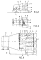
- Fig.1 und 2
- eine skizzenhafte Vorderansicht und Draufsicht einer Niederdruckturbine mitsamt Kondensator;
- Fig.3
- einen Querschnitt durch den Kondensator;
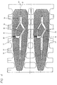
- Fig.4
- einen Querschnitt durch zwei Teilbündel.
- Beim dargestellten Wärmeaustauscher handelt es sich um einen Oberflächenkondensator in rechteckiger Bauform, wie er geeignet ist für die sogenannte "on floor"- Anordnung.
- Ueber einen Abdampfstutzen 10, mit dem der Kondensator an der Turbine angeschlossen ist, strömt der Dampf in den Kondensatorhals 1 ein. Darin wird ein möglichst gutes homogenes Strömungsfeld erzeugt, um eine saubere Dampfbespülung der stromabwärts angeordneten Bündel 2 über deren ganze Länge vorzunehmen.
- Der Kondensationsraum im Innern des Kondensatormantels beinhaltet vier getrennte Bündel 2. Dies hat unter anderem zum Ziel, dass auch während des Anlagenbetriebes eine kühlwasserseitige Teilabschaltung vorgenommen werden kann, beispielsweise zum Zwecke einer kühlwasserseitigen Inspektion eines abgeschalteten Bündels. Die unabhängige Kühlwasserbeaufschlagung kommt dadurch zum Ausdruck, dass die Wasserkammern 7 (Fig.2) durch nicht gezeigte horizontale Trennwände in Kompartimente unterteilt sind.
- Die Bündel bestehen aus einer Anzahl Rohre 5, die an ihren beiden Enden jeweils in Rohrböden 6 befestigt sind. Jenseits der Rohrböden sind jeweils die Wasserkammern 7 angeordnet. Das von den Bündeln 2 abfliessende Kondensat wird im Kondensatsammelgefäss 12 aufgefangen und gelangt von dort in den nicht dargestellten Wasser/Dampf-Kreislauf.
- Gemäss Fig.3 ist im Innern jedes Bündels 2 ein Hohlraum 13 ausgebildet, in dem sich der mit nicht kondensierbaren Gasen - nachstehend Inertgas genannt - angereicherte Dampf sammelt. In diesem Hohlraum 13 ist ein Luftkühler 14 untergebracht. Das Dampf-Inertgasgemisch durchströmt diesen Luftkühler, wobei der grösste Teil des Dampfes kondensiert. Der Rest des Gemisches wird am kalten Ende abgesaugt. Dabei ist zu beachten, dass der sich im Innern des Rohrbündels befindliche Luftkühler die Wirkung hat, dass das Dampf-Gasgemisch innerhalb des Kondensatorbündels beschleunigt wird. Dadurch verbessern sich die Verhältnisse insofern, als keine kleinen Strömungsgeschwindigkeiten vorherrschen, die den Wärmeübergang beeinträchtigen könnten.
- Ausgehend von der vorgegebenen Aussenform des Kondensators - im vorliegenden Fall eine quaderförmige Kondensatorschale -, ist die Form der vier Bündel 2 so angepasst, dass folgende Ziele erreicht werden:
- Gute Ausnützung des Temperaturgefälles
- Kleiner Druckabfall im Rohrbündel trotz hoher Packungsdichte der Berohrung
- Keine stagnierenden Inertgasansammlungen in den Dampfgassen
und den Bündeln - Keine Unterkühlung des Kondensates
- Gute Entgasung des Kondensates.
- Hierzu sind die Bündel so gestaltet, dass aller Rohre der Peripherie ohne merklichen Druckverlust gut mit Dampf angeströmt sind. Um nun eine homogene, saubere Dampfströmung zu gewährleisten und insbesondere um Stauungen innerhalb des Bündels auszuschliessen, sind die vorhandenen Strömungspfade zwischen den vier Bündeln 2 einerseits sowie zwischen den äusseren Bündeln und deren benachbarter Kondensatorwand folgendermassen ausgebildet:
- Zunächst wird vorausgesetzt, dass über dem gesamten Ausströmquerschnitt des Kondensatorhalses 1 ein einigermassen homogenes Strömungsfeld vorherrscht. Der überwiegende erste Teil des Strömungspfades zwischen Bündelanfang und Bündelende ist konvergent ausgebildet. Darin erfährt der strömende Dampf eine räumliche Beschleunigung mit entsprechender Senkung des statischen Druckes. Dies verläuft ungefähr homogen an beiden Seiten der Bündel. Bei der vorzunehmenden Kanalverengung beidseits der Bündel ist dabei der Tatsache Rechnung zu tragen, dass infolge der Kondensation der Dampfmassenstrom zunehmend geringer wird.
- Nach Erreichen der maximal vorgegebenen Geschwindigkeit wird der Dampf nunmehr bis auf die Geschwindigkeit Null abgebremst mit gleichzeitigem Druckrückgewinn. Dies wird dadurch erreicht, dass der zweite Teil des Strömungspfades divergent ausgeführt wird. Auch hier gilt es zu beachten, dass die Kanalerweiterung infolge der zunehmenden Abnahme des Massenstromes optisch nicht erkennbar sein muss. Massgebend ist, dass der zum Kondensatorboden 8 hinströmende Restdampf dort einen Staudruck erzeugt. Dadurch wird der Dampf umgelenkt und versorgt so auch die unteren Teile der Bündel. Die durch den Staudruck bedingte Temperaturerhöhung kommt dem von Rohr zu Rohr hinabfliessenden Kondensat zugute, indem es sich, falls es sich unter Sättigungstemperatur abgekühlt hatte, wieder erwärmt. Dadurch sichert man sich zwei Vorteile: Thermodynamische Verluste wegen Kondensatunterkühlung sind nicht vorhanden und der Sauerstoffgehalt des Kondensates ist auf ein Minimun reduziert.
- Als weitere Massnahme, die der gleichmässigen Bündelbeaufschlagung mit Dampf dient, wird der Luftkühler 14 im Bündelinnern auf jenem Niveau angeordnet, auf dem beidseitig der Bündel der Druckverlauf in der durchströmten Gasse ein relatives Minimum durchläuft. Im gezeigten Beispiel befindet sich der Luftkühler somit in der hinteren Hälfte der Teilbündel. Das Bündel ist so gestaltet, dass die Dampfansaugung in den Hohlraum 13 - unter Berücksichtigung des wirksamen Druckes an der Rohrperipherie und auf Grund der unterschiedlichen Rohrreihendicke - in radialer Richtung homogen über alle im Hohlraum 13 angrenzenden Rohre wirkt. Daraus resultiert ein homogener Druckgradient und damit eine eindeutige Fliessrichtung des Dampfes und der nicht kondensierbaren Gase in Richtung Luftkühler 14.
- Im Betrieb kondensiert der Dampf an den Rohren 5 und das Kondensat tropft gegen Kondensatsammelbleche 11 ab. Dieses Abtropfen erfolgt innerhalb der Bündel, wobei das Kondensat mit Dampf steigenden Druckes in Berührung kommt.
- Die gesamte Baueinheit Kondensatorschale, d.h. Gehäuse, sowie Teilbündel und Kondensatsammelbleche ist in Rohrlängsrichtung leicht um die Turbinenachse geneigt, um das rasche Abfliessen des Kondensates zu fördern.
- Wie insbesondere aus Fig. 4 ersichtlich, sind die Luftkühler innerhalb der Teilbündel von asymmetrischer Form und von aszentrischer Lage innerhalb des Hohlraumes 13. Die Bündel 2 sind bei der horizontalen Aufstellung nämlich stark asymmetrisch belastet, da die Schwerkraft und die Trägheitskraft der Dampfgeschwindigkeit nahezu senkrecht zueinander gerichtet sind. Diese Asymmetrie bezieht sich allerdings hauptsächlich auf die Kondensatbelastung im Bündel, was bezüglich der geometrischen Bündelkonturen zu einer ebenfalls asymmetrischen Lokalisierung des Druckminimums im Rohrverband führt.
- Die Lage des minimalen Druckes diktiert die Lage des Luftkühlers, da dieser der Ort der Ansammlung der nichtkondensierbaren Gase ist. Das von oben herabregnende Kondensat verstärkt den dampfseitigen Druckverlust in der unteren Bündelhälfte und verursacht damit die Verlagerung des Druckminimums nach unten. Der Luftkühler ist deshalb so konfiguriert und angeordnet, dass er der genannten Asymmetrie Rechnung trägt. Das Ansaugen der Inertgas geschieht infolge der gewählten Kühlerkonfiguration unterhalb der Längsmittellinie 22 des Bündels.
- Der Luftkühler 14 hat die Aufgabe, die nichtkondensierbaren Gase aus dem Kondensator zu entfernen. Bei diesem Vorgang sind die Dampfverluste so gering wie möglich zu halten. Dies wird dadurch erreicht, dass das Dampf/Inertgasgemisch in Richtung Absaugkanal 17 beschleunigt wird. Die hohe Geschwindigkeit hat einen guten Wärmeübergang zur Folge, was zu einer weitgehenden Kondensation des Restdampfes führt. Zwecks Beschleunigung des Gemisches wird der Querschnitt in Strömungsrichtung zunehmend kleiner bemessen, wie es aus Fig. 4 hervorgeht. Das Inertgas wird über Blenden 18 in den Kanal 17 abgesaugt. Diese Blenden, welche an der jüngsten Stelle der Kühlerabdeckung angebracht sind, stellen die physikalische Trennung des Kondensationsraumes vom Absaugkanal dar. Sie sind mehrfach über die ganze Rohrlänge verteilt und bewirken durch die Erzeugung eines Druckverlustes, dass die Saugwirkung in allen Kompartimenten des Kondensators homogen ist.
- Ein Teil der Wandung des Absaugkanals 17 ist gleichzeitig als Abdeckblech 19 konzipiert. Dieses Blech ist über die Rohre des Kühlers gestülpt und schützt diese vor der von oben nach unten fliessenden Dampf- und Kondensatströmung. Damit ist auch die Eintrittsrichtung des abzukühlenden Gemisches vorgegeben, nämlich von hinten nach vorn zu den Blenden 18 hin.
- Um das Inertgas aus dem Absaugkanal 17 zum nicht dargestellten Saugapparat zu leiten, sind eine entsprechende Anzahl Rohre 5 aus den Bündeln 2 ausgespart. Je nach Grösse und Staffelung der Rohre 5 handelt es sich dabei um das Fortlassen entweder einer oder zweier Rohrreihen. Durch diese Aussparung werden mehrere, das Bündel nach oben durchdringende Saugleitungen 20 herausgeführt. Parallel zum Bündel werden diese Saugleitungen bis zum Kondensatorboden 8 geführt, wo sie in eine zum Saugapparat führende Sammelleitung 15 münden.
- Im Bündelinnern sind stromaufwärts und stromabwärts unberohrte Ausgleichgassen 16 vorgesehen, die in den Hohlraum 13 münden. Diese Ausgleichgassen sorgen dafür, dass auch der mit Inertgas angereicherte Dampf aus dem Kern der vorderen und der hinteren Hälfte des Bündels einen reibungsfreien Weg zum Luftkühler findet. Infolge der asymmetrischen Lokalisierung des Druckminimums im Rohrverband ist hierzu die Längsmittellinie 21 dieser Restdampfgassen entsprechend unterhalb der Längsmittellinie 22 der Teilbündel angeordnet.
-
- 1
- Kondensatorhals
- 2
- Teilbündel
- 3
- Turbine
- 4
- Kondensatormantel
- 5
- Rohr
- 6
- Rohrboden
- 7
- Wasserkammer
- 8
- Kondensatorboden
- 9
- Fundament
- 10
- Abdampfstutzen
- 11
- Kondensatsammelblech
- 12
- Kondensatsammelgefäss
- 13
- Hohlraum
- 14
- Luftkühler
- 15
- Sammelleitung
- 16
- Ausgleichgasse
- 17
- Saugkanal
- 18
- Blende
- 19
- Abdeckblech
- 20
- Saugleitung
- 21
- Längsmittellinie von 16
- 22
- Längsmittellinie von 2
Claims (1)
- Dampfkondensator zur ebenerdigen Anordnung mit einer Dampfturbine,- in welchem der Dampf an kühlwasserdurchflossenen, in separaten Teilbündeln (2) zusammengefassten Rohren (5) niedergeschlagen wird, wozu die Teilbündel (2) in ihrer Längserstreckung horizontal gerichtet sind und mehrere derartige Teilbündel in der Vertikalen übereinander angeordnet sind,- wobei die in Reihen angeordneten Rohre eines Bündels einen Hohlraum (13) umschliessen, in dem ein Kühler (14) für die nicht kondensierbaren Gase angeordnet ist, und wobei durch den Kühler (14) das sich im Hohlraum (13) des Teilbündels (2) ansammelnde Gemisch von nichtkondensierbaren Gasen und Wasserdampf abgesaugt wird,- und wobei der Hohlraum (13) mit einer bündelinternen Ausgleichgasse (16) verbunden ist, die dafür sorgt, dass der mit Inertgas angereicherte Dampf aus dem Kern der vorderen und der hinteren Hälfte des Bündels dem Luftkühler zugeführt wird,dadurch gekennzeichnet,
dass die Längsmittellinie (21) der Ausgleichgasse (16) wegen der asymmetrischen Kondensatbelastung im horizontal ausgerichteten Teilbündel und der asymmetrischen Lokalisierung des Druckminimums im Rohrverband unterhalb der Längsmittellinie (22) der Teilbündel verläuft.
Applications Claiming Priority (2)
| Application Number | Priority Date | Filing Date | Title |
|---|---|---|---|
| DE19642100A DE19642100B4 (de) | 1996-10-12 | 1996-10-12 | Dampfkondensator |
| DE19642100 | 1996-10-12 |
Publications (2)
| Publication Number | Publication Date |
|---|---|
| EP0841527A2 true EP0841527A2 (de) | 1998-05-13 |
| EP0841527A3 EP0841527A3 (de) | 1998-12-02 |
Family
ID=7808547
Family Applications (1)
| Application Number | Title | Priority Date | Filing Date |
|---|---|---|---|
| EP97810703A Ceased EP0841527A3 (de) | 1996-10-12 | 1997-09-24 | Dampfkondensator |
Country Status (6)
| Country | Link |
|---|---|
| US (1) | US5941301A (de) |
| EP (1) | EP0841527A3 (de) |
| JP (1) | JP3974237B2 (de) |
| AU (1) | AU722526B2 (de) |
| DE (1) | DE19642100B4 (de) |
| HU (1) | HU221112B1 (de) |
Cited By (1)
| Publication number | Priority date | Publication date | Assignee | Title |
|---|---|---|---|---|
| WO2013117730A2 (en) | 2012-02-10 | 2013-08-15 | Alstom Technology Ltd | Water/steam cycle and method for operating the same |
Families Citing this family (8)
| Publication number | Priority date | Publication date | Assignee | Title |
|---|---|---|---|---|
| EP1039255B1 (de) | 1999-03-19 | 2003-08-27 | Alstom | Dampfkraftwerk |
| DE10016080A1 (de) * | 2000-03-31 | 2001-10-04 | Alstom Power Nv | Kondensator |
| DE10033691A1 (de) * | 2000-07-11 | 2002-01-24 | Alstom Power Nv | Kondensatorhals zwischen einer Dampfturbine und einem Kondensator |
| JP5403978B2 (ja) * | 2008-09-16 | 2014-01-29 | 三菱重工業株式会社 | 復水器 |
| JP6207957B2 (ja) * | 2013-10-04 | 2017-10-04 | 三菱重工業株式会社 | 復水器 |
| CN105793659B (zh) * | 2014-01-23 | 2018-05-01 | 三菱日立电力系统株式会社 | 冷凝器 |
| WO2017145404A1 (ja) * | 2016-02-25 | 2017-08-31 | 三菱日立パワーシステムズ株式会社 | 復水器、及びこれを備える蒸気タービンプラント |
| CN108827018B (zh) * | 2018-05-03 | 2021-04-06 | 东方电气集团东方汽轮机有限公司 | 一种适用于侧向进汽凝汽器管束结构 |
Citations (1)
| Publication number | Priority date | Publication date | Assignee | Title |
|---|---|---|---|---|
| EP0384200A1 (de) | 1989-02-23 | 1990-08-29 | Asea Brown Boveri Ag | Dampfkondensator |
Family Cites Families (8)
| Publication number | Priority date | Publication date | Assignee | Title |
|---|---|---|---|---|
| US1578031A (en) * | 1921-08-04 | 1926-03-23 | Westinghouse Electric & Mfg Co | Condenser |
| US1812591A (en) * | 1930-11-26 | 1931-06-30 | Worthington Pump & Mach Corp | Condenser |
| US2848197A (en) * | 1955-09-02 | 1958-08-19 | Lummus Co | Condenser |
| US2939685A (en) * | 1955-12-14 | 1960-06-07 | Lummus Co | Condenser deaerator |
| US2869833A (en) * | 1957-04-03 | 1959-01-20 | Worthington Corp | Modular heat exchanger |
| JPS57198984A (en) * | 1981-06-01 | 1982-12-06 | Mitsubishi Heavy Ind Ltd | Condensing apparatus |
| EP0325758B1 (de) * | 1988-01-22 | 1991-03-06 | Asea Brown Boveri Ag | Dampfkondensator |
| DE4311118A1 (de) * | 1993-04-05 | 1994-10-06 | Abb Management Ag | Dampfkondensator |
-
1996
- 1996-10-12 DE DE19642100A patent/DE19642100B4/de not_active Expired - Lifetime
-
1997
- 1997-08-12 US US08/909,736 patent/US5941301A/en not_active Expired - Lifetime
- 1997-09-24 EP EP97810703A patent/EP0841527A3/de not_active Ceased
- 1997-10-03 AU AU39921/97A patent/AU722526B2/en not_active Expired
- 1997-10-10 HU HU9701632A patent/HU221112B1/hu unknown
- 1997-10-13 JP JP27905297A patent/JP3974237B2/ja not_active Expired - Lifetime
Patent Citations (1)
| Publication number | Priority date | Publication date | Assignee | Title |
|---|---|---|---|---|
| EP0384200A1 (de) | 1989-02-23 | 1990-08-29 | Asea Brown Boveri Ag | Dampfkondensator |
Cited By (2)
| Publication number | Priority date | Publication date | Assignee | Title |
|---|---|---|---|---|
| WO2013117730A2 (en) | 2012-02-10 | 2013-08-15 | Alstom Technology Ltd | Water/steam cycle and method for operating the same |
| US9453428B2 (en) | 2012-02-10 | 2016-09-27 | Alstom Technology Ltd | Water/steam cycle and method for operating the same |
Also Published As
| Publication number | Publication date |
|---|---|
| HU221112B1 (hu) | 2002-08-28 |
| HU9701632D0 (en) | 1997-12-29 |
| DE19642100B4 (de) | 2011-09-29 |
| AU722526B2 (en) | 2000-08-03 |
| DE19642100A1 (de) | 1998-04-16 |
| HUP9701632A3 (en) | 1999-09-28 |
| EP0841527A3 (de) | 1998-12-02 |
| JP3974237B2 (ja) | 2007-09-12 |
| US5941301A (en) | 1999-08-24 |
| HUP9701632A2 (hu) | 1998-07-28 |
| JPH10170168A (ja) | 1998-06-26 |
| AU3992197A (en) | 1998-04-23 |
Similar Documents
| Publication | Publication Date | Title |
|---|---|---|
| EP0384200B1 (de) | Dampfkondensator | |
| DE69426579T2 (de) | Verdampfungswärmetauscher mit geschlossenem direktem und indirektem Kreislauf in Kombination | |
| DE69715714T2 (de) | Vorrichtung und Verfahren zum Kondensieren von Dampf | |
| DE4201637C3 (de) | Kondensator zur Verflüssigung von Dampf | |
| EP0325758B1 (de) | Dampfkondensator | |
| EP0619466B1 (de) | Dampfkondensator | |
| EP0841527A2 (de) | Dampfkondensator | |
| DE4009997A1 (de) | Verdampfer | |
| DE69802353T2 (de) | Luftgekühlter kondensator | |
| DE69605347T2 (de) | Wärmetauscher mit gelöteten Platten | |
| DE2524080C3 (de) | Wärmeübertrager, in dem ein dampfförmiges Medium unter Wärmeabgabe an ein anderes Medium kondensiert | |
| DE68913233T2 (de) | Luftgekühlter Dampfkondensator mit Vakuum. | |
| EP0795729B1 (de) | Dampfkondensator | |
| EP1139051A2 (de) | Kondensator | |
| DE19521622C2 (de) | Kondensator für kondensierbare Dämpfe | |
| DE1939245C3 (de) | Luftgekühlter Kondensator für das Kopf produkt einer Destillier- oder Rektifizier-Kolonne | |
| EP0561012B1 (de) | Verfahren und Einrichtung zum Behandeln von Wasser in einem Oberflächenkondensator | |
| EP1126227A1 (de) | Dampfkondensator | |
| DE4321250A1 (de) | Rohrbündel-Wärmetauscher | |
| DE4101031C2 (de) | Horizontal-Sprühfilmverdampfer | |
| EP0976998A1 (de) | Dampfkondensator | |
| EP0957325A1 (de) | Dampfkondensator | |
| DE3001709A1 (de) | Kopfkondensator | |
| DE1501337C (de) | Oberflachenkondensator fur Dampftur binen Abdampf | |
| DE611002C (de) | Heizkammer fuer Verdampfer und Verkocher mit senkrecht stehenden Heizrohren |
Legal Events
| Date | Code | Title | Description |
|---|---|---|---|
| PUAI | Public reference made under article 153(3) epc to a published international application that has entered the european phase |
Free format text: ORIGINAL CODE: 0009012 |
|
| AK | Designated contracting states |
Kind code of ref document: A2 Designated state(s): DE FR IT NL SE |
|
| AX | Request for extension of the european patent |
Free format text: AL;LT;LV;RO;SI |
|
| PUAL | Search report despatched |
Free format text: ORIGINAL CODE: 0009013 |
|
| AK | Designated contracting states |
Kind code of ref document: A3 Designated state(s): AT BE CH DE DK ES FI FR GB GR IE IT LI LU MC NL PT SE |
|
| AX | Request for extension of the european patent |
Free format text: AL;LT;LV;RO;SI |
|
| 17P | Request for examination filed |
Effective date: 19990317 |
|
| AKX | Designation fees paid |
Free format text: DE FR IT NL SE |
|
| 17Q | First examination report despatched |
Effective date: 20000315 |
|
| RAP1 | Party data changed (applicant data changed or rights of an application transferred) |
Owner name: ALSTOM |
|
| RAP1 | Party data changed (applicant data changed or rights of an application transferred) |
Owner name: ALSTOM (SWITZERLAND) LTD |
|
| STAA | Information on the status of an ep patent application or granted ep patent |
Free format text: STATUS: THE APPLICATION HAS BEEN REFUSED |
|
| 18R | Application refused |
Effective date: 20021003 |