EP0840016A2 - Turbomaschine, insbesondere Verdichter in Topfbauweise - Google Patents
Turbomaschine, insbesondere Verdichter in Topfbauweise Download PDFInfo
- Publication number
- EP0840016A2 EP0840016A2 EP97250306A EP97250306A EP0840016A2 EP 0840016 A2 EP0840016 A2 EP 0840016A2 EP 97250306 A EP97250306 A EP 97250306A EP 97250306 A EP97250306 A EP 97250306A EP 0840016 A2 EP0840016 A2 EP 0840016A2
- Authority
- EP
- European Patent Office
- Prior art keywords
- housing
- stator
- bundle
- bearing
- bearing block
- Prior art date
- Legal status (The legal status is an assumption and is not a legal conclusion. Google has not performed a legal analysis and makes no representation as to the accuracy of the status listed.)
- Granted
Links
- 238000007789 sealing Methods 0.000 claims description 4
- 230000008878 coupling Effects 0.000 claims 1
- 238000010168 coupling process Methods 0.000 claims 1
- 238000005859 coupling reaction Methods 0.000 claims 1
- 238000010276 construction Methods 0.000 description 3
- 238000006243 chemical reaction Methods 0.000 description 2
- 230000000903 blocking effect Effects 0.000 description 1
- 238000009434 installation Methods 0.000 description 1
- 238000004519 manufacturing process Methods 0.000 description 1
- 230000000717 retained effect Effects 0.000 description 1
Images
Classifications
-
- F—MECHANICAL ENGINEERING; LIGHTING; HEATING; WEAPONS; BLASTING
- F04—POSITIVE - DISPLACEMENT MACHINES FOR LIQUIDS; PUMPS FOR LIQUIDS OR ELASTIC FLUIDS
- F04D—NON-POSITIVE-DISPLACEMENT PUMPS
- F04D29/00—Details, component parts, or accessories
- F04D29/05—Shafts or bearings, or assemblies thereof, specially adapted for elastic fluid pumps
- F04D29/056—Bearings
-
- F—MECHANICAL ENGINEERING; LIGHTING; HEATING; WEAPONS; BLASTING
- F04—POSITIVE - DISPLACEMENT MACHINES FOR LIQUIDS; PUMPS FOR LIQUIDS OR ELASTIC FLUIDS
- F04D—NON-POSITIVE-DISPLACEMENT PUMPS
- F04D17/00—Radial-flow pumps, e.g. centrifugal pumps; Helico-centrifugal pumps
- F04D17/08—Centrifugal pumps
- F04D17/10—Centrifugal pumps for compressing or evacuating
- F04D17/12—Multi-stage pumps
- F04D17/122—Multi-stage pumps the individual rotor discs being, one for each stage, on a common shaft and axially spaced, e.g. conventional centrifugal multi- stage compressors
- F04D17/125—Multi-stage pumps the individual rotor discs being, one for each stage, on a common shaft and axially spaced, e.g. conventional centrifugal multi- stage compressors the casing being vertically split
-
- F—MECHANICAL ENGINEERING; LIGHTING; HEATING; WEAPONS; BLASTING
- F04—POSITIVE - DISPLACEMENT MACHINES FOR LIQUIDS; PUMPS FOR LIQUIDS OR ELASTIC FLUIDS
- F04D—NON-POSITIVE-DISPLACEMENT PUMPS
- F04D29/00—Details, component parts, or accessories
- F04D29/40—Casings; Connections of working fluid
- F04D29/42—Casings; Connections of working fluid for radial or helico-centrifugal pumps
- F04D29/4206—Casings; Connections of working fluid for radial or helico-centrifugal pumps especially adapted for elastic fluid pumps
Definitions
- the invention relates to a turbomachine, particularly a pot-type compressor, according to the preamble of claim 1.
- the object of the invention is to provide a turbomachine, in particular a compressor in a pot design, in which a conversion construction is possible without the problems described.
- the essence of the invention is the attachment of the bearing block to the end of the stator of the bundle protruding from the housing. It is essential to the invention that the bearing block is connected to the bundle and not to the housing. In the case of a conventional construction, the flange of the bearing block is screwed directly onto the housing.
- the arrangement according to the invention enables an exact positioning of rotor parts to stator parts outside the housing. Since the losses of a turbomachine are largely determined by the The size of the gap between the rotor and stator part are influenced, the optimal alignment between the rotor and stator part of the bundle is of crucial importance.
- the exact position assignment between the rotor and stator part can be fixed by cylindrical and / or tapered pins so that the aligned bundle can be inserted into the housing after the bearing blocks have been removed. Regardless of the position of the bundle in relation to the housing axis, the exact position assignment between the rotor and stator parts that determines the power loss is retained. This avoids possible influences on the operating behavior and operational safety of the machine due to possible deviations in the existing housing in the fit area bundle to housing and bundle to the cover.
- the existing housing and the existing cover have no influence on the position of the rotor relative to the stator parts. For this reason, it is possible to check the installation position of the rotor to the stator part without a housing. This minimizes risks when installing on site in an existing housing.
- the adapter is primarily used advantageously to compensate for the end of the stator, which in most cases has a smaller diameter and protrudes from the housing, and the flange of the bearing block, which has a larger diameter.
- the adapter can also be used to hold a seal (for example a locking labyrinth) between the bearing block and the shaft seal, which is used for gas-lubricated seals and labyrinth seals, as well as for oil-lubricated seals with a separate oil system.
- a seal for example a locking labyrinth
- the sealing gas can be connected directly to the adapter.
- the adapter can also be used to drill connection holes to seals or chambers in the stator end.
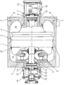
- the turbocompressor shown in the single figure has a pot-shaped housing 1.
- the area of the housing 1 on the left here is provided with a fixed contact shoulder 2.
- a cover is also possible to arrange a cover as an abutment shoulder.
- the bundle consisting of rotor 3 and stator parts 4, 5 and a shaft 6 is axially inserted into this housing 1.
- the stator part 5 of the bundle on the left comes to rest against the abutment shoulder 2.
- the end on the right side is a cover 7 which is connected to the housing 1 by screws 8.
- the respective end 9, 10 of the stator 4, 5 protrudes beyond the end of the cover 7 or the housing 1.
- an adapter 11, 12 is screwed to this end 9, 10.
- the other side of the adapter 11, 12 is connected to the respective bearing block 13, 14.
- the bearing arranged here on the left in this exemplary embodiment is designed as a radial bearing 15 and the bearing arranged on the right as a radial axial bearing 16.
- the bundle is guided in the radial direction on the one hand via the bore 17 in the abutment shoulder 2 of the housing 1 and on the other hand in the bore 18 of the cover 7.
- the bundle is guided under operating conditions through the abutment shoulder 2 in the housing 1 and by the radial axial bearing 16 arranged on the right here.
- the seal between the suction pressure 19 and the final pressure 20 in the bundle relative to the housing 1 takes place via a seal 21 arranged between the stator part 5 and the housing 1.
- the sealing gas is fed to the respective blocking labyrinth 23 via an insert 22.
Landscapes
- Engineering & Computer Science (AREA)
- Mechanical Engineering (AREA)
- General Engineering & Computer Science (AREA)
- Structures Of Non-Positive Displacement Pumps (AREA)
- Supercharger (AREA)
Abstract
Description
- Die Erfindung betrifft eine Turbomaschine, insbesondere Verdichter in Topfbauweise gemäß dem Oberbegriff des Patentanspruches 1.
- Zur Einhaltung der Betriebsparameter und zur Sicherstellung der geforderten Laufruhe / Betriebssicherheit sind bei der Konstruktion und dem Bau von Turbomaschinen hohe Toleranzanforderungen einzuhalten. Besonders bei Umbauten ohne die Möglichkeit einer Gehäusenachbearbeitung können vorhandene Fertigungsungenauigkeiten zu größeren Problemen bei der Inbetriebnahme der Maschine führen. Die geschilderte Problematik tritt insbesondere dann auf, wenn das Gehäuse eines Verdichters in der Rohrleitung eingeschweißt ist und das aus Rotor- und Statorteilen bestehende Bündel ausgetauscht werden muß.
- Aufgabe der Erfindung ist es, eine Turbomaschine, insbesondere Verdichter in Topfbauweise anzugeben, bei dem eine Umbaukonstruktion ohne die geschilderten Probleme möglich ist.
- Diese Aufgabe wird ausgehend vom Oberbegriff in Verbindung mit den kennzeichnenden Merkmalen des Patentanspruches 1 gelöst. Vorteilhafte Ausgestaltungen sind Bestandteil von Unteransprüchen.
- Kern der Erfindung ist die Befestigung des Lagerbockes am aus dem Gehäuse herausragenden stirnseitigen Ende des Stators des Bündels. Dabei ist erfindungswesentlich, daß der Lagerbock mit dem Bündel und nicht mit dem Gehäuse verbunden ist. Bei einer üblichen konventionellen Konstruktion wird der Flansch des Lagerbockes direkt an das Gehäuse angeschraubt. Die erfindungsgemäße Anordnung ermöglicht eine exakte Positionierung von Rotorteilen zu Statorteilen außerhalb des Gehäuses. Da die Verluste einer Turbomaschine maßgeblich durch die Größe der Spalte zwischen Rotor- und Statorteil beeinflußt werden, ist die optimale Ausrichtung zwischen Rotor- und Statorteil des Bündels von entscheidender Bedeutung. Nach der Ausrichtung in der Werkstatt kann die genaue Lagezuordnung zwischen Rotor- und Statorteil durch Zylinder- und/oder Kegelstifte fixiert werden, so daß nach Abbau der Lagerböcke das ausgerichtete Bündel in das Gehäuse eingeschoben werden kann. Unabhängig von der Lagepositionierung des Bündels zur Gehäuseachse bleibt die eingestellte und die Verlustleistung bestimmende genaue Lagezuordnung zwischen Rotor- und Statorteil erhalten. Dadurch werden mögliche Einflüsse auf das Betriebsverhalten und die Betriebssicherheit der Maschine durch eventuelle Abweichungen in dem vorhandenen Gehäuse im Passungsbereich Bündel zum Gehäuse und Bündel zum Deckel vermieden.
- Mit der vorgeschlagenen konstruktiven Ausführung hat das vorhandene Gehäuse und der vorhandene Deckel keinen Einfluß auf die Lage des Rotors zu den Statorteilen. Aus diesem Grunde ist es möglich, ohne Gehäuse eine Überprüfung der Einbaulage Rotor zu Statorteil vorzunehmen. Dadurch werden Risiken bei der Montage auf der Baustelle in ein vorhandenes Gehäuse minimiert.
- Je nach den Durchmesserverhältnissen zwischen dem stirnseitigen Statorende und dem dazugehörigen Lagerbock kann es zweckmäßig sein, einen Adapter dazwischenzusetzen. Der Adapter wird in erster Linie vorteilhaft dazu genutzt, um einen Ausgleich zu dem in den meisten Fällen einen kleineren Durchmesser aufweisenden aus dem Gehäuse herausragenden Ende des Stators und dem einen größeren Durchmesser aufweisenden Flansch des Lagerbockes zu schaffen.
- Der Adapter kann auch zur Aufnahme einer Dichtung (beispielsweise Sperrlabyrinth) zwischen Lagerbock und Wellendichtung genutzt werden, die bei gasgeschmierten Dichtungen und Labyrinthdichtungen, sowie bei ölgeschmierten Dichtungen mit getrenntem Ölsystem, d. h. Lageröl und Dichtungsöl sind getrennt, erforderlich ist. Der Anschluß des Sperrgases kann dabei direkt am Adapter erfolgen. Der Adapter kann auch zum Durchführen von Anschlußbohrungen zu Dichtungen oder Kammern im Statorende genutzt werden.
- In der einzigen Figur wird anhand eines Ausführungsbeispieles im Längsschnitt die erfindungsgemäße Konstruktion näher erläutert.
- Der in der einzigen Figur dargestellte Turboverdichter weist ein Gehäuse 1 in Topfbauweise auf. In diesem Ausführungsbeispiel ist der hier links liegende Bereich des Gehäuses 1 mit einer festen Anlageschulter 2 versehen. Alternativ ist auch die Anordnung eines Deckels als Anlageschulter möglich. In dieses Gehäuse 1 wird das aus Rotor- 3 und Statorteilen 4, 5 sowie einer Welle 6 bestehende Bündel axial eingeschoben. Dabei kommt das links sich befindende Statorteil 5 des Bündels an der Anlageschulter 2 zur Anlage. Den Abschluß auf der rechten Seite bildet ein Deckel 7, der über Schrauben 8 mit dem Gehäuse 1 verbunden ist. Das jeweilige stirnseitige Ende 9, 10 des Stators 4, 5 ragt über den stirnseitigen Abschluß des Deckels 7 bzw. des Gehäuses 1 hinaus. In diesem Ausführungsbeispiel ist an dieses Ende 9, 10 ein Adapter 11, 12 angeschraubt. Die andere Seite des Adapters 11, 12 ist mit dem jeweiligen Lagerbock 13, 14 verbunden. Das in diesem Ausführungsbeispiel hier links angeordnete Lager ist als Radiallager 15 und das rechts angeordnete Lager als Radial-Axiallager 16 ausgebildet. Die Führung des Bündels in radialer Richtung erfolgt zum einen über die Bohrung 17 in der Anlageschulter 2 des Gehäuses 1 und zum anderen in der Bohrung 18 des Deckels 7. In axialer Richtung erfolgt die Führung des Bündels unter Betriebsbedingungen durch die Anlageschulter 2 im Gehäuse 1 und durch das hier rechts angeordnete Radial-Axiallager 16. Die Abdichtung zwischen Saugdruck 19 und Enddruck 20 im Bündel zum Gehäuse 1 erfolgt über eine zwischen dem Statorteil 5 und dem Gehäuse 1 angeordnete Dichtung 21. In diesem Ausführungsbeispiel ist in beiden Adaptern 11, 12 ein Sperrlabyrinth 23 als Dichtung zwischen Lagerbock 13, 14 und Wellendichtung angeordnet. Das Sperrgas wird dabei über einen Einsatz 22 dem jeweiligen Sperrlabyrinth 23 zugeführt.
Claims (5)
- Turbomaschine, insbesondere Verdichter in Topfbauweise mit einem eine Anlageschulter aufweisenden Gehäuse, einem darin einschiebbaren aus Rotor- und Statorteilen bestehenden Bündel und einem das Gehäuse auf einer Seite abschließenden Deckel sowie einer die Rotorteile tragenden Welle, deren aus dem Gehäuse nach rechts und nach links sich erstreckende Zapfen in je einem Lagerbock mittels eines Radiallagers und eines Radial-Axiallagers gelagert sind und ein Zapfenende mit einem Kupplungselement zum Anschluß für den Antrieb der Turbomaschine versehen ist, wobei die Führung des Bündels in radialer Richtung durch eine im Bereich der Anlageschulter des Gehäuses angebrachte Bohrung und eine im Deckel angebrachte Bohrung und in axialer Richtung unter Betriebsbedingungen durch die Anlageschulter im Gehäuse und durch das Radial-Axiallager erfolgt,
dadurch gekennzeichnet,
daß der jeweilige Lagerbock (13, 14) am jeweiligen aus dem Gehäuse (1) herausragenden stirnseitigen Ende des Stators (4, 5) des Bündels befestigt ist. - Turbomaschine nach Anspruch 1,
dadurch gekennzeichnet,
daß zwischen dem jeweiligen aus dem Gehäuse (1) herausragenden stirnseitigen Ende des Stators (4, 5) des Bündels und dem jeweiligen Lagerbock (13, 14) ein Adapter (11, 12) angeordnet ist. - Turbomaschine nach Anspruch 2,
dadurch gekennzeichnet,
daß der Adapter (11, 12) zum Ausgleich des einen kleineren Durchmesser aufweisenden Statorendes und des einen größeren Durchmesser aufweisenden Lagerbockes (13, 14) eingesetzt wird. - Turbomaschine nach den Ansprüchen 2 und 3,
dadurch gekennzeichnet,
daß der Adapter (11, 12) in einem Gehäusering einen darin angeordneten Einsatz (22) mit einem Sperrlabyrinth (23) aufweist, das zur Trennung von Lagerbock (13, 14) und Wellendichtung mit Sperrgas beaufschlagbar ist. - Turbomaschine nach einem der Ansprüche 2 - 4,
dadurch gekennzeichnet,
daß der Adapter (11, 12) Anschlußbohrungen zu Dichtungen oder Kammern im Statorende aufweist.
Applications Claiming Priority (4)
| Application Number | Priority Date | Filing Date | Title |
|---|---|---|---|
| DE19646528 | 1996-10-29 | ||
| DE19646528 | 1996-10-29 | ||
| DE19745606A DE19745606C2 (de) | 1996-10-29 | 1997-10-08 | Turbomaschine, insbesondere Verdichter in Topfbauweise |
| DE19745606 | 1997-10-08 |
Publications (3)
| Publication Number | Publication Date |
|---|---|
| EP0840016A2 true EP0840016A2 (de) | 1998-05-06 |
| EP0840016A3 EP0840016A3 (de) | 1999-01-13 |
| EP0840016B1 EP0840016B1 (de) | 2003-02-05 |
Family
ID=26031186
Family Applications (1)
| Application Number | Title | Priority Date | Filing Date |
|---|---|---|---|
| EP19970250306 Expired - Lifetime EP0840016B1 (de) | 1996-10-29 | 1997-10-16 | Turbomaschine, insbesondere Verdichter in Topfbauweise |
Country Status (2)
| Country | Link |
|---|---|
| EP (1) | EP0840016B1 (de) |
| RU (1) | RU2140578C1 (de) |
Cited By (5)
| Publication number | Priority date | Publication date | Assignee | Title |
|---|---|---|---|---|
| WO2015128144A1 (de) * | 2014-02-26 | 2015-09-03 | Siemens Aktiengesellschaft | Gehäuse einer fluidenergiemaschine |
| CN106232993A (zh) * | 2014-04-17 | 2016-12-14 | 西门子公司 | 具有端侧的盖的装置 |
| US10001143B2 (en) | 2013-02-26 | 2018-06-19 | Mitsubishi Heavy Industries Compressor Corporation | Method for assembling compressor, and bundle guide device |
| CN109469646A (zh) * | 2018-10-22 | 2019-03-15 | 沈阳透平机械股份有限公司 | 空分机壳结构 |
| US10233945B2 (en) | 2013-02-27 | 2019-03-19 | Mitsubishi Heavy Industries Compressor Corporation | Compressor assembly method, and bundle guiding device |
Families Citing this family (21)
| Publication number | Priority date | Publication date | Assignee | Title |
|---|---|---|---|---|
| RU2175412C1 (ru) * | 2000-02-03 | 2001-10-27 | Открытое акционерное общество "Авиадвигатель" | Поворотный направляющий аппарат компрессора |
| ITMI20011961A1 (it) * | 2001-09-20 | 2003-03-20 | Nuovo Pignone Spa | Flangia migliorata di accoppiamento tra compressore assiale e gruppo di dischi rotorici di alta pressione in una turbina a gas |
| FR2837240B1 (fr) * | 2002-03-14 | 2004-07-09 | Snecma Moteurs | Dispositif de support et de recentrage d'un arbre d'une soufflante d'un turboreacteur apres decouplage |
| RU2225538C2 (ru) * | 2002-05-30 | 2004-03-10 | Открытое акционерное общество "Авиадвигатель" | Компрессор газотурбинного двигателя |
| RU2235922C2 (ru) * | 2002-08-20 | 2004-09-10 | Открытое акционерное общество "Авиадвигатель" | Компрессор газотурбинного двигателя |
| FR2846379B1 (fr) * | 2002-10-23 | 2005-01-21 | Snecma Moteurs | Systeme de decouplage par charge explosive d'une soufflante d'un turboreacteur |
| RU2243419C2 (ru) * | 2003-02-11 | 2004-12-27 | Открытое акционерное общество "Авиадвигатель" | Высоконапорный компрессор газотурбинного двигателя |
| RU2261373C2 (ru) * | 2003-05-26 | 2005-09-27 | Открытое акционерное общество "Авиадвигатель" | Обогреваемый поворотный направляющий аппарат компрессора |
| RU2257493C2 (ru) * | 2003-05-28 | 2005-07-27 | Открытое акционерное общество "Авиадвигатель" | Компрессор газотурбинного двигателя |
| RU2266437C1 (ru) * | 2004-03-09 | 2005-12-20 | Открытое акционерное общество Научно-производственное объединение "Искра" | Способ сборки центробежного нагнетателя |
| RU2267656C2 (ru) * | 2004-03-25 | 2006-01-10 | Открытое акционерное общество "Авиадвигатель" | Осевой компрессор турбомашины |
| RU2282758C2 (ru) * | 2004-12-16 | 2006-08-27 | Открытое акционерное общество "Научно-производственное объединение "Сатурн" (ОАО "НПО "Сатурн") | Узел соединения роторов компрессора и турбины газотурбинного двигателя |
| FR2884568B1 (fr) * | 2005-04-15 | 2007-06-08 | Snecma Moteurs Sa | Agencement d'assemblage entre une bague interieure de palier et un tourillon, bague et tourillon adaptes a un tel agencement, et turbomachine equipee de ceux-ci |
| RU2295657C1 (ru) * | 2005-09-08 | 2007-03-20 | Открытое акционерное общество Научно-производственное объединение "Искра" | Устройство для соединения частей и узлов в агрегатах |
| RU2311565C1 (ru) * | 2006-04-13 | 2007-11-27 | Открытое акционерное общество "Авиадвигатель" | Высоконапорный компрессор газотурбинного двигателя |
| RU2315207C1 (ru) * | 2006-05-03 | 2008-01-20 | Закрытое акционерное общество "Научно-исследовательский и конструкторский институт центробежных и роторных компрессоров им. В.Б. Шнеппа" | Корпус сжатия на опорной раме |
| RU2407920C1 (ru) * | 2009-08-05 | 2010-12-27 | Закрытое акционерное общество "Научно-исследовательский и конструкторский институт центробежных и роторных компрессоров им. В.Б. Шнеппа" | Корпус компрессора на опорной раме |
| RU2430276C1 (ru) * | 2010-04-21 | 2011-09-27 | Открытое акционерное общество "Авиадвигатель" | Компрессор газотурбинного двигателя |
| US9062690B2 (en) * | 2010-11-30 | 2015-06-23 | General Electric Company | Carbon dioxide compression systems |
| ITCO20110027A1 (it) * | 2011-07-21 | 2013-01-22 | Nuovo Pignone Spa | Turbomacchina centrifuga multistadio |
| RU178534U1 (ru) * | 2017-02-02 | 2018-04-06 | Федеральное государственное бюджетное образовательное учреждение высшего образования "Самарский государственный университет путей сообщения" (СамГУПС) | Турбокомпрессор |
Family Cites Families (9)
| Publication number | Priority date | Publication date | Assignee | Title |
|---|---|---|---|---|
| CH529926A (de) * | 1971-02-24 | 1972-10-31 | Nevsky Mashinostroitelny Zd Im | Zentrifugale Strömungsmaschine, insbesondere Hochdruckverdichter |
| US4098558A (en) * | 1976-08-23 | 1978-07-04 | Worthington Pump, Inc. | Preassembled unit or cartridge for multi-stage barrel type centrifugal pumps |
| CH640608A5 (en) * | 1979-09-07 | 1984-01-13 | Sulzer Ag | Centrifugal pump having a double-entry, bispiral casing and an axially removable inner block |
| SU1373885A1 (ru) * | 1983-04-27 | 1988-02-15 | Производственное объединение "Невский завод" им.В.И.Ленина | Центробежный нагнетатель |
| WO1987005080A1 (en) * | 1986-02-20 | 1987-08-27 | Proizvodstvennoe Obiedinenie "Nevsky Zavod" Imeni | Centrifugal compressor |
| CH669979A5 (de) * | 1986-04-30 | 1989-04-28 | Sulzer Ag | |
| CH684495A5 (de) * | 1991-09-04 | 1994-09-30 | Escher Wyss Ag | Turbomaschine. |
| RU2037054C1 (ru) * | 1992-03-26 | 1995-06-09 | Научно-Производственное Объединение По Исследованию И Проектированию Энергетического Оборудования Им.И.И.Ползунова | Опора корпуса турбомашины |
| JPH0988864A (ja) * | 1995-09-26 | 1997-03-31 | Ebara Corp | 二重胴型高圧多段ポンプの構造 |
-
1997
- 1997-10-16 EP EP19970250306 patent/EP0840016B1/de not_active Expired - Lifetime
- 1997-10-28 RU RU97117603A patent/RU2140578C1/ru not_active IP Right Cessation
Non-Patent Citations (1)
| Title |
|---|
| None |
Cited By (8)
| Publication number | Priority date | Publication date | Assignee | Title |
|---|---|---|---|---|
| US10001143B2 (en) | 2013-02-26 | 2018-06-19 | Mitsubishi Heavy Industries Compressor Corporation | Method for assembling compressor, and bundle guide device |
| US10233945B2 (en) | 2013-02-27 | 2019-03-19 | Mitsubishi Heavy Industries Compressor Corporation | Compressor assembly method, and bundle guiding device |
| WO2015128144A1 (de) * | 2014-02-26 | 2015-09-03 | Siemens Aktiengesellschaft | Gehäuse einer fluidenergiemaschine |
| CN106062377A (zh) * | 2014-02-26 | 2016-10-26 | 西门子公司 | 流体能量机器的壳体 |
| US10208761B2 (en) | 2014-02-26 | 2019-02-19 | Siemens Aktiengesellschaft | Housing of a fluid energy machine |
| CN106232993A (zh) * | 2014-04-17 | 2016-12-14 | 西门子公司 | 具有端侧的盖的装置 |
| CN109469646A (zh) * | 2018-10-22 | 2019-03-15 | 沈阳透平机械股份有限公司 | 空分机壳结构 |
| CN109469646B (zh) * | 2018-10-22 | 2021-06-11 | 沈阳透平机械股份有限公司 | 空分机壳结构 |
Also Published As
| Publication number | Publication date |
|---|---|
| RU2140578C1 (ru) | 1999-10-27 |
| EP0840016A3 (de) | 1999-01-13 |
| EP0840016B1 (de) | 2003-02-05 |
Similar Documents
| Publication | Publication Date | Title |
|---|---|---|
| EP0840016A2 (de) | Turbomaschine, insbesondere Verdichter in Topfbauweise | |
| DE68908244T2 (de) | Lagerdämpfungsbuchse für einen Turbolader. | |
| DE69111691T2 (de) | Geteilte Gleitringdichtung. | |
| DE4331560B4 (de) | Magnetisch gekuppelte Kreiselpumpe | |
| EP2652347B1 (de) | Elektrische maschine, insbesondere eines pumpenaggregates | |
| DE102009003714B4 (de) | Turbinenstatorschaufelhaltesystem und -verfahren | |
| DE602004002049T2 (de) | Niederdruck-Turbine einer Turbomaschine | |
| EP2665953B1 (de) | Wellendichtungsanordnung | |
| DE102007001388A1 (de) | Elektrowerkzeug und Verfahren zum Zusammenbauen desselben | |
| EP2994644A1 (de) | Pumpenanordnung mit einer gleitlageranordnung | |
| DE60207675T2 (de) | Gleitringdichtung | |
| CH686093A5 (de) | Radiallager. | |
| EP3203035A1 (de) | Leitschaufelsystem für eine strömungsmaschine | |
| EP2558726A2 (de) | Verdichterflansch für schraubenverdichter | |
| DE102015104438B4 (de) | Vakuumsystem | |
| DE19745606C2 (de) | Turbomaschine, insbesondere Verdichter in Topfbauweise | |
| DE19750920A1 (de) | Getriebekopfanordnung und Verfahren zur Montage derselben an einen Motor | |
| DE102022106059B3 (de) | Flachdichtung und elektrische Rotationsmaschine | |
| DE10332010B4 (de) | Drehdurchführung | |
| DE19961567A1 (de) | Hydraulische Vorrichtung zur stufenlos variablen Nockenwellenverstellung | |
| EP3599387B1 (de) | Ladeeinrichtung | |
| CH662865A5 (de) | Topfgehaeuse fuer eine kreiselpumpe. | |
| EP4259935B1 (de) | Pumpenvorrichtung für ein hydraulisches system eines kraftfahrzeugs, hydraulisches system | |
| EP2897258A1 (de) | Einstellbare Fixierung einer Hülse auf der Welle einer dynamoelektrischen Maschine | |
| DE102024103690B3 (de) | Lageranordnung zur Lagerung einer Abgasturboladerwelle eines Abgasturboladers |
Legal Events
| Date | Code | Title | Description |
|---|---|---|---|
| PUAI | Public reference made under article 153(3) epc to a published international application that has entered the european phase |
Free format text: ORIGINAL CODE: 0009012 |
|
| AK | Designated contracting states |
Kind code of ref document: A2 Designated state(s): CH DE FR GB IT LI NL |
|
| PUAL | Search report despatched |
Free format text: ORIGINAL CODE: 0009013 |
|
| AK | Designated contracting states |
Kind code of ref document: A3 Designated state(s): AT BE CH DE DK ES FI FR GB GR IE IT LI LU MC NL PT SE |
|
| 17P | Request for examination filed |
Effective date: 19990108 |
|
| AKX | Designation fees paid |
Free format text: CH DE FR GB IT LI NL |
|
| 17Q | First examination report despatched |
Effective date: 20020115 |
|
| GRAG | Despatch of communication of intention to grant |
Free format text: ORIGINAL CODE: EPIDOS AGRA |
|
| GRAG | Despatch of communication of intention to grant |
Free format text: ORIGINAL CODE: EPIDOS AGRA |
|
| GRAH | Despatch of communication of intention to grant a patent |
Free format text: ORIGINAL CODE: EPIDOS IGRA |
|
| RAP1 | Party data changed (applicant data changed or rights of an application transferred) |
Owner name: SIEMENS AKTIENGESELLSCHAFT |
|
| GRAH | Despatch of communication of intention to grant a patent |
Free format text: ORIGINAL CODE: EPIDOS IGRA |
|
| GRAA | (expected) grant |
Free format text: ORIGINAL CODE: 0009210 |
|
| AK | Designated contracting states |
Designated state(s): CH DE FR GB IT LI NL |
|
| REG | Reference to a national code |
Ref country code: GB Ref legal event code: FG4D Free format text: NOT ENGLISH |
|
| REG | Reference to a national code |
Ref country code: CH Ref legal event code: NV Representative=s name: SIEMENS SCHWEIZ AG Ref country code: CH Ref legal event code: EP |
|
| REF | Corresponds to: |
Ref document number: 59709261 Country of ref document: DE Date of ref document: 20030313 Kind code of ref document: P |
|
| GBT | Gb: translation of ep patent filed (gb section 77(6)(a)/1977) |
Effective date: 20030501 |
|
| ET | Fr: translation filed | ||
| PLBE | No opposition filed within time limit |
Free format text: ORIGINAL CODE: 0009261 |
|
| STAA | Information on the status of an ep patent application or granted ep patent |
Free format text: STATUS: NO OPPOSITION FILED WITHIN TIME LIMIT |
|
| 26N | No opposition filed |
Effective date: 20031106 |
|
| REG | Reference to a national code |
Ref country code: CH Ref legal event code: PCAR Free format text: SIEMENS SCHWEIZ AG;INTELLECTUAL PROPERTY FREILAGERSTRASSE 40;8047 ZUERICH (CH) |
|
| PGFP | Annual fee paid to national office [announced via postgrant information from national office to epo] |
Ref country code: FR Payment date: 20121031 Year of fee payment: 16 |
|
| PGFP | Annual fee paid to national office [announced via postgrant information from national office to epo] |
Ref country code: IT Payment date: 20121030 Year of fee payment: 16 Ref country code: GB Payment date: 20121011 Year of fee payment: 16 |
|
| PGFP | Annual fee paid to national office [announced via postgrant information from national office to epo] |
Ref country code: NL Payment date: 20121009 Year of fee payment: 16 |
|
| PGFP | Annual fee paid to national office [announced via postgrant information from national office to epo] |
Ref country code: CH Payment date: 20130110 Year of fee payment: 16 Ref country code: DE Payment date: 20121216 Year of fee payment: 16 |
|
| REG | Reference to a national code |
Ref country code: NL Ref legal event code: V1 Effective date: 20140501 |
|
| REG | Reference to a national code |
Ref country code: CH Ref legal event code: PL |
|
| GBPC | Gb: european patent ceased through non-payment of renewal fee |
Effective date: 20131016 |
|
| PG25 | Lapsed in a contracting state [announced via postgrant information from national office to epo] |
Ref country code: CH Free format text: LAPSE BECAUSE OF NON-PAYMENT OF DUE FEES Effective date: 20131031 Ref country code: LI Free format text: LAPSE BECAUSE OF NON-PAYMENT OF DUE FEES Effective date: 20131031 Ref country code: GB Free format text: LAPSE BECAUSE OF NON-PAYMENT OF DUE FEES Effective date: 20131016 |
|
| REG | Reference to a national code |
Ref country code: FR Ref legal event code: ST Effective date: 20140630 |
|
| REG | Reference to a national code |
Ref country code: DE Ref legal event code: R119 Ref document number: 59709261 Country of ref document: DE Effective date: 20140501 |
|
| PG25 | Lapsed in a contracting state [announced via postgrant information from national office to epo] |
Ref country code: NL Free format text: LAPSE BECAUSE OF NON-PAYMENT OF DUE FEES Effective date: 20140501 Ref country code: FR Free format text: LAPSE BECAUSE OF NON-PAYMENT OF DUE FEES Effective date: 20131031 Ref country code: DE Free format text: LAPSE BECAUSE OF NON-PAYMENT OF DUE FEES Effective date: 20140501 Ref country code: IT Free format text: LAPSE BECAUSE OF NON-PAYMENT OF DUE FEES Effective date: 20131016 |