EP0838652A2 - Wärmetauscher - Google Patents
Wärmetauscher Download PDFInfo
- Publication number
- EP0838652A2 EP0838652A2 EP97118461A EP97118461A EP0838652A2 EP 0838652 A2 EP0838652 A2 EP 0838652A2 EP 97118461 A EP97118461 A EP 97118461A EP 97118461 A EP97118461 A EP 97118461A EP 0838652 A2 EP0838652 A2 EP 0838652A2
- Authority
- EP
- European Patent Office
- Prior art keywords
- tank
- base plate
- heat exchanger
- folded
- metal plate
- Prior art date
- Legal status (The legal status is an assumption and is not a legal conclusion. Google has not performed a legal analysis and makes no representation as to the accuracy of the status listed.)
- Granted
Links
- 229910052751 metal Inorganic materials 0.000 claims description 29
- 239000002184 metal Substances 0.000 claims description 29
- 238000005219 brazing Methods 0.000 claims description 14
- 238000000034 method Methods 0.000 claims description 9
- 210000000078 claw Anatomy 0.000 claims description 7
- 238000005520 cutting process Methods 0.000 claims description 3
- 238000004519 manufacturing process Methods 0.000 claims description 3
- 239000011162 core material Substances 0.000 description 7
- 239000000463 material Substances 0.000 description 6
- 229910052782 aluminium Inorganic materials 0.000 description 3
- XAGFODPZIPBFFR-UHFFFAOYSA-N aluminium Chemical compound [Al] XAGFODPZIPBFFR-UHFFFAOYSA-N 0.000 description 3
- 239000010953 base metal Substances 0.000 description 2
- 239000000498 cooling water Substances 0.000 description 2
- 238000012986 modification Methods 0.000 description 2
- 230000004048 modification Effects 0.000 description 2
- 238000003825 pressing Methods 0.000 description 2
- XLYOFNOQVPJJNP-UHFFFAOYSA-N water Substances O XLYOFNOQVPJJNP-UHFFFAOYSA-N 0.000 description 2
- 238000004378 air conditioning Methods 0.000 description 1
- AZDRQVAHHNSJOQ-UHFFFAOYSA-N alumane Chemical group [AlH3] AZDRQVAHHNSJOQ-UHFFFAOYSA-N 0.000 description 1
- 230000003247 decreasing effect Effects 0.000 description 1
- 238000010409 ironing Methods 0.000 description 1
- 230000002093 peripheral effect Effects 0.000 description 1
Images


Classifications
-
- F—MECHANICAL ENGINEERING; LIGHTING; HEATING; WEAPONS; BLASTING
- F28—HEAT EXCHANGE IN GENERAL
- F28F—DETAILS OF HEAT-EXCHANGE AND HEAT-TRANSFER APPARATUS, OF GENERAL APPLICATION
- F28F9/00—Casings; Header boxes; Auxiliary supports for elements; Auxiliary members within casings
-
- F—MECHANICAL ENGINEERING; LIGHTING; HEATING; WEAPONS; BLASTING
- F28—HEAT EXCHANGE IN GENERAL
- F28F—DETAILS OF HEAT-EXCHANGE AND HEAT-TRANSFER APPARATUS, OF GENERAL APPLICATION
- F28F9/00—Casings; Header boxes; Auxiliary supports for elements; Auxiliary members within casings
- F28F9/02—Header boxes; End plates
- F28F9/0219—Arrangements for sealing end plates into casing or header box; Header box sub-elements
- F28F9/0224—Header boxes formed by sealing end plates into covers
Definitions
- the present invention relates to a heat exchanger which is preferably used for a heater core or the like for an automotive air conditioning device, and more particularly relative to a tank and a base plate connected to the tank.
- the heat exchanger includes a tank 1 and base plate 2 as shown in FIG. 10.
- unfolded metal plates are respectively folded and the folded portions are connected to each other to form the tank 1 and the base plate 2.
- connection surfaces are formed at folded portions of the tank 1 to ensure a connection area to be brazed.
- a claw portion 3 for receiving an insert plate for holding a core portion of the heat exchanger is provided on a folded portion of the base plate 2 in lateral direction (i.e., a short side portion) as shown in FIG. 10. Since a brazing material is clad on the core portion before brazing, the insert plate may extend outwardly in a longitudinal direction of the base plate so that the claw portion 3 may extend outwardly in the longitudinal direction of the base plate. Therefore, the folded portion of the base plate in the lateral direction also extends outwardly in the longitudinal direction of the base plate 2 so that the clearance 51 shown in FIG. 11 is further enlarged. Thus, the tank 1 and the base plate 2 cannot be securely connected and brazed to each other.
- a protrusion protrudes from an inner wall of the base plate to be opposite to a connection portion between folded portions of the tank. Therefore, a clearance formed between an outside of the connection portion of the folded portions of the tank and an inside of the base plate is greatly decreased to securely braze a joined portion between the tube and base plate.
- a rib for increasing stiffness of the base plate in a longitudinal direction is provided in a claw portion formed on a folded portion of the base plate in the lateral direction. Therefore, even if a force extending outwardly in a longitudinal direction of the base plate is applied to the base plate before brazing, the folded portion of the base plate is not bent outwardly by forming the rib. Thus, the clearance between the tube and the base plate is not enlarged in assembling process of the heat exchanger, and a brazing between the tube and the base plate can be securely performed.
- a heat exchanger includes a tank 1 formed in a U-shape in a cross-section thereof and a base plate 2 connected to an opening end portion of the tank 1.
- the base plate 2 is also formed in a U-shape in a cross-section thereof.
- a plurality of tube receiving holes 4 are provided on the base plate 2 in such a manner that a longitudinal direction of the flat holes 4 for receiving the tubes is parallel to a lateral direction of the base plate 2.
- a cross-section of a flat tube 5 is formed in a flat shape, and each end portion of the flat tube 5 is inserted into and joined with the tube receiving holes 4 of the base plate 2.
- a plurality of corrugated fins 6 are formed in a wavy shape and are disposed between the flat tubes 5 to be joined with the flat tubes 5.
- Both insert plates 7 are respectively disposed at both side portions of a core portion (i.e., heat exchanging portion) having the flat tubes 5 and the corrugated fins 6 and are connected to the base plates 2 and the corrugated fins 7.
- An inlet pipe 8 for warm water e.g., engine cooling water
- An outlet pipe 9 for cooled water e.g., engine cooling water
- a structure of the heat exchanger in FIG. 1 is a symmetrical structure with respective to the left and right direction, the positions of inlet pipe 8 and the outlet pipe 9 may be changed.
- the heater core shown in FIG.1 is structured by an aluminum heat exchanger integrally connected by brazing.
- the corrugated fins 6, the inlet pipe 8 and the outlet pipe 9 are made of aluminum bare material in which a brazing material is not clad, other materials (1, 2, 5 and 7) are made of an aluminum clad material in which a brazing material is clad at both sides of the aluminum core material.
- FIG. 2 shows an unfolded state of a metal plate forming the tank 1.
- An unfolded metal plate 13 has a rectangular body portion 13a, and first folded portions 13f are formed in the body portion 13 along a long side portion thereof. Further, second folded portions 13b protruding from short side portions of the body portion 13a are formed. A plurality of semicircular protrusions 13c are formed proximate to long ends of body portion 13a. Connection surfaces 13d for ensuring brazing by increasing a connection area to be brazed are formed at both outer edge portions formed in a vertical direction of the second folded portions 13b.
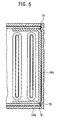
- the unfolded metal plate 13 for the tank 1 is formed in a tank shape shown FIG. 3, that is, a tank shape (i.e., box shape) having a U-shaped cross section.
- a tank shape i.e., box shape
- FIGS. 2 and 3 by folding the first and second folded portions 13f and 13b and the connection surface 13d at a ridgeline 13e shown with dotted lines in FIG. 2, the tank where one end side is opened and another end side is closed is formed.
- connection surfaces 13d of the second folded portions 13b contact inner surfaces of the first folded portions 13f to increase the brazing area therebetween. Therefore, the ridgeline 13e of the first folded portion 13f is offset outwardly from the ridgeline 13e of the connection surface 13d by a plate thickness d1 of the unfolded metal plate 13.
- an unfolded metal plate 14 for the base plate has the same shape as the unfolded metal plate 13 for the tank.
- the unfolded metal plate 14 includes a rectangular body portion 14a, first folded portions 14b and second folded portions.
- the first folded portions 14b are formed along a long side portion of the body portion 14a, and the second folded portions 14c are formed to protrude from short side portions of the body portion 14a.
- a plurality of semicircular concave portions are formed on the first folded portions 14b of the body portion 14a to correspond to the semicircular protrusions 13c of the unfolded metal plate 13.
- a dotted line 14e illustrates a ridgeline as a folding position of the first and second folded portions 14b and 14c. End portions in the longitudinal direction of the second folded portion 14c are offset outwardly from the dotted line 14e of the first folded portions 14b by a plate thickness d2 of the unfolded metal plate 14. Therefore, after folding the first and the second folded portions 14b and 14c, the second folded portions 14c can be folded on end surfaces of the first folded portions (see FIG. 3). Thus, the second folded portions 14c can be securely brazed on the end surfaces of the first folded portions 14b.
- the first and second folded portions 14b and 14c are folded along the dotted line 14c so that the metal plate 14 is formed in a shape shown in FIG. 3, i.e., a box shape in which one end side is closed and another end side is opened. Since the second folded portions 14c are folded on the end surfaces of the first folded portions 14b, a brazing area between the first and second folded portions 14b and 14c is increased to sufficiently braze therebetween.
- the tank 1 and the base plate 2 are assembled in such a manner that the first and second folded portions 13f and 13b of the tank are inserted into inner peripheral sides of the first and second folded portions 14b and 14c of the base plate 2.
- the semicircular protrusions 13c of the tank 1 into the semicircular concave portions 14c of the base plate 2
- an assembled state of the tank 1 and the base plate 2 can be maintained to prevent the tank 1 and the base plate 2 from being separated after being assembled together.
- protrusion portions 15 are formed inside the second folded portions 14c of the base plate 2, and the protrusion portions 15 protrude from the second folded portions 14c of the base plate 2 to be opposite to a position where the first and second folded portions 13f and 13b are connected to each other.
- the protrusion portions 15 are formed by an ironing process at the same time as the folding step of the base plate 2.
- clearances formed at connection portions between the first and second folded portions 13f and 13b of the tank 1 are filled. Therefore, a brazing between the tank 1 and the base metal 2 can be securely performed.
- the second folded portion 14 of the base plate 2 is formed by the ribs 16, a rigidity of the base plate 2 in the longitudinal direction thereof can be improved. Even if the insert plate 7 is inserted into the claw portions 3 so that the insert plate 7 extends outwardly in the longitudinal direction of the tube 1 before brazing, the second folded portion 14c of the base plate 2 is not bent outwardly by forming the ribs 16 due to the concave portions. Thus, in this embodiment, the clearances 51 (see FIG. 11) formed at a connection portion between the first and second folded portions 13f and 13b of the tank 1 is not further enlarged. Therefore, a brazing between the tank 1 and the base metal 2 can be securely performed.
- the ribs 16 due to the concave portions are formed by a coining process or a press process in an unfolded metal plate before folding the base plate 2.
- the craw portions 3 for receiving the insert plate 7 are formed on the second folded portion 14 of the base plate 2, and a concave portion 18 is formed in each craw portion 3.
- the concave portions 18 the rigidity of the craw portion 3 is increased, and the insert plate 7 is accurately set to prevent the insert plate 7 from being shifted in the lateral direction of the tank 1 when the insert plate 7 is inserted into the craw portions 3.
- small holes are formed at an end portion of the insert plate 7 to engage with the convex portions 18.
- connection surface of the tank 1 and base plate 2 on the connection surface of the tank 1 and base plate 2, the connection surface is provided in the second folded portion 13b of the tank 1 and the protrusion portion 15 is provided inside the second folded portion 14b of the base plate 2.
- a connection surface may be provided in the first folded portion 13a of the tank 1 and the protrusion portion 15 may be provided at a position of the first folded portion 14a of the base plate 2 to be opposite to the connection surface.
- the ribs 16 formed in the second folded portion 14b of the base plate 2 may be formed in the first folded portion 14a of the base plate 2.
- the present invention is not limited to a heater core for a heater and can be used widely in a heat exchanger for an automotive radiator or the like.
Landscapes
- Engineering & Computer Science (AREA)
- Physics & Mathematics (AREA)
- Thermal Sciences (AREA)
- Mechanical Engineering (AREA)
- General Engineering & Computer Science (AREA)
- Details Of Heat-Exchange And Heat-Transfer (AREA)
- Air-Conditioning For Vehicles (AREA)
Applications Claiming Priority (3)
| Application Number | Priority Date | Filing Date | Title |
|---|---|---|---|
| JP28073496A JP3674189B2 (ja) | 1996-10-23 | 1996-10-23 | 熱交換器 |
| JP28073496 | 1996-10-23 | ||
| JP280734/96 | 1996-10-23 |
Publications (3)
| Publication Number | Publication Date |
|---|---|
| EP0838652A2 true EP0838652A2 (de) | 1998-04-29 |
| EP0838652A3 EP0838652A3 (de) | 1999-04-14 |
| EP0838652B1 EP0838652B1 (de) | 2002-08-14 |
Family
ID=17629211
Family Applications (1)
| Application Number | Title | Priority Date | Filing Date |
|---|---|---|---|
| EP97118461A Expired - Lifetime EP0838652B1 (de) | 1996-10-23 | 1997-10-23 | Wärmetauscher |
Country Status (5)
| Country | Link |
|---|---|
| US (1) | US5944095A (de) |
| EP (1) | EP0838652B1 (de) |
| JP (1) | JP3674189B2 (de) |
| KR (1) | KR100247888B1 (de) |
| DE (1) | DE69714683T2 (de) |
Cited By (4)
| Publication number | Priority date | Publication date | Assignee | Title |
|---|---|---|---|---|
| FR2789164A1 (fr) * | 1999-01-28 | 2000-08-04 | Denso Corp | Echangeur de chaleur ayant un reservoir formant collecteur |
| DE10146258A1 (de) * | 2001-09-20 | 2003-04-17 | Behr Gmbh & Co | Wärmetauscher und gehäuseartige Halterung für den Wärmetauscher |
| FR2835909A1 (fr) * | 2002-02-12 | 2003-08-15 | Valeo Thermique Moteur Sa | Boite collectrice pour echangeur de chaleur, notamment pour un vehicule automobile |
| EP1557632A3 (de) * | 2004-01-26 | 2008-04-02 | Valeo Inc. | Wärmeaustauschvorrichtung |
Families Citing this family (17)
| Publication number | Priority date | Publication date | Assignee | Title |
|---|---|---|---|---|
| JPH11201287A (ja) * | 1998-01-12 | 1999-07-27 | Ishikawa Gasket Co Ltd | ガスケット及びその製造方法 |
| JP2001050686A (ja) * | 1999-08-05 | 2001-02-23 | Denso Corp | 蒸発器 |
| JP3678159B2 (ja) * | 2001-03-23 | 2005-08-03 | 株式会社デンソー | 熱交換器 |
| US6786275B2 (en) * | 2002-05-23 | 2004-09-07 | Valeo Engine Cooling | Heat exchanger header assembly |
| DE10343634A1 (de) * | 2003-09-20 | 2005-04-14 | Modine Manufacturing Co., Racine | Wärmeaustauscher für Kraftfahrzeuge |
| US7156401B2 (en) * | 2004-09-17 | 2007-01-02 | Modine Manufacturing Company | Elastomeric gasket in gasket well of heat exchanger |
| US7954543B2 (en) * | 2004-12-10 | 2011-06-07 | Valeo Sistemas Electricos | Heat exchanger header with deformations |
| DE102005008409A1 (de) * | 2005-02-24 | 2006-08-31 | Modine Manufacturing Co., Racine | Wärmetauscher mit Rohren und Rippen sowie Herstellungsverfahren |
| US7798206B2 (en) * | 2006-02-07 | 2010-09-21 | Showa Denko K.K. | Heat exchanger and method of manufacturing the same |
| DE102006057031A1 (de) * | 2006-12-04 | 2008-06-05 | Behr Gmbh & Co. Kg | Kasten zur Aufnahme eines Fluids für einen Wärmeübertrager sowie Verfahren zur Herstellung eines derartigen Kastens, Wärmeübertrager |
| DE102007058406A1 (de) * | 2006-12-04 | 2008-08-14 | Behr Gmbh & Co. Kg | Kasten zur Aufnahme eines Fluids für einen Wärmeübertrager sowie Verfahren zur Herstellung eines derartigen Kastens, Wärmeübertrager |
| WO2009127063A1 (en) * | 2008-04-17 | 2009-10-22 | Dana Canada Corporation | U-flow heat exchanger |
| FR2933175B1 (fr) * | 2008-06-26 | 2014-10-24 | Valeo Systemes Thermiques | Echangeur de chaleur comportant un faisceau d'echange de chaleur et un boitier |
| US10215509B2 (en) * | 2016-06-21 | 2019-02-26 | Hanon Systems | Coined header for heat exchanger |
| US10527364B2 (en) * | 2017-03-03 | 2020-01-07 | Enterex America LLC | Heat exchanger manifold with header groove reinforcement member |
| US11137210B2 (en) * | 2019-08-07 | 2021-10-05 | Denso International America, Inc. | Heat exchanger |
| USD967361S1 (en) * | 2020-08-17 | 2022-10-18 | Mercracing, Llc | Heat exchanger |
Citations (1)
| Publication number | Priority date | Publication date | Assignee | Title |
|---|---|---|---|---|
| EP0718580A1 (de) | 1994-12-20 | 1996-06-26 | Nippondenso Co., Ltd. | Wärmetauscher und Verfahren zu seiner Herstellung |
Family Cites Families (20)
| Publication number | Priority date | Publication date | Assignee | Title |
|---|---|---|---|---|
| GB914539A (en) * | 1960-03-11 | 1963-01-02 | Gen Motors Corp | Improved heat exchanger |
| US3113615A (en) * | 1961-05-08 | 1963-12-10 | Modine Mfg Co | Heat exchanger header construction |
| US3275070A (en) * | 1963-04-09 | 1966-09-27 | Gen Motors Corp | Crossflow radiators |
| FR2273253A1 (en) * | 1974-05-29 | 1975-12-26 | Chausson Usines Sa | Assembly of heat exchanger headers and side walls - by brazing and spot welding or metal forming |
| US4119144A (en) * | 1975-11-24 | 1978-10-10 | Union Carbide Corporation | Improved heat exchanger headering arrangement |
| DE2852408B2 (de) * | 1978-12-04 | 1981-10-01 | Süddeutsche Kühlerfabrik Julius Fr. Behr GmbH & Co KG, 7000 Stuttgart | Klemmverbindung |
| JPS58154388U (ja) * | 1982-04-09 | 1983-10-15 | 株式会社デンソー | 熱交換器 |
| DE8216977U1 (de) * | 1982-06-14 | 1982-09-23 | Kühlerfabrik Längerer & Reich GmbH & Co KG, 7024 Filderstadt | Insbesondere für eine Brennkraftmaschine dienender Wasserkühler |
| FR2556461B1 (fr) * | 1983-12-09 | 1988-08-26 | Chausson Usines Sa | Procede pour le sertissage d'une plaque collectrice d'un echangeur de chaleur sur une boite a eau et echangeur obtenu par ce procede |
| US4739918A (en) * | 1987-02-06 | 1988-04-26 | Stokes Bennie J | Method for stabilization of header plate flange and end tank wall |
| JPH03225197A (ja) * | 1990-01-31 | 1991-10-04 | Showa Alum Corp | 熱交換器 |
| JPH04270895A (ja) * | 1991-02-27 | 1992-09-28 | Nippondenso Co Ltd | 熱交換器 |
| JPH05157484A (ja) * | 1991-12-04 | 1993-06-22 | Nippondenso Co Ltd | 熱交換器 |
| US5172761A (en) * | 1992-05-15 | 1992-12-22 | General Motors Corporation | Heat exchanger tank and header |
| US5195579A (en) * | 1992-07-20 | 1993-03-23 | General Motors Corporation | Integral tab lock and bracket assembly for headered tube condenser |
| DE4243495C5 (de) * | 1992-12-22 | 2010-02-18 | Behr Gmbh & Co. Kg | Elastomere Dichtung für Wärmetauscher |
| US5311933A (en) * | 1993-01-21 | 1994-05-17 | Lee Lanny R | Connection of tank to core for heat exchanger |
| JP2862053B2 (ja) * | 1993-04-02 | 1999-02-24 | 三菱電機株式会社 | 駆動制御装置付モータ |
| US5390733A (en) * | 1993-12-27 | 1995-02-21 | Ford Motor Company | Heat exchanger manifold assembly |
| SE9401211L (sv) * | 1994-04-11 | 1995-04-03 | Valeo Engine Cooling Ab | Värmeväxlartank, sätt att tillverka densamma, och värmeväxlare försedd med densamma |
-
1996
- 1996-10-23 JP JP28073496A patent/JP3674189B2/ja not_active Expired - Fee Related
-
1997
- 1997-10-21 KR KR1019970054010A patent/KR100247888B1/ko not_active Expired - Fee Related
- 1997-10-21 US US08/954,959 patent/US5944095A/en not_active Expired - Fee Related
- 1997-10-23 EP EP97118461A patent/EP0838652B1/de not_active Expired - Lifetime
- 1997-10-23 DE DE69714683T patent/DE69714683T2/de not_active Expired - Lifetime
Patent Citations (2)
| Publication number | Priority date | Publication date | Assignee | Title |
|---|---|---|---|---|
| EP0718580A1 (de) | 1994-12-20 | 1996-06-26 | Nippondenso Co., Ltd. | Wärmetauscher und Verfahren zu seiner Herstellung |
| JPH08226786A (ja) | 1994-12-20 | 1996-09-03 | Nippondenso Co Ltd | 熱交換器およびその製法 |
Cited By (5)
| Publication number | Priority date | Publication date | Assignee | Title |
|---|---|---|---|---|
| FR2789164A1 (fr) * | 1999-01-28 | 2000-08-04 | Denso Corp | Echangeur de chaleur ayant un reservoir formant collecteur |
| DE10146258A1 (de) * | 2001-09-20 | 2003-04-17 | Behr Gmbh & Co | Wärmetauscher und gehäuseartige Halterung für den Wärmetauscher |
| FR2835909A1 (fr) * | 2002-02-12 | 2003-08-15 | Valeo Thermique Moteur Sa | Boite collectrice pour echangeur de chaleur, notamment pour un vehicule automobile |
| WO2003069252A1 (fr) * | 2002-02-12 | 2003-08-21 | Valeo Thermique Moteur | Boite collectrice pour echangeur de chaleur, notamment pour un vehicule automobile |
| EP1557632A3 (de) * | 2004-01-26 | 2008-04-02 | Valeo Inc. | Wärmeaustauschvorrichtung |
Also Published As
| Publication number | Publication date |
|---|---|
| DE69714683D1 (de) | 2002-09-19 |
| JP3674189B2 (ja) | 2005-07-20 |
| EP0838652A3 (de) | 1999-04-14 |
| JPH10122784A (ja) | 1998-05-15 |
| KR100247888B1 (ko) | 2000-04-01 |
| EP0838652B1 (de) | 2002-08-14 |
| US5944095A (en) | 1999-08-31 |
| KR19980033019A (ko) | 1998-07-25 |
| DE69714683T2 (de) | 2003-04-10 |
Similar Documents
| Publication | Publication Date | Title |
|---|---|---|
| EP0838652B1 (de) | Wärmetauscher | |
| KR100268404B1 (ko) | 열교환기 및 그 제조방법 | |
| US6296051B1 (en) | Heat exchanger with reduced space requirement, in particular for motor vehicle | |
| US5799727A (en) | Refrigerant tubes for heat exchangers | |
| US6196306B1 (en) | Lamination type heat exchanger with pipe joint | |
| JP3760571B2 (ja) | 熱交換器 | |
| KR20010085507A (ko) | 차량용 열교환모듈 | |
| JPH1114271A (ja) | 自動車用の熱交換器並びに熱交換器配列 | |
| EP0995962A1 (de) | Doppelwärmetauscher, mit Kondensator und Radiator | |
| US7823630B2 (en) | Tube for heat exchanger and method of manufacturing tube | |
| JP2001280885A (ja) | 熱交換器用一体型パイプを備えるマニホールド | |
| JPH09126685A (ja) | 熱交換器 | |
| JPH0640684U (ja) | 熱交換器 | |
| JPH10132490A (ja) | 熱交換器 | |
| JPH11223477A (ja) | 自動車用複合型熱交換器およびその製造方法 | |
| JP3849492B2 (ja) | 積層型熱交換器 | |
| JP3800130B2 (ja) | 熱交換器 | |
| JP3774022B2 (ja) | アルミニウム合金製熱交換器 | |
| JP4058825B2 (ja) | 複式熱交換器 | |
| US5881457A (en) | Method of making refrigerant tubes for heat exchangers | |
| JP4192558B2 (ja) | 熱交換器 | |
| JP4461010B2 (ja) | 製造が簡単な自動車専用ヘッダおよびヘッダボックスを有する熱交換器 | |
| JP3657691B2 (ja) | 一体型熱交換器用タンク | |
| JP2002062084A (ja) | 熱交換器 | |
| JP2003065694A (ja) | 熱交換器 |
Legal Events
| Date | Code | Title | Description |
|---|---|---|---|
| PUAI | Public reference made under article 153(3) epc to a published international application that has entered the european phase |
Free format text: ORIGINAL CODE: 0009012 |
|
| AK | Designated contracting states |
Kind code of ref document: A2 Designated state(s): DE GB IT |
|
| AX | Request for extension of the european patent |
Free format text: AL;LT;LV;RO;SI |
|
| PUAL | Search report despatched |
Free format text: ORIGINAL CODE: 0009013 |
|
| AK | Designated contracting states |
Kind code of ref document: A3 Designated state(s): AT BE CH DE DK ES FI FR GB GR IE IT LI LU MC NL PT SE |
|
| AX | Request for extension of the european patent |
Free format text: AL;LT;LV;RO;SI |
|
| 17P | Request for examination filed |
Effective date: 19990325 |
|
| AKX | Designation fees paid |
Free format text: DE GB IT |
|
| 17Q | First examination report despatched |
Effective date: 20010330 |
|
| GRAG | Despatch of communication of intention to grant |
Free format text: ORIGINAL CODE: EPIDOS AGRA |
|
| GRAG | Despatch of communication of intention to grant |
Free format text: ORIGINAL CODE: EPIDOS AGRA |
|
| GRAH | Despatch of communication of intention to grant a patent |
Free format text: ORIGINAL CODE: EPIDOS IGRA |
|
| GRAH | Despatch of communication of intention to grant a patent |
Free format text: ORIGINAL CODE: EPIDOS IGRA |
|
| GRAA | (expected) grant |
Free format text: ORIGINAL CODE: 0009210 |
|
| AK | Designated contracting states |
Kind code of ref document: B1 Designated state(s): DE GB IT |
|
| REG | Reference to a national code |
Ref country code: GB Ref legal event code: FG4D |
|
| REF | Corresponds to: |
Ref document number: 69714683 Country of ref document: DE Date of ref document: 20020919 |
|
| PLBE | No opposition filed within time limit |
Free format text: ORIGINAL CODE: 0009261 |
|
| STAA | Information on the status of an ep patent application or granted ep patent |
Free format text: STATUS: NO OPPOSITION FILED WITHIN TIME LIMIT |
|
| 26N | No opposition filed |
Effective date: 20030515 |
|
| PGFP | Annual fee paid to national office [announced via postgrant information from national office to epo] |
Ref country code: DE Payment date: 20091015 Year of fee payment: 13 |
|
| PGFP | Annual fee paid to national office [announced via postgrant information from national office to epo] |
Ref country code: IT Payment date: 20091020 Year of fee payment: 13 Ref country code: GB Payment date: 20091021 Year of fee payment: 13 |
|
| GBPC | Gb: european patent ceased through non-payment of renewal fee |
Effective date: 20101023 |
|
| PG25 | Lapsed in a contracting state [announced via postgrant information from national office to epo] |
Ref country code: GB Free format text: LAPSE BECAUSE OF NON-PAYMENT OF DUE FEES Effective date: 20101023 |
|
| REG | Reference to a national code |
Ref country code: DE Ref legal event code: R119 Ref document number: 69714683 Country of ref document: DE Effective date: 20110502 |
|
| PG25 | Lapsed in a contracting state [announced via postgrant information from national office to epo] |
Ref country code: IT Free format text: LAPSE BECAUSE OF NON-PAYMENT OF DUE FEES Effective date: 20101023 |
|
| PG25 | Lapsed in a contracting state [announced via postgrant information from national office to epo] |
Ref country code: DE Free format text: LAPSE BECAUSE OF NON-PAYMENT OF DUE FEES Effective date: 20110502 |