EP0836304B1 - Nachfolgung der Abtastfrequenz in einem DAB Empfänger - Google Patents
Nachfolgung der Abtastfrequenz in einem DAB Empfänger Download PDFInfo
- Publication number
- EP0836304B1 EP0836304B1 EP19970117702 EP97117702A EP0836304B1 EP 0836304 B1 EP0836304 B1 EP 0836304B1 EP 19970117702 EP19970117702 EP 19970117702 EP 97117702 A EP97117702 A EP 97117702A EP 0836304 B1 EP0836304 B1 EP 0836304B1
- Authority
- EP
- European Patent Office
- Prior art keywords
- frequency
- sampling
- signal
- impulse
- receiver
- Prior art date
- Legal status (The legal status is an assumption and is not a legal conclusion. Google has not performed a legal analysis and makes no representation as to the accuracy of the status listed.)
- Expired - Lifetime
Links
- 238000005070 sampling Methods 0.000 title claims description 77
- 230000005540 biological transmission Effects 0.000 claims description 36
- 230000009466 transformation Effects 0.000 claims description 16
- 238000001514 detection method Methods 0.000 claims description 5
- 239000000969 carrier Substances 0.000 description 10
- 238000006243 chemical reaction Methods 0.000 description 8
- 238000000034 method Methods 0.000 description 8
- 230000010363 phase shift Effects 0.000 description 3
- 230000005236 sound signal Effects 0.000 description 3
- 230000001360 synchronised effect Effects 0.000 description 3
- 238000005562 fading Methods 0.000 description 2
- 238000001228 spectrum Methods 0.000 description 2
- 230000002194 synthesizing effect Effects 0.000 description 2
Images







Classifications
-
- H—ELECTRICITY
- H04—ELECTRIC COMMUNICATION TECHNIQUE
- H04H—BROADCAST COMMUNICATION
- H04H40/00—Arrangements specially adapted for receiving broadcast information
- H04H40/18—Arrangements characterised by circuits or components specially adapted for receiving
-
- H—ELECTRICITY
- H04—ELECTRIC COMMUNICATION TECHNIQUE
- H04L—TRANSMISSION OF DIGITAL INFORMATION, e.g. TELEGRAPHIC COMMUNICATION
- H04L27/00—Modulated-carrier systems
- H04L27/26—Systems using multi-frequency codes
- H04L27/2601—Multicarrier modulation systems
- H04L27/2647—Arrangements specific to the receiver only
- H04L27/2655—Synchronisation arrangements
- H04L27/2662—Symbol synchronisation
- H04L27/2665—Fine synchronisation, e.g. by positioning the FFT window
Definitions
- the present invention relates to a receiver in digital audio broadcast (Digital Audio Broadcast: DAB) and, more particularly, to a receiver in a digital audio broadcast in which 2N digital data are divided into N groups each having two bits, the first data of each group and the second data of each group are sequentially input to an inverse Fourier transformer as a real-number part and an imaginary-number part, respectively, the real-number part and imaginary-number part output from the inverse Fourier transformer are converted into analog signals, the analog signals are multiplied by cos and sin waves of a carrier frequency fc, respectively, the multiplication results are synthesized to be radiated in a space, signals radiated in the space are received, the received signals are multiplied by the cos and sin waves of the carrier frequency, respectively, the multiplication results are converted into digital signals at a predetermined sampling frequency, the digital signals are input to a Fourier transformer, and a real-number part and an imaginary-number part output from the Fourier transformer are output as the first and second data.
- Digital audio broadcast in which audio signals are converted into digital signals to obtain serial data, the serial data are divided into sets each consisting of 2N digital data, the 2N digital data are divided into N groups each having two bits, N carriers having different frequencies depending on combinations of 1 and 0 of each two bits are 4-phase-PSK-modulated, the modulated signals are frequency-multiplexed to be sent from a transmission station, the frequency-multiplexed phase-modulated signal is received by a receiver and demodulated to be an audio output is proposed.
- the DAB is being studied for practical use in Europe and the like.
- the DAB scheme in order to reduce influence of selectivity fading, pieces of information are divided in parallel, and modulation is performed by using a plurality of carriers (frequency interleave). As a result, even if any carrier receives fading, influence is reduced as a whole.
- the DAB scheme is a frequency division multiplex (FDM: Frequency Division Multiplex) scheme.
- FDM Frequency Division Multiplex
- an interval between carriers must be sufficiently large to avoid spectra from overlapping, and good frequency use efficiency cannot be obtained. For this reason, an OFDM (Orthogonal Frequency Division Multiplex) scheme is proposed.
- OFDM Orthogonal frequency division multiplexing
- IDFT Inverse Discrete Fourier Transform
- DFT Discrete Fourier Transform
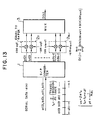
- FIG. 13 is a view showing the theoretical arrangement of a transmitter for digital audio broadcast.
- the carriers having frequencies f 0 to f N-1 are 4-phase-PSK-modulated by combinations of 1 and 0 of two bits of each group.
- FIG. 14 is a view for explaining the function of the frequency multiplexer 3.
- N carriers f 0 to f N-1 having intervals ⁇ f are 4 ⁇ -PSK-modulated by data a(0), b(0); a(1), b(1);...; a(N-1), b(N-1) of N 2-bit groups, and the modulated signals are frequency-multiplexed to be transmitted.
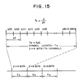
- FIG. 15 is a view for explaining a symbol. One symbol consists of 2 ⁇ N bits.
- every symbol (2 ⁇ N bits) is subjected to 4 ⁇ PSK modulation, and the modulated signals are frequency-multiplexed, thereby sequentially transmitting frequency multiplication signals D(t).
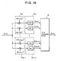
- FIG. 16 is a view showing a theoretical arrangement of a receiver for digital audio broadcast.
- P/S converter parallel/serial converter
- N 4 ⁇ PSK modulators are required.
- N 4 ⁇ PSK demodulators are required to demodulate the baseband signal D(t).
- IDFT Inverse Discrete Fourier Transform
- FIG. 19 is a view showing the arrangement of a main part of a transmitter constituted while giving attention to this point.
- an original signal can be extracted by sampling at N points as in the following description.
- Equation (5) A complex baseband signal obtained after received frequency conversion is expressed in Equation (5).
- the right-hand real-number part and the right-hand real-number part are obtained by deforming D(t) and I(t) by the transmission path and noise.
- the right-hand real-number part and the right-hand real-number part are equal to D(t) and I(t), respectively.
- FIG. 21 is a view showing the arrangement of a main part of a receiver constituted while giving attention to this point.
- Reference numeral 15 denotes a frequency converter; 16a and 16b, low-pass filters; 17a and 17b, A/D converters; and 18, a DFT section.
- FIG. 22 An orthogonal balance modulation scheme using D(t) and I(t) is the same as a frequency conversion scheme used in an SSB scheme as shown in FIG. 22.
- reference numeral 11 denotes an IDFT section; 12a and 12b, AD converters; 13a and 13, low-pass filters; and 14, a frequency converter.
- the frequency converter 14 is constituted by multiplying sections 14a and 14b for multiplying cos ⁇ c t and sin ⁇ c t and a hybrid circuit 14c for synthesizing outputs from the multiplying sections to output a synthesized signal.
- the signal S(t) does not include
- FIG. 23 is a view showing the arrangement of an orthogonal frequency converter using cos ⁇ c t and sin ⁇ c t.
- Equations (12) and (13) coincide with the real-number and imaginary-number parts of Equation (3) representing a complex baseband signal on the transmission side, respectively. Therefore, as has been described above, an original signal can be extracted by performing an N-point sampling DFT arithmetic operation.
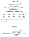
- FIG. 24 is a view for explaining a differential encoder on transmission side.
- a differential decoder 22 is to convert data d L (k) into D L (k) according to the logical equation represented by Equation (15) as shown in FIG. 25. Therefore, in accordance with the cases (1) to (4) of the differential decoder, the following differential decoding results (1) to (4) are output.
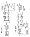
- a transmission system and a reception system in digital audio broadcast using the OFDM scheme have arrangements shown in FIGS. 26A and 26B, respectively.
- reference numeral 14d denotes an oscillator for outputting a cos signal (cos ⁇ c t) of a frequency f c
- reference numeral 14e denotes a phase shifter for shifting the phase of the cos signal by -90° to output -sin ⁇ c t.
- reference numeral 15e denotes an oscillator for outputting a cos signal (cos ⁇ c t) of the frequency f c
- reference numeral 15f is a phase shifter for shifting the phase of the cos signal by -90° to output -sin ⁇ c t.
- a cos wave and a sin wave (carrier) in the transmission system are called transmission local signals
- a cos wave and a sin wave in the reception system are called reception local signals.
- a DAB frame is constituted by a known phase reference symbol and M data symbols.
- Each symbol is divided into N groups each having two bits, the first and second data of each group are encoded as a real-number part and an imaginary-number part, respectively.
- the real-number part and imaginary-number part of a differential code are sequentially input to a Fourier transformer 11, the real-number part and the imaginary-number part output from the Fourier transformer are converted into analog signals, and the analog signals are multiplied by the cos and sin waves of the transmission local frequency fc, respectively.
- the multiplication results are synthesized to be radiated in the space.
- the signal radiated in the space is received, and the received signal is multiplied by cos and sin waves of a reception local frequency.
- the multiplication results are converted into digital signals, and the digital signals are input to a Fourier transformer 18.
- a real-number part and an imaginary-number part output from the Fourier transformer are differentially decoded, and the decoded signals are sequentially output as first and second data serving as original data.
- the Fourier transformer 18 executes a Fourier transformation process on the basis of the generation timing of a DFT window signal. More specifically, a window signal generator (not shown) detects a null signal portion formed between frames to output a DFT window signal serving as a Fourier transformation execution timing of each symbol.
- the Fourier transformer 18 executes Fourier transformation on the basis of the generation timing of the DFT window signal.
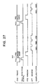
- FIG. 27 is a timing chart for explaining a DAB frame and window signals.
- the start portion of the DAB frame is called a synchronous channel, and is constituted by a null signal portion NULL and a phase reference symbol PRS (Phase Reference Symbol).
- a guard interval GIT of 62 ⁇ s is formed after the null signal portion NULL to reduce the influence of a multipath.
- the null signal portion NULL is formed to find the start of a frame.
- the phase reference symbol PRS is a reference signal for differential decoding and receives a unique pattern (known) inherent in each frame.
- the PRS window is a window arranged at a predetermined time position with reference to the detected null signal portion NULL.
- the DFT window indicates the timing of a DFT arithmetic operation of each symbol.
- the sampling frequencies of AD converters 17a and 17b (FIG. 26) must be made accurately equal to the transmission rate (sampling signal frequency) fs of digital audio data of the transmission side.
- the frequencies shift, or a phase difference occurs the original audio data cannot be correctly demodulated. For this reason, the error amount of the sampling frequency must be monitored, and feedback control must be performed such that the error amount becomes 0.
- an OFDM digital broadcasting system comprising an encoder to encode information from plural information sources, a multiplexer, a communication channel encoder, a selector, a time base, a frame synchronization symbol generator, a pilot symbol generator, and an inverted fast Fourier transformer.
- a pilot signal comprising plural frequencies set orthogonally with each another is transmitted.
- a receiving system for said transmission system is provided with at least a means to estimate the timing offset or frequency offset, or both offsets to occur in itself by estimating the frequency and phase of the pilot signal using the output of the Fourier transformation carried out for said received pilot signal and a means to control the sampling timing or the frequency/phase correction, or a means to control both of them to acquire the timing or frequency synchronization, or both synchronizations using those estimated values.
- a DAB receiver specifies a shift amount between a DAB signal frame and a DAB signal frame transmitted by the above method.
- FIG. 1 is a model of a transmission path.
- Reference numeral 51 denotes a DAB signal transmitter; 52, a DAB receiver; and 53, a transmission path.
- Reference symbol x(n) denotes a transmission signal; h(n), the characteristic of the transmission path, and y(n), a reception signal.
- h(n) impulse response
- a shift amount between a signal frame transmitted by the impulse response and a received signal frame can be specified. More specifically, a reference phase symbol (PRS), included in the start of the frame shown in FIG. 27, for capturing synchronization is represented by X(k), and the received PRS is represented by Y(k), thereby deriving h(n).
- PRS reference phase symbol
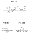
- the impulse position shifts due to signal delay, the impulse position shifts even if the sampling frequencies of the transmitter and the receiver are not equal to each other. For example, when the sampling frequencies of the transmitter and the receiver are not equal to each other in the state wherein no multipath is generated, an impulse response is observed as shown in FIG. 6.
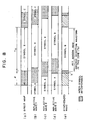
- FIG. 8 is a view for explaining a method of controlling a DFT window position.
- Reference symbol ⁇ denotes a guard interval
- reference symbol Ts denotes a zone of symbol B. In the guard interval ⁇ , the second-half portion of the symbol B is repeatedly inserted.
- the symbol position of a direct wave received by the receiver is as shown in FIG.
- zone a indicates a guard interval zone which is interfered by adjacent symbol A
- zone b a guard interval zone which is not interfered by symbol A
- zone c the zone of symbol B.
- a DFT window WDW must be set at a position where each symbol is DFT-demodulated without being influenced by an adjacent symbol.
- the DFT window WDW is set at a position shown in FIG. 8E.
- the barycentric position of the impulses in the DFT window are calculated, and control is performed on the basis of the barycentric position.
- the start position of the DFT window is represented by 0
- the end position is represented by (N-1)
- that reference symbol N represents a sample number (number of data of a symbol)
- that reference symbol i represents a sample position in the DFT window
- Di represents the amplitude of an impulse at a sample position i.
- the sampling frequency of the A/D converter is free from an error in a multipath generation environment.
- the barycentric position of the impulses in the DFT window changes by a multipath
- the DFT window position also changes as shown in FIG. 10B.
- the start position of the DFT window (PRS window) of the (L+i)th frame is represented by x i
- the impulse barycentric position in the DFT window (PRS window) of the (L+i)th frame is represented by g i
- the shift amount between the DFT windows (PRS windows) in the (L+i)th frame and the (L+i-1)th frame is represented by p i .
- G 2 g 2 ⁇ g 1 ⁇ p 2 ⁇
- G L g L ⁇ g L ⁇ 1 ⁇ p L
- a sampling frequency can also be controlled for each frame.
- the barycentric position of impulses in a DFT window changes by a multipath and the frequency error.
- a DFT window position changes as shown in FIG. 11B.
- a plurality of impulses are generated by a multipath. Even if the position of the DFT window changes, an error component ⁇ F of the sampling frequency of the A/D converter can be extracted, and the sampling frequency can be controlled such that the error component becomes 0.
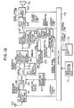
- FIG. 12 is a view showing the arrangement of a DAB receiver according to the present invention.
- Reference numeral 60 denotes a reception antenna; 61, an RF signal demodulator for DAB which multiplies a received signal by cos and sin waves of a carrier frequency to output baseband analog signals D(t) and I(t); 62, an AD converter for converting the baseband analog signals D(t) and I(t) into digital data D(m) and I(m) at a predetermined sampling frequency; 63, a sampling pulse generator for outputting a sampling pulse; 64, a null signal detector for detecting a null signal portion between DAB frames to output a null detection signal NDL; and 65, a DFT window generator for outputting a DFT window signal and a PRS window signal serving as Fourier transformation execution timings of symbols constituting a DAB frame.
- the DFT window generator 65 sets windows (DFT window and PRS window) in a zone which is not interfered by an adjacent symbol.
- Reference numeral 66 denotes a Fourier transformation/differential decoder for performing a Fourier transformation process to the digital data D(m) and I(m) in the PRS window and the DFT window and differentially decoding the digital data D(m) and I(m) to demodulate X(k) (see Equation (16)) and audio code data (e.g., MPEG audio data); 67, an audio signal decoder for decoding the MPEG audio data into a PCM audio data; 68, a DA converter for converting the PCM audio data into analog data; 69, an amplifier; 70, a loudspeaker; 71, an operation key unit; 72, a display unit; and 73, a controller for performing tuning control or other control.
- audio code data e.g., MPEG audio data
- 67 an audio signal decoder for decoding the MPEG audio data into a PCM audio data
- 68 a DA converter for converting the PCM audio data into analog data
- 69 an
- Reference numeral 81 denotes an impulse response arithmetic section for arithmetically operating an impulse response by using a Fourier transformation output X(k) in a PRS window period on the basis of Equation (16); 82, an impulse barycenter arithmetic section for arithmetically operating an impulse barycentric position gi on the basis of Equation (18); and 83, a sampling error extractor for arithmetic operating an error amount ⁇ F of the sampling frequency on the basis of Equations (19) to (21) to output the error amount ⁇ F.
- the RF signal demodulator 61 for DAB multiplies a received signal by cos and sin waves of the carrier frequency to output baseband analog signals D(t) and I(t), and the AD converter 62 converts baseband analog signals D(t) and I(t) into digital data D(m) and I(m) on the basis of a sampling pulse output from the sampling pulse generator 63 to input the digital data D(m) and I(m) to the null signal detector 64 and the Fourier transformation/differential decoder 66.
- the null signal detector 64 detects a null signal portion between DAB frames to output a null detection signal NDT.
- the DFT window generator 65 moves a window to a position which is not interfered by an adjacent symbol depending on a multipath situation to input the window to the Fourier transformation/differential decoder 66, and also inputs the PRS window to the impulse response arithmetic section 81.
- the Fourier transformation/differential decoder 66 When the Fourier transformation/differential decoder 66 performs a Fourier transformation process to the digital data D(m) and I(m) in the PRS window and the DFT window for each symbol, and then differentially decodes the digital data D(m) and I(m) to demodulate X(k) and audio code data (MPEG audio data) and to output them.
- the audio signal decoder 67 decodes the MPEG audio data into PCM audio data
- the DA converter 68 converts the PCM audio data into analog data and inputs the analog data to the loudspeaker 70 through the amplifier 69, thereby outputting DAB voice.
- the impulse response arithmetic section 81 arithmetically operates impulse response by using the Fourier transformation output in the PRS window period on the basis of Equation (16), and inputs the arithmetic result to the DFT window generator 65 and the impulse barycenter calculator 82.
- the DFT window generator 65 moves a window to a position which is not interfered by an adjacent symbol in the next DAB frame on the basis of the impulse response (multipath).
- the impulse barycenter calculator 82 arithmetically operates an impulse barycentric position gi on the basis of Equation (18), and the sampling pulse extractor 83 arithmetically operates the average error amount ⁇ F of the sampling frequencies in L frame periods on the basis of Equations (19) to (21) to input the average error amount ⁇ F to the sampling pulse generator 63.
- the sampling pulse generator 63 controls the sampling frequencies such that the average error amount ⁇ F becomes 0, and inputs a sampling pulse to the AD converter 62.
- the sampling frequency of the transmitter is equal to the sampling frequency of the receiver, and preferable audio voice can be output from the loudspeaker even in a multipath generation environment.
- the sampling frequencies are controlled on the basis of the average error amount ⁇ F of the sampling frequencies in the L frame periods such that the error amount becomes 0.
- a sampling frequency can also be controlled for each frame.
- the sampling pulse extractor 83 can also be constituted as follows. That is, the sampling pulse extractor 83 arithmetically operates the sampling frequency error amount ⁇ F for each frame on the basis of Equations (18), (19), and (21)' and inputs the error amount to the sampling pulse generator 63 to control the sampling frequencies.
- the barycenter of impulse response is calculated for each signal frame of DAB, and an error component of a sampling frequency is extracted in consideration of the position of a DFT window, and the sampling frequency is controlled such that the error becomes 0.
- the sampling frequency of a DAB receiver can be made equal to the sampling frequency of a transmitter even in a multipath environment, and preferable DAB voice can be output.
Landscapes
- Engineering & Computer Science (AREA)
- Signal Processing (AREA)
- Computer Networks & Wireless Communication (AREA)
- Digital Transmission Methods That Use Modulated Carrier Waves (AREA)
- Noise Elimination (AREA)
- Circuits Of Receivers In General (AREA)
Claims (8)
- Empfänger für ein digitales Audio-Broadcasting-System, wobei das digitale Audio-Broadcasting-System ein Übertragungssystem und den Empfänger aufweist und Übertragungsrahmen benutzt, die ein bekanntes Phasenreferenzsymbol PRS und Datensymbole beinhalten, wobei der Empfänger einen Frequenzwandler (15) aufweist für eine Multiplizierung der empfangenen Signale mit einer Cosinus-Welle und einer Sinus-Welle einer Trägerfrequenz, wobei der Empfänger einen AD-Wandler (62) für eine Wandlung der Multiplikationsergebnisse in digitale Signale an einer vorbestimmten Abtastfrequenz, einen Fourier-Transformator (66), der angepasst ist, als Eingabe die digitalen Signale zu empfangen und einen Realteil und einen Imaginärteil als die ersten und zweiten Daten auszugeben, aufweist, wobei der Empfänger weiterhin aufweist:einen Abtastpulsgenerator (63) zur Erzeugung eines Abtastpulses und zur Eingabe des Abtastpulses an den AD-Wandler;einen DFT-Fenster-Generator (65) zur Ausgabe eines DFT-Fenster-Signals, das als eine Fourier-Transformation-Ausführungszeitsteuerung für jedes Symbol dient;eine Impulsantwort-Berechnungseinrichtung (81) zur Berechnung einer Impulsantwort eines Übertragungspfads auf der Basis einer Fourier-Transformationsausgabe des Phasenreferenzsymbols;eine Impulsschwerpunkts-Berechnungseinheit (82) zur Berechnung einer Impulsschwerpunktsposition in dem DFT-Fenster auf der Basis der Position und des Niveaus eines jeden Impulses, der in der berechneten Impulsantwort enthalten ist; undeinen Abtastfehlerextrahierer (83) für das Berechnen eines Veränderungsbetrags der Impulsschwerpunktsposition zwischen Rahmen auf der Basis einer Abweichung zwischen einer DFT-Fensterposition in einem vorhergehenden Rahmen und einer DFT-Fensterposition in einem gegenwärtigen Rahmen, einer Impulsschwerpunktsposition in dem vorhergehenden Rahmen und einer Impulsschwerpunktsposition in dem gegenwärtigen Rahmen, und zur Steuerung der Frequenz des Abtastpulses auf der Basis des Veränderungsbetrags der Impulsschwerpunktsposition zwischen den Rahmen.
- Empfänger nach Anspruch 1, wobei der Abtastpulsgenerator (63) angepasst ist, die Abtastfrequenzen derart zu steuern, dass ein durchschnittlicher Frequenzfehlerbetrag, der berechnet wird, indem ein durchschnittlicher Veränderungsbetrag der Schwerpunktsposition von L-Rahmen verwendet wird, 0 wird, und einen Abtastpuls in den AD-Wandler (62) einzugeben, der generiert wird, indem die Abtastfrequenzen gesteuert werden.
- Empfänger nach Anspruch 1, wobei der DFT-Fenstergenerator (65) angepasst ist, ein vorbestimmtes Fenster an einer Position festzulegen, welche nicht durch ein benachbartes Symbol in dem nächsten Rahmen beeinträchtigt ist, auf der Basis der Impulsantwort.
- Empfänger nach Anspruch 3, wobei der DFT-Fenstergenerator (65) angepasst ist, ein DFT-Fenstersignal und ein PRS-Fenstersignal auszugeben.
- Empfänger nach Anspruch 3, dadurch gekennzeichnet, dass ein Null-Signal-Detektor (64), der mit dem AD-Wandler (62) gekoppelt ist, angepasst ist, einen Null-Signal-Teil zwischen Rahmen zu detektieren, um ein Null-Detektionssignal zu erhalten.
- Empfänger nach Anspruch 5, dadurch gekennzeichnet, dass der DFT-Fenstergenerator (65) angepasst ist, das vorbestimmte Fenster an der Position festzulegen, welche nicht durch das benachbarte Symbol beeinträchtigt ist, wenn ein Null-Detektionssignal eingegeben wird.
- Empfänger nach Anspruch 1, wobei die Impulsantwort, die durch die Impulsantwortberechnungseinrichtung (81) berechnet wird, eine Mehrwegssituation anzeigt.
- Empfänger in digitalem Audio-Broadcasting nach Anspruch 1, wobei die Abtastfrequenz-Steuerungseinrichtung (83) angepasst ist, eine Abtastfrequenz auf der Basis eines durchschnittlichen Veränderungsbetrags einer Schwerpunktsposition von L-Rahmen zu steuern.
Applications Claiming Priority (3)
| Application Number | Priority Date | Filing Date | Title |
|---|---|---|---|
| JP270430/96 | 1996-10-14 | ||
| JP27043096 | 1996-10-14 | ||
| JP27043096A JP3556412B2 (ja) | 1996-10-14 | 1996-10-14 | デジタルオーディオ放送における受信装置 |
Publications (3)
| Publication Number | Publication Date |
|---|---|
| EP0836304A2 EP0836304A2 (de) | 1998-04-15 |
| EP0836304A3 EP0836304A3 (de) | 2001-02-14 |
| EP0836304B1 true EP0836304B1 (de) | 2006-09-27 |
Family
ID=17486175
Family Applications (1)
| Application Number | Title | Priority Date | Filing Date |
|---|---|---|---|
| EP19970117702 Expired - Lifetime EP0836304B1 (de) | 1996-10-14 | 1997-10-13 | Nachfolgung der Abtastfrequenz in einem DAB Empfänger |
Country Status (3)
| Country | Link |
|---|---|
| EP (1) | EP0836304B1 (de) |
| JP (1) | JP3556412B2 (de) |
| DE (1) | DE69736732T2 (de) |
Families Citing this family (10)
| Publication number | Priority date | Publication date | Assignee | Title |
|---|---|---|---|---|
| JPH11346206A (ja) * | 1998-06-02 | 1999-12-14 | Mitsubishi Electric Corp | デジタル放送受信機 |
| JP2955285B1 (ja) | 1998-09-30 | 1999-10-04 | 松下電器産業株式会社 | デジタルオーディオ受信機 |
| GB2344729B (en) * | 1998-12-07 | 2003-09-10 | Mitsubishi Electric Inf Tech | OFDM demodulation |
| GB2352369A (en) * | 1999-07-19 | 2001-01-24 | Oak Technology Inc | Controlling the sampling rate of a receiver |
| DE19937457C2 (de) * | 1999-08-07 | 2003-10-09 | Bosch Gmbh Robert | Verfahren zur Überwachung von Sendern in einem Gleichwellennetz und Anordnung hierfür |
| FR2799597B1 (fr) | 1999-10-08 | 2004-02-20 | Mitsubishi Electric Inf Tech | Procede de transmission de donnees sur porteuses multiples d'un emetteur a un recepteur et recepteur prevu pour la mise en oeuvre dudit procede |
| GB0215639D0 (en) * | 2002-07-05 | 2002-08-14 | British Broadcasting Corp | OFDM receivers |
| EP1396971A1 (de) * | 2002-09-05 | 2004-03-10 | Abb Research Ltd. | Verfahren zur Demodulation der OFDM-Signale mit Abtastratefehlern |
| WO2006068186A1 (ja) * | 2004-12-21 | 2006-06-29 | Matsushita Electric Industrial Co., Ltd. | Ofdm受信装置 |
| US7907673B2 (en) * | 2006-10-26 | 2011-03-15 | Telefonaktiebolaget L M Ericsson (Publ) | Robust and low-complexity combined signal power estimation |
Family Cites Families (2)
| Publication number | Priority date | Publication date | Assignee | Title |
|---|---|---|---|---|
| JP3074103B2 (ja) * | 1993-11-16 | 2000-08-07 | 株式会社東芝 | Ofdm同期復調回路 |
| JP2989742B2 (ja) * | 1994-05-20 | 1999-12-13 | 株式会社日立製作所 | ディジタル放送システムおよび該ディジタル放送用の送信システムならびに該ディジタル放送用の受信システム |
-
1996
- 1996-10-14 JP JP27043096A patent/JP3556412B2/ja not_active Expired - Fee Related
-
1997
- 1997-10-13 DE DE1997636732 patent/DE69736732T2/de not_active Expired - Fee Related
- 1997-10-13 EP EP19970117702 patent/EP0836304B1/de not_active Expired - Lifetime
Also Published As
| Publication number | Publication date |
|---|---|
| DE69736732T2 (de) | 2007-08-16 |
| DE69736732D1 (de) | 2006-11-09 |
| JPH10126353A (ja) | 1998-05-15 |
| EP0836304A2 (de) | 1998-04-15 |
| EP0836304A3 (de) | 2001-02-14 |
| JP3556412B2 (ja) | 2004-08-18 |
Similar Documents
| Publication | Publication Date | Title |
|---|---|---|
| EP1269706B1 (de) | Verfahren zur kompensation von phasenfehlern in mehrträgersignalen | |
| US5787123A (en) | Receiver for orthogonal frequency division multiplexed signals | |
| US5343499A (en) | Quadrature amplitude modulation synchronization method | |
| EP0683576A1 (de) | Digitales OFDM-Rundfunksystem, sowie Übertragungs- und Empfangsvorrichtung für Digitalrundfunk | |
| US5687165A (en) | Transmission system and receiver for orthogonal frequency-division multiplexing signals, having a frequency-synchronization circuit | |
| JPH0746218A (ja) | ディジタル復調装置 | |
| EP1396972B1 (de) | Mehrträgerübertragung zweier Datenmengen | |
| WO1992016063A1 (en) | System for broadcasting and receiving digital data, receiver and transmitter for use in such system | |
| EP0837582B1 (de) | Symbolsynchronisierung in einem Empfänger von digitalen Tonsignalen | |
| EP0836304A2 (de) | Nachfolgung der Abtastfrequenz in einem Empfänger von digitalen Tonsignalen | |
| EP0991238B1 (de) | Erzeugung und Decodierung eines Mehrträgersignals | |
| US7583770B2 (en) | Multiplex signal error correction method and device | |
| WO1995020848A1 (en) | Digital transmission system | |
| JP2001036445A (ja) | Ofdm信号のダイバーシティ受信装置 | |
| US20060002288A1 (en) | Transmission apparatus and method and providing medium thereof | |
| JP3386668B2 (ja) | デジタルオーディオ放送における受信装置 | |
| JP3649560B2 (ja) | 直交周波数分割多重信号発生装置および方法、復調装置、通信装置、直交周波数分割多重信号発生プログラムが格納された記憶媒体および復調プログラムが格納された記憶媒体 | |
| JP3447823B2 (ja) | デジタル放送受信方法 | |
| JP3364339B2 (ja) | デジタル放送における受信装置の同期方法 | |
| JP3549957B2 (ja) | 自動周波数制御方法および装置 | |
| KR100345329B1 (ko) | 직교 주파수 분할 다중화 수신기에서의 샘플링 클럭 복원 장치 및 그 방법 | |
| JP3454762B2 (ja) | Ofdm復調装置における周波数誤差制御回路および方法 | |
| JP3692514B2 (ja) | デジタルfm受信装置 | |
| JP2003110524A (ja) | Ofdm受信装置 | |
| JPH0787056A (ja) | ディジタル復調装置 |
Legal Events
| Date | Code | Title | Description |
|---|---|---|---|
| PUAI | Public reference made under article 153(3) epc to a published international application that has entered the european phase |
Free format text: ORIGINAL CODE: 0009012 |
|
| AK | Designated contracting states |
Kind code of ref document: A2 Designated state(s): DE FR GB |
|
| AX | Request for extension of the european patent |
Free format text: AL;LT;LV;RO;SI |
|
| PUAL | Search report despatched |
Free format text: ORIGINAL CODE: 0009013 |
|
| AK | Designated contracting states |
Kind code of ref document: A3 Designated state(s): AT BE CH DE DK ES FI FR GB GR IE IT LI LU MC NL PT SE |
|
| AX | Request for extension of the european patent |
Free format text: AL;LT;LV;RO;SI |
|
| 17P | Request for examination filed |
Effective date: 20010607 |
|
| AKX | Designation fees paid |
Free format text: DE FR GB |
|
| GRAP | Despatch of communication of intention to grant a patent |
Free format text: ORIGINAL CODE: EPIDOSNIGR1 |
|
| GRAS | Grant fee paid |
Free format text: ORIGINAL CODE: EPIDOSNIGR3 |
|
| GRAA | (expected) grant |
Free format text: ORIGINAL CODE: 0009210 |
|
| AK | Designated contracting states |
Kind code of ref document: B1 Designated state(s): DE FR GB |
|
| REG | Reference to a national code |
Ref country code: GB Ref legal event code: FG4D |
|
| REF | Corresponds to: |
Ref document number: 69736732 Country of ref document: DE Date of ref document: 20061109 Kind code of ref document: P |
|
| ET | Fr: translation filed | ||
| PLBE | No opposition filed within time limit |
Free format text: ORIGINAL CODE: 0009261 |
|
| STAA | Information on the status of an ep patent application or granted ep patent |
Free format text: STATUS: NO OPPOSITION FILED WITHIN TIME LIMIT |
|
| 26N | No opposition filed |
Effective date: 20070628 |
|
| PGFP | Annual fee paid to national office [announced via postgrant information from national office to epo] |
Ref country code: FR Payment date: 20080922 Year of fee payment: 12 |
|
| PGFP | Annual fee paid to national office [announced via postgrant information from national office to epo] |
Ref country code: GB Payment date: 20080919 Year of fee payment: 12 |
|
| PGFP | Annual fee paid to national office [announced via postgrant information from national office to epo] |
Ref country code: DE Payment date: 20080923 Year of fee payment: 12 |
|
| REG | Reference to a national code |
Ref country code: FR Ref legal event code: ST Effective date: 20100630 |
|
| PG25 | Lapsed in a contracting state [announced via postgrant information from national office to epo] |
Ref country code: FR Free format text: LAPSE BECAUSE OF NON-PAYMENT OF DUE FEES Effective date: 20091102 Ref country code: DE Free format text: LAPSE BECAUSE OF NON-PAYMENT OF DUE FEES Effective date: 20100501 |
|
| PG25 | Lapsed in a contracting state [announced via postgrant information from national office to epo] |
Ref country code: GB Free format text: LAPSE BECAUSE OF NON-PAYMENT OF DUE FEES Effective date: 20091013 |