EP0834691A2 - Sanitärarmatur - Google Patents
Sanitärarmatur Download PDFInfo
- Publication number
- EP0834691A2 EP0834691A2 EP97116776A EP97116776A EP0834691A2 EP 0834691 A2 EP0834691 A2 EP 0834691A2 EP 97116776 A EP97116776 A EP 97116776A EP 97116776 A EP97116776 A EP 97116776A EP 0834691 A2 EP0834691 A2 EP 0834691A2
- Authority
- EP
- European Patent Office
- Prior art keywords
- valve
- sanitary fitting
- fitting according
- control
- control element
- Prior art date
- Legal status (The legal status is an assumption and is not a legal conclusion. Google has not performed a legal analysis and makes no representation as to the accuracy of the status listed.)
- Granted
Links
- XLYOFNOQVPJJNP-UHFFFAOYSA-N water Substances O XLYOFNOQVPJJNP-UHFFFAOYSA-N 0.000 claims abstract description 45
- 230000001105 regulatory effect Effects 0.000 abstract description 3
- 230000000694 effects Effects 0.000 abstract 1
- 238000011161 development Methods 0.000 description 4
- 230000018109 developmental process Effects 0.000 description 4
- 238000004519 manufacturing process Methods 0.000 description 2
- 239000000919 ceramic Substances 0.000 description 1
- 230000001419 dependent effect Effects 0.000 description 1
- 238000006073 displacement reaction Methods 0.000 description 1
- 239000000203 mixture Substances 0.000 description 1
- 230000007935 neutral effect Effects 0.000 description 1
- 230000035515 penetration Effects 0.000 description 1
- 238000011144 upstream manufacturing Methods 0.000 description 1
Images
Classifications
-
- G—PHYSICS
- G05—CONTROLLING; REGULATING
- G05D—SYSTEMS FOR CONTROLLING OR REGULATING NON-ELECTRIC VARIABLES
- G05D23/00—Control of temperature
- G05D23/01—Control of temperature without auxiliary power
- G05D23/13—Control of temperature without auxiliary power by varying the mixing ratio of two fluids having different temperatures
- G05D23/1306—Control of temperature without auxiliary power by varying the mixing ratio of two fluids having different temperatures for liquids
- G05D23/132—Control of temperature without auxiliary power by varying the mixing ratio of two fluids having different temperatures for liquids with temperature sensing element
- G05D23/134—Control of temperature without auxiliary power by varying the mixing ratio of two fluids having different temperatures for liquids with temperature sensing element measuring the temperature of mixed fluid
- G05D23/1346—Control of temperature without auxiliary power by varying the mixing ratio of two fluids having different temperatures for liquids with temperature sensing element measuring the temperature of mixed fluid with manual temperature setting means
-
- E—FIXED CONSTRUCTIONS
- E03—WATER SUPPLY; SEWERAGE
- E03C—DOMESTIC PLUMBING INSTALLATIONS FOR FRESH WATER OR WASTE WATER; SINKS
- E03C1/00—Domestic plumbing installations for fresh water or waste water; Sinks
- E03C1/02—Plumbing installations for fresh water
- E03C1/04—Water-basin installations specially adapted to wash-basins or baths
-
- F—MECHANICAL ENGINEERING; LIGHTING; HEATING; WEAPONS; BLASTING
- F16—ENGINEERING ELEMENTS AND UNITS; GENERAL MEASURES FOR PRODUCING AND MAINTAINING EFFECTIVE FUNCTIONING OF MACHINES OR INSTALLATIONS; THERMAL INSULATION IN GENERAL
- F16K—VALVES; TAPS; COCKS; ACTUATING-FLOATS; DEVICES FOR VENTING OR AERATING
- F16K11/00—Multiple-way valves, e.g. mixing valves; Pipe fittings incorporating such valves
- F16K11/02—Multiple-way valves, e.g. mixing valves; Pipe fittings incorporating such valves with all movable sealing faces moving as one unit
- F16K11/06—Multiple-way valves, e.g. mixing valves; Pipe fittings incorporating such valves with all movable sealing faces moving as one unit comprising only sliding valves, i.e. sliding closure elements
- F16K11/078—Multiple-way valves, e.g. mixing valves; Pipe fittings incorporating such valves with all movable sealing faces moving as one unit comprising only sliding valves, i.e. sliding closure elements with pivoted and linearly movable closure members
- F16K11/0782—Single-lever operated mixing valves with closure members having flat sealing faces
- F16K11/0787—Single-lever operated mixing valves with closure members having flat sealing faces with both the supply and the discharge passages being on the same side of the closure members
-
- Y—GENERAL TAGGING OF NEW TECHNOLOGICAL DEVELOPMENTS; GENERAL TAGGING OF CROSS-SECTIONAL TECHNOLOGIES SPANNING OVER SEVERAL SECTIONS OF THE IPC; TECHNICAL SUBJECTS COVERED BY FORMER USPC CROSS-REFERENCE ART COLLECTIONS [XRACs] AND DIGESTS
- Y10—TECHNICAL SUBJECTS COVERED BY FORMER USPC
- Y10T—TECHNICAL SUBJECTS COVERED BY FORMER US CLASSIFICATION
- Y10T137/00—Fluid handling
- Y10T137/8593—Systems
- Y10T137/87249—Multiple inlet with multiple outlet
-
- Y—GENERAL TAGGING OF NEW TECHNOLOGICAL DEVELOPMENTS; GENERAL TAGGING OF CROSS-SECTIONAL TECHNOLOGIES SPANNING OVER SEVERAL SECTIONS OF THE IPC; TECHNICAL SUBJECTS COVERED BY FORMER USPC CROSS-REFERENCE ART COLLECTIONS [XRACs] AND DIGESTS
- Y10—TECHNICAL SUBJECTS COVERED BY FORMER USPC
- Y10T—TECHNICAL SUBJECTS COVERED BY FORMER US CLASSIFICATION
- Y10T137/00—Fluid handling
- Y10T137/8593—Systems
- Y10T137/87571—Multiple inlet with single outlet
- Y10T137/87676—With flow control
- Y10T137/87684—Valve in each inlet
- Y10T137/87692—With common valve operator
Definitions
- the invention is based on a sanitary fitting with a Mixing valve, especially a thermostat.
- Thermostatic valves have two actuators, namely one Element for setting the temperature using the thermostat and a second actuator for opening and Close the valve leading to the outlet. Doing so often the thermostat is set only once and then stays standing at one temperature for a long time.
- the invention has for its object one for the user very easy to use sanitary fitting with improved To create security features.
- the invention proposes a sanitary fitting with the features mentioned in claim 1. Developments of the invention are the subject of dependent claims.
- the Flow control valve for distributing the mixing valve leaving mixed water to one of several outlet lines is trained. You then have a valve with which both the amount of water flowing out as well as the pipe which it exudes, can be adjusted.
- valve in two degrees of freedom actuated control lever as an actuator having.
- the user therefore normally needs d. H. if he doesn't want to change the temperature, just to operate a single actuator.
- the valve can therefore more simply constructed from a design point of view will.
- the two types of actuation can be designed in this way be that they are clearly distinguished by the user can, for example a twist to switch and a perpendicular displacement to open and Conclude.
- the quantity adjustment valve is designed in the manner of a single-lever mixer valve.
- Such single-lever mixer valves are known and the user also common. For example, that the twisting movement usual with normal single-lever mixer valves to change the temperature now to switch is used during the opening and closing movement in in the same way as with the usual single-lever mixer valves. This also prevents accidental incorrect operation locked out.
- the Mixing valve and the flow control valve in one Valve body are housed.
- each valve one in a control surface of a fixed control has an outlet opening.
- Such types of arrangement are known for single-lever mixer valves, so here at least in part on known and available ones Elements can be used.
- each valve has one in a control surface of a fixed control element has outlet opening opening.
- the cold water to be controlled and the hot water to be controlled so enter through the fixed control Quantity setting element on and off again.
- the inlet opening and / or the outlet opening through a control surface of a movable control element more or less closable is.
- the two control elements lie flat against each other, and the movement of the movable control element takes place in the common touch area.
- the mixed water line coming from the thermostatic valve in opens into an opening of a fixed control element, in particular that common to both valves Control.
- control element in which the mixed water line opens can in a further development also have at least two outlet openings, each of which has a separate water channel to one connection for a further one Lead leads.
- connection between the inlet of the mixed water pipe and the outlet openings can in particular also be producible by a movable control element, preferably through the movable control element, which also the two Controls valves.
- the movable control element can be three separate ones Have water channels, so that the three flow paths stay completely separate.
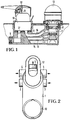
- the sanitary fitting shown in FIGS. 1 and 2 has one common valve body 1.
- This basic body 1 has a connection 2 for a hot water pipe and one Connection 3 for a cold water pipe.
- the valve body is installed so that the hot water supplied through connection 2 and the cold water supplied the connection 3 arrives in the base body 1.
- the Basic body in the example shown three output connections, namely an output terminal 4 for example for a Overhead shower, a connection 5 for a hand shower and one centrally located connection 6 for a bath spout.
- an output terminal 4 for example for a Overhead shower a connection 5 for a hand shower
- one centrally located connection 6 for a bath spout is in as normal spout Fig. 2 arranged above.
- the valve body contains a receptacle 7 for one Thermostatic valve 8 and a second receptacle 9 for one Valve cartridge 10, with the help of the amount of water can be adjusted.
- the valve cartridge 10 is in hers outer shape similar to a single-lever mixer valve.
- a shaft 11 protrudes from the cartridge, to which a conventional handle 12 is attached.
- the handle 12 can be arranged perpendicular to the paper plane in FIG. 1 extending axis is pivoted and about the axis of the shaft 11 be twisted. These two types of actuation are independent from each other.
- thermostatic valve 8 is also a handle in Form of a rotary handle 13 is provided, which by turning on a certain temperature is set.
- the base body 1 there are several channels are present, which are guided so that the input connections 2, 3 via separate channels with the bottom surface of the receptacle 9 in Connect. From the bottom surface of the receptacle 9 leads then a channel 14 for the warm water and a channel 15 for the cold water to the thermostatic valve 8 which is known so that it is not described in detail. Inside the thermostatic valve there is a mixture of cold and warm Water. The mixed water leaves the thermostatic valve a mixed water channel 16, which in turn to the floor area the receptacle 9 for the valve cartridge 10 is guided.
- the valve cartridge 10 is designed so that it is a separate valve for the cold water and a separate one Valve for the hot water forms, the two valves seen in the flow direction in front of the thermostatic valve 8 are arranged. By swiveling more or less of the operating handle 12, the two valves are activated simultaneously opened or closed.
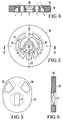
- the flow control valve that contains the valve cartridge 10 is, according to Art a single-lever mixer valve built, so contains, for example a fixed control disc in the cartridge 18, on one side, in Fig. 4 the bottom, with the corresponding channels already mentioned is connected sealed.
- the control disk can, for example consist of ceramic, so that you see in Fig. 3 and in Fig. 4 arranged control surface 19 very smooth is trained.
- the control disk 18 has several openings on, which open in the control surface 19 as openings. It is an inlet opening 20 for the hot water and an opening 21 available for the inlet of the cold water. Both openings are to a center line 22 shown in dash-dotted lines arranged and formed mirror-symmetrically.
- the two Inlet openings 20, 21 extend approximately in an arc shape a center. Practically concentric with these two Openings 20, 21 are further one each through a web 23 interrupted outlet opening 24 for the warm water and an outlet opening 25 for the cold water.
- the Crosspieces 23 serve to reinforce the plate, but are for the function is insignificant.
- the inner ones are Openings 20 and 21 the inlet openings, and the Openings 24, 25 located further out are the outlet openings. It is also possible and is proposed by the invention that this is the other way round, that is, the further out openings if necessary. without the web 23, the inlet openings and the inner openings the outlet openings for this part of the controller.
- the control disc In addition to the inlet and outlet openings for that to the Thermostatic valve flowing water contains the fixed Control disc has a central opening 26 that connects to the mixed water channel 16 is connected. From this in the control surface 19th opening 26, the mixed water enters the control surface a.
- Fig. 5 shows a plan view of the fixed control disc 18 associated movable control disc 28 from the same direction, d. H. from that of the control surface of the movable Control disc 28 opposite side.
- the control surface 29 is the right underside of FIG. 6 movable control disk 28 which on the control surface 19th lies on.
- the movable control disk 28 has three separate ones Breakthroughs 29, 30 and 31.
- Breakthroughs 29, 30 and 31 When assembled 5 lies on the upper side of the movable part which can be seen in FIG Control disc 28 has a cover plate, the individual breakthroughs 29 to 31 separates. Then to the top completed breakthrough 29 is used to manufacture and Remove a connection between the inlet opening 20 and the outlet openings 24, while the opening 30 for the Openings 21 and 25 is responsible.
- the third opening 21 serves to establish a connection between the opening 26 and one of the outlet openings 27.
- the disc 28th For more or less wide simultaneous opening of the Thermostatic valve leading intake valves, the disc 28th shifted in their own longitudinal direction. To switch the Mixed water on the individual outlets is rotated. The openings are arranged so that no twisting leads to a change in the quantity, regardless of the Angular position of the movable control disk 28 a shift in the longitudinal direction always to a uniform opening or Closing movement of the inlet valves leads.
- a butterfly valve described.
- the invention can not only with Can be realized with butterfly valves, but with all types of valves that have a control in can move two degrees of freedom, for example with piston valves and ball valves. Then for piston valves fixed cylinder the fixed and the movable Piston the movable control.
- a mixing valve could also be provided, for example a mixing valve with which only the temperature can be adjusted.
- the mixing valve can be equipped with a pressure compensation valve be combined.
Landscapes
- Engineering & Computer Science (AREA)
- General Engineering & Computer Science (AREA)
- Automation & Control Theory (AREA)
- Physics & Mathematics (AREA)
- Health & Medical Sciences (AREA)
- Life Sciences & Earth Sciences (AREA)
- Hydrology & Water Resources (AREA)
- Public Health (AREA)
- Water Supply & Treatment (AREA)
- General Physics & Mathematics (AREA)
- Mechanical Engineering (AREA)
- Multiple-Way Valves (AREA)
- Temperature-Responsive Valves (AREA)
Abstract
Description
- Fig. 1
- einen Längsschnitt durch eine Sanitärarmatur nach der Erfindung;
- Fig. 2
- eine Vorderansicht der Armatur, d. h. in Fig. 1 von oben;
- Fig. 3
- eine Aufsicht auf die Steuerfläche der feststehenden Steuerscheibe;
- Fig. 4
- einen Querschnitt durch die feststehende Steuerscheibe der Fig. 3;
- Fig. 5
- eine Aufsicht auf die zu der feststehenden Steuerscheibe der Fig. 3 gehörende bewegbare Steuerscheibe;
- Fig. 6
- einen Längsschnitt durch die bewegbare Steuerscheibe der Fig. 5.
Claims (18)
- Sanitärarmatur, mit1.1 einem Kaltwasserzulauf (3),1.2 einem Warmwasserzulauf (2),1.3 einem Mischventil, insbesondere einem Thermostaten (8), sowie mit1.4 einem Mengeneinstellventil, das1.4.1 ein in dem zu dem Mischventil (8) führenden Kaltwasserzulauf angeordnetes Ventil,1.4.2 ein in dem zu dem Mischventil (8) führenden Warmwasserzulauf angeordnetes Ventil und1.4.3 ein die Öffnungsstellung beider Ventile gemeinsam bestimmendes Steuerelement aufweist.
- Sanitärarmatur nach Anspruch 1, bei der das Mengeneinstellventil zum Verteilen des das Mischventil (8) verlassenden Mischwassers auf eine von mehreren Auslaufleitungen (4, 5, 6) ausgebildet ist.
- Sanitärarmatur nach Anspruch 2, bei der die Umschaltung mit Hilfe des Steuerelements des Mengeneinstellventils erfolgt.
- Sanitärarmatur nach einem der vorhergehenden Ansprüche, bei der die Armatur einen in mindestens einer Betätigungsart betätigbaren Steuerhebel als Betätigungsorgan aufweist.
- Sanitärarmatur nach einem der Ansprüche 2 bis 4, bei der das Mengeneinstellventil nach Art eines Einhebelmischventils ausgebildet ist.
- Sanitärarmatur nach einem der vorhergehenden Ansprüche, bei der das Mischventil (8) und das Mengeneinstellventil in einem gemeinsamen Armaturengrundkörper (1) untergebracht sind.
- Sanitärarmatur nach einem der vorhergehenden Ansprüche, bei der jedes Ventil je eine in einer Steuerfläche (19) eines feststehenden Steuerelements (18) ausmündende Einlaßöffnung (20, 21) aufweist.
- Sanitärarmatur nach einem der vorhergehenden Ansprüche, bei der jedes Ventil je eine in einer Steuerfläche (19) eines feststehenden Steuerelements (18) mündende Auslaßöffnung (24, 25) aufweist.
- Sanitärarmatur nach einem der Ansprüche 7 oder 8, bei der die Einlaßöffnung (20, 21) und/oder die Auslaßöffnung (24, 25) durch eine Steuerfläche (29) eines in der gemeinsamen Berührungsfläche bewegbaren Steuerelements (28) verschließbar ist.
- Sanitärarmatur nach einem der Ansprüche 7 bis 9, mit einem für beide Ventile gemeinsamen feststehenden (18) und/oder bewegbaren Steuerelement (28).
- Sanitärarmatur nach einem der Ansprüche 7 bis 10, bei der die von dem Thermostaten (8) kommende Mischwasserleitung (16) in einer Öffnung (26) eines feststehenden Steuerelements (18) mündet.
- Sanitärarmatur nach Anspruch 11, bei der das feststehende Steuerelement (18) mindestens zwei Auslaßöffnungen (27) aufweist, die mit je einem Auslaßanschluß (4) bis (6) verbunden sind.
- Sanitärarmatur nach Anspruch 12, bei der die Verbindung zwischen der Einlaßöffnung (26) für das Mischwasser und den Auslaßöffnungen (27) durch ein bewegbares Steuerelement (28) herstellbar ist.
- Sanitärarmatur nach einem der Ansprüche 11 bis 13, bei der das den Mischwasseröffnungen zugeordnete Steuerelement (28) das den Einlaßventilen zugeordnete Steuerelement ist.
- Sanitärarmatur nach einem der Ansprüche 9 bis 14, bei der das bewegbare Steuerelement (28) drei getrennte Wasserführungen aufweist und/oder bildet.
- Sanitärarmatur nach einem der vorhergehenden Ansprüche, bei der die Steuerelemente die Steuerelemente eines Kolbenventils sind.
- Sanitärarmatur nach einem der vorhergehenden Ansprüche, bei der die Steuerelemente die Steuerelemente eines Kugelventils sind.
- Sanitärarmatur nach einem der vorhergehenden Ansprüche, bei der die Steuerelemente die Steuerscheiben eines Scheibenventils sind.
Priority Applications (1)
| Application Number | Priority Date | Filing Date | Title |
|---|---|---|---|
| DE1998114720 DE19814720A1 (de) | 1997-09-26 | 1998-04-02 | Sanitärventil |
Applications Claiming Priority (3)
| Application Number | Priority Date | Filing Date | Title |
|---|---|---|---|
| DE1996140509 DE19640509A1 (de) | 1996-10-01 | 1996-10-01 | Sanitärarmatur |
| DE19640509 | 1996-10-01 | ||
| US08/941,680 US5960828A (en) | 1996-10-01 | 1997-09-30 | Sanitary fitting |
Publications (3)
| Publication Number | Publication Date |
|---|---|
| EP0834691A2 true EP0834691A2 (de) | 1998-04-08 |
| EP0834691A3 EP0834691A3 (de) | 1998-09-23 |
| EP0834691B1 EP0834691B1 (de) | 2003-06-04 |
Family
ID=26030003
Family Applications (1)
| Application Number | Title | Priority Date | Filing Date |
|---|---|---|---|
| EP97116776A Expired - Lifetime EP0834691B1 (de) | 1996-10-01 | 1997-09-26 | Sanitärarmatur |
Country Status (6)
| Country | Link |
|---|---|
| US (1) | US5960828A (de) |
| EP (1) | EP0834691B1 (de) |
| JP (1) | JP4063928B2 (de) |
| DE (2) | DE19640509A1 (de) |
| DK (1) | DK0834691T3 (de) |
| ES (1) | ES2200103T3 (de) |
Cited By (1)
| Publication number | Priority date | Publication date | Assignee | Title |
|---|---|---|---|---|
| EP4286614A1 (de) * | 2022-06-02 | 2023-12-06 | Ideal Standard International NV | Sanitärarmatur mit absperrventilen |
Families Citing this family (14)
| Publication number | Priority date | Publication date | Assignee | Title |
|---|---|---|---|---|
| DE10149516C1 (de) * | 2001-10-08 | 2003-02-20 | Hansa Metallwerke Ag | Sanitäreinrichtung |
| US6676024B1 (en) | 2002-09-05 | 2004-01-13 | Masco Corporation | Thermostatic valve with electronic control |
| DE602004017766D1 (de) * | 2003-09-25 | 2008-12-24 | Greens Ind Ltd | Auf einhebelventile anwendbare temperaturbegrenzungsvorrichtung zum mischen von heissen und kalten flüssigkeiten |
| US7343923B2 (en) * | 2005-07-28 | 2008-03-18 | Foster Jody R | Utility hot and cold water mixing system |
| GB0526331D0 (en) * | 2005-12-23 | 2006-02-01 | Horne Engineering Co Ltd | Mixer tap |
| US8578966B2 (en) | 2006-07-28 | 2013-11-12 | Masco Corporation Of Indiana | Mixing valve |
| US7753074B2 (en) | 2006-07-28 | 2010-07-13 | Masco Corporation Of Indiana | Mixing valve |
| WO2012089069A1 (zh) * | 2010-12-29 | 2012-07-05 | 厦门松霖科技有限公司 | 能切换水路和调节流量的阀 |
| FR2974876B1 (fr) * | 2011-05-05 | 2013-06-14 | First Labo | Dispositif de distribution d'un fluide thermostate avec des alimentations eau froide / eau chaude isolees |
| WO2014018564A1 (en) | 2012-07-23 | 2014-01-30 | Zieger Claus Dieter | Multiple proportion delivery systems and methods |
| CN105650308B (zh) * | 2016-03-29 | 2017-12-22 | 宁波慈立恒温科技有限公司 | 一种恒温龙头 |
| CN206221711U (zh) * | 2016-10-27 | 2017-06-06 | 厦门建霖工业有限公司 | 一种双阀芯净水龙头 |
| ES1171585Y (es) * | 2016-11-21 | 2017-02-27 | Caspro Sa | Grifo mono-mando |
| CN107676505B (zh) * | 2017-09-22 | 2023-08-22 | 台州市国人温控卫浴科技有限公司 | 一种含压力平衡阀的恒温水龙头主体结构 |
Citations (1)
| Publication number | Priority date | Publication date | Assignee | Title |
|---|---|---|---|---|
| EP0246405A1 (de) | 1986-03-22 | 1987-11-25 | FRIEDRICH GROHE ARMATURENFABRIK GmbH & CO | Sanitärarmatur |
Family Cites Families (9)
| Publication number | Priority date | Publication date | Assignee | Title |
|---|---|---|---|---|
| US3840046A (en) * | 1973-09-13 | 1974-10-08 | A Busquets | Three outlet mixing and diverter valve |
| US4444215A (en) * | 1981-07-02 | 1984-04-24 | Eaton Corporation | Mixing valve |
| DE3419208A1 (de) * | 1984-05-23 | 1985-11-28 | Hans Grohe Gmbh & Co Kg, 7622 Schiltach | Steuereinsatz fuer sanitaere mischarmaturen |
| CH681385A5 (de) * | 1989-11-16 | 1993-03-15 | Karrer Weber & Cie Ag | |
| EP0501953B1 (de) * | 1989-11-25 | 1993-04-21 | Ideal-Standard Gmbh | Sanitäre mischbatterie |
| JP2874322B2 (ja) * | 1990-10-05 | 1999-03-24 | 東陶機器株式会社 | 湯水混合水栓 |
| US5462224A (en) * | 1990-10-05 | 1995-10-31 | Toto Ltd. | Hot and cold water mixing discharge device |
| DE4120024A1 (de) * | 1991-06-05 | 1992-12-10 | Ideal Standard | Sanitaere mischbatterie mit thermostatregelung |
| DE4423853C2 (de) * | 1994-07-07 | 2002-10-24 | Hansgrohe Ag | Einhebelmischventil |
-
1996
- 1996-10-01 DE DE1996140509 patent/DE19640509A1/de not_active Withdrawn
-
1997
- 1997-09-26 EP EP97116776A patent/EP0834691B1/de not_active Expired - Lifetime
- 1997-09-26 DK DK97116776T patent/DK0834691T3/da active
- 1997-09-26 ES ES97116776T patent/ES2200103T3/es not_active Expired - Lifetime
- 1997-09-26 DE DE59710208T patent/DE59710208D1/de not_active Expired - Fee Related
- 1997-09-30 US US08/941,680 patent/US5960828A/en not_active Expired - Lifetime
- 1997-09-30 JP JP28121797A patent/JP4063928B2/ja not_active Expired - Fee Related
Patent Citations (1)
| Publication number | Priority date | Publication date | Assignee | Title |
|---|---|---|---|---|
| EP0246405A1 (de) | 1986-03-22 | 1987-11-25 | FRIEDRICH GROHE ARMATURENFABRIK GmbH & CO | Sanitärarmatur |
Cited By (1)
| Publication number | Priority date | Publication date | Assignee | Title |
|---|---|---|---|---|
| EP4286614A1 (de) * | 2022-06-02 | 2023-12-06 | Ideal Standard International NV | Sanitärarmatur mit absperrventilen |
Also Published As
| Publication number | Publication date |
|---|---|
| DE59710208D1 (de) | 2003-07-10 |
| JPH10122393A (ja) | 1998-05-15 |
| ES2200103T3 (es) | 2004-03-01 |
| JP4063928B2 (ja) | 2008-03-19 |
| DK0834691T3 (da) | 2003-09-29 |
| US5960828A (en) | 1999-10-05 |
| EP0834691A3 (de) | 1998-09-23 |
| DE19640509A1 (de) | 1998-04-02 |
| EP0834691B1 (de) | 2003-06-04 |
Similar Documents
| Publication | Publication Date | Title |
|---|---|---|
| EP0162342B1 (de) | Steuereinsatz für sanitäre Mischarmaturen | |
| EP0834691B1 (de) | Sanitärarmatur | |
| DE3310080C2 (de) | Mischventil | |
| EP0811184B1 (de) | Mischhahnbatteriekartusche mit thermostatischer temperaturregelung | |
| DE60022787T2 (de) | Mehrwegventil | |
| DE4308994C1 (de) | Sanitäres Mischventil | |
| EP1022635B1 (de) | Sanitäres Thermostatventil | |
| EP1022634B1 (de) | Kartusche für Sanitärarmaturen | |
| DE102004018277B4 (de) | Mischventil für eine einarmige, nur durch Drehen betätigbare Mischbatterie | |
| EP1022637B1 (de) | Thermostatventil | |
| EP1319144B1 (de) | Kartusche für eine sanitärarmatur | |
| EP1261822B1 (de) | Temperaturgeregeltes mischventil | |
| EP1794484B1 (de) | Abstell- und umstellventil | |
| DE3525053A1 (de) | Sanitaeres ventil | |
| AT393154B (de) | Zum vermischen von warmwasser und kaltwasser dienendes mischventil | |
| AT400868B (de) | Sanitärarmatur | |
| DE3043089A1 (de) | Mechanisch betaetigte brauchwassermischbatterie | |
| EP0263811B1 (de) | Sanitäre Eingriff-Mischbatterie | |
| DE2911965C2 (de) | Mischventil | |
| DE2123914A1 (de) | Mehrwegehahn, insbesondere Mischventil | |
| DE19814720A1 (de) | Sanitärventil | |
| EP1234917A1 (de) | Sanitärarmatur | |
| EP0187179B1 (de) | Armatur für über der Armatur montierte überlauf-Heisswassergeräte | |
| DE3041696A1 (de) | Mischbatterie | |
| DD231614A1 (de) | Thermostatisch geregelte mischbatterie |
Legal Events
| Date | Code | Title | Description |
|---|---|---|---|
| PUAI | Public reference made under article 153(3) epc to a published international application that has entered the european phase |
Free format text: ORIGINAL CODE: 0009012 |
|
| AK | Designated contracting states |
Kind code of ref document: A2 Designated state(s): CH DE DK ES FR GB IT LI NL |
|
| AX | Request for extension of the european patent |
Free format text: AL;LT;LV;RO;SI |
|
| PUAL | Search report despatched |
Free format text: ORIGINAL CODE: 0009013 |
|
| AK | Designated contracting states |
Kind code of ref document: A3 Designated state(s): AT BE CH DE DK ES FI FR GB GR IE IT LI LU MC NL PT SE |
|
| AX | Request for extension of the european patent |
Free format text: AL;LT;LV;RO;SI |
|
| 17P | Request for examination filed |
Effective date: 19990319 |
|
| AKX | Designation fees paid |
Free format text: CH DE DK ES FR GB IT LI NL |
|
| RBV | Designated contracting states (corrected) |
Designated state(s): CH DE DK ES FR GB IT LI NL |
|
| 17Q | First examination report despatched |
Effective date: 20010817 |
|
| GRAH | Despatch of communication of intention to grant a patent |
Free format text: ORIGINAL CODE: EPIDOS IGRA |
|
| GRAH | Despatch of communication of intention to grant a patent |
Free format text: ORIGINAL CODE: EPIDOS IGRA |
|
| GRAA | (expected) grant |
Free format text: ORIGINAL CODE: 0009210 |
|
| RAP1 | Party data changed (applicant data changed or rights of an application transferred) |
Owner name: HANSGROHE AG |
|
| AK | Designated contracting states |
Designated state(s): CH DE DK ES FR GB IT LI NL |
|
| REG | Reference to a national code |
Ref country code: GB Ref legal event code: FG4D Free format text: NOT ENGLISH |
|
| REG | Reference to a national code |
Ref country code: CH Ref legal event code: NV Representative=s name: SULZER MANAGEMENT AG Ref country code: CH Ref legal event code: EP |
|
| GBT | Gb: translation of ep patent filed (gb section 77(6)(a)/1977) | ||
| REF | Corresponds to: |
Ref document number: 59710208 Country of ref document: DE Date of ref document: 20030710 Kind code of ref document: P |
|
| REG | Reference to a national code |
Ref country code: DK Ref legal event code: T3 |
|
| REG | Reference to a national code |
Ref country code: ES Ref legal event code: FG2A Ref document number: 2200103 Country of ref document: ES Kind code of ref document: T3 |
|
| ET | Fr: translation filed | ||
| PLBE | No opposition filed within time limit |
Free format text: ORIGINAL CODE: 0009261 |
|
| STAA | Information on the status of an ep patent application or granted ep patent |
Free format text: STATUS: NO OPPOSITION FILED WITHIN TIME LIMIT |
|
| 26N | No opposition filed |
Effective date: 20040305 |
|
| PGFP | Annual fee paid to national office [announced via postgrant information from national office to epo] |
Ref country code: ES Payment date: 20070925 Year of fee payment: 11 Ref country code: DK Payment date: 20070925 Year of fee payment: 11 |
|
| PGFP | Annual fee paid to national office [announced via postgrant information from national office to epo] |
Ref country code: CH Payment date: 20070924 Year of fee payment: 11 |
|
| PGFP | Annual fee paid to national office [announced via postgrant information from national office to epo] |
Ref country code: GB Payment date: 20070921 Year of fee payment: 11 |
|
| PGFP | Annual fee paid to national office [announced via postgrant information from national office to epo] |
Ref country code: NL Payment date: 20070917 Year of fee payment: 11 Ref country code: IT Payment date: 20070927 Year of fee payment: 11 Ref country code: DE Payment date: 20071022 Year of fee payment: 11 |
|
| PGFP | Annual fee paid to national office [announced via postgrant information from national office to epo] |
Ref country code: FR Payment date: 20070926 Year of fee payment: 11 |
|
| REG | Reference to a national code |
Ref country code: CH Ref legal event code: PL |
|
| REG | Reference to a national code |
Ref country code: DK Ref legal event code: EBP |
|
| GBPC | Gb: european patent ceased through non-payment of renewal fee |
Effective date: 20080926 |
|
| PG25 | Lapsed in a contracting state [announced via postgrant information from national office to epo] |
Ref country code: NL Free format text: LAPSE BECAUSE OF NON-PAYMENT OF DUE FEES Effective date: 20090401 |
|
| NLV4 | Nl: lapsed or anulled due to non-payment of the annual fee |
Effective date: 20090401 |
|
| REG | Reference to a national code |
Ref country code: FR Ref legal event code: ST Effective date: 20090529 |
|
| PG25 | Lapsed in a contracting state [announced via postgrant information from national office to epo] |
Ref country code: IT Free format text: LAPSE BECAUSE OF NON-PAYMENT OF DUE FEES Effective date: 20080926 Ref country code: DE Free format text: LAPSE BECAUSE OF NON-PAYMENT OF DUE FEES Effective date: 20090401 |
|
| PG25 | Lapsed in a contracting state [announced via postgrant information from national office to epo] |
Ref country code: LI Free format text: LAPSE BECAUSE OF NON-PAYMENT OF DUE FEES Effective date: 20080930 Ref country code: FR Free format text: LAPSE BECAUSE OF NON-PAYMENT OF DUE FEES Effective date: 20080930 Ref country code: CH Free format text: LAPSE BECAUSE OF NON-PAYMENT OF DUE FEES Effective date: 20080930 |
|
| REG | Reference to a national code |
Ref country code: ES Ref legal event code: FD2A Effective date: 20080927 |
|
| PG25 | Lapsed in a contracting state [announced via postgrant information from national office to epo] |
Ref country code: GB Free format text: LAPSE BECAUSE OF NON-PAYMENT OF DUE FEES Effective date: 20080926 |
|
| PG25 | Lapsed in a contracting state [announced via postgrant information from national office to epo] |
Ref country code: ES Free format text: LAPSE BECAUSE OF NON-PAYMENT OF DUE FEES Effective date: 20080927 |
|
| PG25 | Lapsed in a contracting state [announced via postgrant information from national office to epo] |
Ref country code: DK Free format text: LAPSE BECAUSE OF NON-PAYMENT OF DUE FEES Effective date: 20090331 |