EP0832751B1 - Ink-jet recording apparatus with high and low color-density inks - Google Patents
Ink-jet recording apparatus with high and low color-density inks Download PDFInfo
- Publication number
- EP0832751B1 EP0832751B1 EP97116791A EP97116791A EP0832751B1 EP 0832751 B1 EP0832751 B1 EP 0832751B1 EP 97116791 A EP97116791 A EP 97116791A EP 97116791 A EP97116791 A EP 97116791A EP 0832751 B1 EP0832751 B1 EP 0832751B1
- Authority
- EP
- European Patent Office
- Prior art keywords
- ink
- ink cartridge
- density
- recording apparatus
- jet recording
- Prior art date
- Legal status (The legal status is an assumption and is not a legal conclusion. Google has not performed a legal analysis and makes no representation as to the accuracy of the status listed.)
- Expired - Lifetime
Links
- 239000000976 ink Substances 0.000 title claims description 466
- 239000003086 colorant Substances 0.000 claims description 18
- 238000004140 cleaning Methods 0.000 claims description 12
- 238000003491 array Methods 0.000 claims description 4
- 238000006073 displacement reaction Methods 0.000 claims description 2
- 238000010276 construction Methods 0.000 description 8
- 239000013013 elastic material Substances 0.000 description 2
- 238000000034 method Methods 0.000 description 2
- 230000007812 deficiency Effects 0.000 description 1
- 238000007599 discharging Methods 0.000 description 1
- 239000000428 dust Substances 0.000 description 1
- 239000000463 material Substances 0.000 description 1
- 230000003278 mimic effect Effects 0.000 description 1
- 238000012986 modification Methods 0.000 description 1
- 230000004048 modification Effects 0.000 description 1
- 238000005192 partition Methods 0.000 description 1
- 239000011148 porous material Substances 0.000 description 1
- 238000009877 rendering Methods 0.000 description 1
- 239000002699 waste material Substances 0.000 description 1
Images
Classifications
-
- B—PERFORMING OPERATIONS; TRANSPORTING
- B41—PRINTING; LINING MACHINES; TYPEWRITERS; STAMPS
- B41J—TYPEWRITERS; SELECTIVE PRINTING MECHANISMS, i.e. MECHANISMS PRINTING OTHERWISE THAN FROM A FORME; CORRECTION OF TYPOGRAPHICAL ERRORS
- B41J2/00—Typewriters or selective printing mechanisms characterised by the printing or marking process for which they are designed
- B41J2/005—Typewriters or selective printing mechanisms characterised by the printing or marking process for which they are designed characterised by bringing liquid or particles selectively into contact with a printing material
- B41J2/01—Ink jet
- B41J2/205—Ink jet for printing a discrete number of tones
- B41J2/2056—Ink jet for printing a discrete number of tones by ink density change
Definitions
- the present invention pertains generally to an ink jet recording apparatus that utilizes an ink cartridge to record on a printing medium, and more particularly to an ink jet printer that includes both high color-density and low color-density inks such as known from EP-A-0 627 323 and EP-A-0 626 266.
- the present invention relates also to an ink cartridge itself containing both high and low color-density inks.
- a color ink jet recording apparatus of this type is constructed so that color inks such as black, yellow, magenta, and cyan inks are loaded into a print cartridge to permit the ink jet printer to produce a plurality of colors that mimic the full range of colors available in a standard color printer.
- a conventional example of such an apparatus is disclosed in Unexamined Japanese Patent Publication No. Hei. 8-58075.
- the main feature of this prior art ink jet recording apparatus is that high color-density inks and low color-density inks are contained in a single ink cartridge for each color, so that the printer can print using variable ink color-density.
- ink dots that would typically be noticeable as highlighted portions may be replaced with ink dots recorded with lower color-density ink thereby rendering the dots unnoticeable and producing a more natural image.
- a high-definition recording can be provided, especially where the apparatus is used to print photographs.
- an ink jet printer for printing information onto a recording medium.
- the printer utilizes high color-density inks of a plurality of different colors and low color-density inks of a plurality of different colors, and further includes a first ink cartridge unit that contains the high color-density inks of a plurality of different colors, and a second ink cartridge unit that contains the low color-density inks of a plurality of different colors.
- an ink jet recording apparatus of the present invention includes a supply roller for supplying the sheet in a sheet feed direction.
- a carriage is slidably mounted within the ink jet printer for displacement in a scanning direction.
- a head is mounted on the carriage, and a first ink cartridge containing high color-density inks of a plurality of colors and a second ink cartridge containing low color-density inks of a plurality of colors are mounted on the carriage for supplying ink to the head.
- an object of the invention is to provide an ink jet recording apparatus that can effectively use high and low color-density inks and reduce costs by overcoming the aforementioned problems accompanying conventional devices.
- Another object of the invention is to provide an ink jet recording apparatus with an improved printing efficiency by optimally positioning the ink supply ports of an ink cartridge containing high color-density ink, and an ink cartridge containing low color-density ink.
- Still another object of the invention is to provide an ink jet recording apparatus that enables a stable resolution printing processes by providing a structure for cleaning the individual ink color nozzles.
- Yet another object of the invention is to provide an ink jet recording apparatus that allows inks to be used uniformly by providing only some inks of the same color-density, so that inks may be used without waste.
- a further object of the invention is to provide an ink jet recording apparatus that can avoid wasting ink by detecting when the ink in a particular cartridge has been exhausted.
- Another object of the invention is to provide an ink jet recording apparatus that allows high and low color-density ink cartridges to be removably attached without error by providing a means of identifying cartridges that contain high color-density ink and cartridges that contain low color-density ink.
- Another object of the invention is to provide an ink jet recording apparatus that can check the attached conditions of ink cartridges safely, so that erroneous operation can be prevented.
- Yet another object of the invention is to provide an ink jet recording apparatus that allows only an unused ink cartridge to be used for printing, so that printing quality can be ensured.
- Still another object of the invention is to provide an ink jet recording apparatus that simplifies the structure of the printer by integrating an ink cartridge with a recording head.
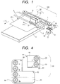
- an ink jet printer or recording apparatus is generally indicated at 100 and is constructed in accordance with the preferred embodiment of the invention.
- An ink jet printer 100 includes at least one feed roller 1 mounted within printer 100 and driven by a step motor (not shown). Feed roller 1 feeds a sheet S of a recording medium to a platen 2 in a sheet feed direction Y, perpendicular to the length direction of feed roller 1.
- a carriage 3 is slidably mounted on rails 6, which are mounted within the body of printer 100. Carriage 3 supports an ink jet head 4 thereon for ejecting ink droplets onto sheet S.
- Carriage 3 is coupled to a timing belt 8 that is driven by a step motor 7, and is reciprocally displaceable in a scanning direction X along guide rails 6. Scanning direction X is substantially orthogonal to sheet feed direction Y.
- a sheet stacker 5 is disposed within printer 100 to provide a platform from which sheets S may be fed by feed roller 1.
- recording head 4 is mounted on carriage 3.
- An ink cartridge 50 is attached to recording head 4, and includes a high color-density ink cartridge 51 and a low color-density ink cartridge 52.
- Ink cartridge 50 may be integral with or separate from recording head 4.
- ink cartridges 51 and 52 extend so as to be positioned adjacent to each other in scanning direction X.
- High color-density ink cartridge 51 and low color-density ink cartridge 52 each are preferably constructed as separate ink containers, arranged side-by-side.
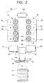
- Low color-density ink cartridge 51 and high color-density ink cartridge 52 each include a plurality of ink chambers 53 having partition walls 56 and a common, outer case 54. Separate ink chambers 53 contain a plurality of different inks.
- ink chambers 53 contain high color-density cyan ink (denoted as C) and low color-density cyan ink (denoted as c), and high and low color-density magenta (M, m), yellow (Y, y), and black (Bk, bk) inks.
- High color-density inks have a higher in color-density than low color-density inks.
- a plurality of ink supply ports 55 for introducing inks from the respective ink chambers 53 are provided for each ink chamber 53 contained in ink cartridge 50, with high color-density ink supply ports denoted as 55a, and low color-density ink supply ports denoted as 55b.
- high color-density ink supply ports 55a can be positioned adjacent low color-density ink supply ports 55b in the sheet feed direction.
- a nozzle plate 42 is disposed on a lower surface of recording head 4, and includes a plurality of nozzles 41 that extend in the sheet feed direction Y to form nozzle arrays 45.
- Nozzles 41 are arranged in the form of a plurality of arrays 45 that include, for example, a low color-density black ink nozzle array bk and a high color-density black ink nozzle array Bk.
- Recording head 4 includes a plurality of pressure chambers, whose construction is well known in the art, that communicate separately with each of the plurality of nozzles and ink chambers 53 (described below). Hollow ink supply needles 44 are formed on the top surface of recording head 4.
- a plurality of throughholes are formed on the tips of supply needles 44 for communicating within ink chambers 53 through needles 44 to ink supply passages 43 formed in recording head 4. This allows ink contained within ink chambers 53-56 to travel from the chambers to nozzles 41.
- Recording head 4 includes multiple ink supply passages 43 for supplying inks from the common ink chambers.
- high color-density ink supply needles 44a and low color-density ink supply needles 44b are arranged in the scanning direction so as to be positioned to compliment respective high and low color-density ink supply ports 55a and 55b.
- Ink supply needles 44 are designed to be connected to ink supply ports 55 of ink cartridge 50.
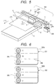
- a cartridge 150 includes a high color-density ink cartridge 151 and a low color-density ink cartridge 152.
- the high color-density ink supply ports 155a and low color-density ink supply ports 155b are spaced apart in the sheet feed direction, and the respective high and low color-density ink supply needles 144a and 144b are formed on head 4 so as to correspond to the location of ink supply ports 155.
- the position of ink supply cartridges 51, 52 and ink supply ports 55 may be changed by altering the attachment pattern of ink cartridge 50.
- high color-density ink cartridge 51 may be positioned above low color-density ink cartridge 52 in a direction orthogonal to both the scanning and sheet feed directions.
- high color-density ink cartridge 51 may be adjacent low color-density ink cartridge 52 in the scanning direction.
- printer 100 may be provided with a position sensor (not shown) to detect the manner in which ink cartridge 50 is attached, and to detect whether high color-density ink cartridge 51 and low color-density ink cartridge 52 are properly attached to head 4.
- a position sensor can be set to prevent operation of printer 100 when either high color-density ink cartridge 51 or low color-density ink cartridge 52 are not properly engaged with head 4.
- printer 100 includes a cleaning section 9.
- Cleaning section 9 is large enough to cover nozzles 41 of recording head 4, and includes a cap 91 formed of an elastic material containing a porous member.
- Cap 91 may include a cap 91a for high color-density ink and a cap 91b for low color-density ink, which are positioned to cover nozzles 41 of recording head 4 corresponding to ink cartridges 51 and 52.
- Cleaning section 9 includes pumps 57 and 59, which are connected to cap 91 through a pipe, for forcibly discharging inks from nozzles 41 in the event the nozzles 41 become clogged. While cleaning section 9 is depicted having two pumps, the invention contemplates using one pump as well. When nozzles 41 of recording head 4 are to be unclogged, the openings of nozzles 41 are covered with cap 91 and a negative pressure is produced within cap 91 by operation of the pump so as to forcibly discharge the clogged ink from nozzles 41.
- Cleaning section 9 also includes a wiper member made of an elastic material, such as rubber, and a rubbing member made of a porous material, which are not shown. The wiper member cleans dust and unnecessary ink deposited on the nozzle surfaces of recording head 4.
- cap 91 may be divided into ink caps that can be positioned to cover the high and low color-density ink nozzle openings of a common color.
- cap 91 may be constructed to have four separate ink caps, one for each color shown in FIGS. 2-4. In this manner, one ink cap is provided for the high and low color-density ink having a yellow hue. Similarly, another ink cap is provided for the high and low color-density inks having black, cyan and magenta hues.
- the remaining construction of cleaner 9 is similar to that described above.
- the ink jet printer operates as follows. As shown in FIGS. 1 and 2, high color-density ink cartridge 51 and low color-density ink cartridge 52 are mounted on carriage 3 and are aligned in the scanning direction X to be adjacent to each other. Ink cartridge 50 is positioned on carriage 3 so that ink supply needles 44 of recording head 4 cooperatively fit into ink supply ports 55. To print characters or images, the printer operator commands a print operation, and, as a result, print sheet S is fed by sheet feed roller 1 from sheet stacker 5 and forwarded on the surface of platen 2 in the sheet feed direction.
- carriage 3 is pulled by timing belt 8 in the scanning direction along guide rail 6 under power of step motor 7, and inks supplied from ink chambers 53 within ink cartridge 50 via ink supply needles 44 and ink supply passages 43 are ejected onto sheet S from nozzles 41.
- Sheet S is then subjected to further printing and is progressively fed in sheet feeding direction Y until it is discharged onto a containing section (not shown).
- high-quality printing may be implemented by furnishing ink supply commands that call for the high and low color-density inks contained in the ink chambers 53 of ink cartridge 50 to be supplied selectively. That is, for printing dark or dense presentation materials, high color-density inks are mainly supplied from high color-density ink cartridge 51, whereas for printing photographs that include highlighted or diffuse portions, low color-density inks are mainly supplied from low color-density ink cartridge 52.
- printer 100 is provided with an ink exhaustion detector 180 that can detect when an ink chamber is depleted by a projection, an electric contact, or another means known to those skilled in the art.
- high color-density ink cartridge 51 and/or low color-density ink cartridge 52 are provided with an identifying characteristic 200 that identifies ink cartridge 51 as a high color-density ink cartridge and/or identifies ink cartridge 52 as a low color-density ink cartridge.
- Identifying characteristic 200 may be constructed by using an element for converting electrical energy to mechanical energy on a drive section of recording head 4 or by using an element for converting electrical energy to heat on the drive section of recording head 4 or by other techniques known in the art.
- high color-density ink cartridge 51 or low color-density ink cartridge 52 may be selectively removed from ink cartridge 50 for replacement because both high color-density ink cartridge 51 and low color-density ink cartridge 52 are integrated, unitary bodies containing inks of different colors in their respective ink chambers 53.
- the high color-density inks and low color-density inks that heretofore were wasted may be used for printing purposes until a particular ink is depleted. As a result, running costs can be reduced significantly.
- ink cartridge 150 includes a set of low color-density ink supply needles 144a and a set of high color-density ink supply needles 144b, each set of supply needles 144a, 144b extending in the scanning direction.
- Low color-density ink supply needles 144a are spaced apart from high color-density ink supply needles 144b.
- low color-density ink supply needles 144a are arranged at a remote position in the sheet feed direction from high color-density ink supply needles 144b.
- Ink cartridge 150 includes ink supply ports 155, which are positioned to be engageable with low and high color-density ink supply needles 144a and 144b. In this manner, low color-density ink cartridge 152 can be constructed to have a larger (or smaller) ink capacity than high color-density ink cartridge 151.
- a user may specify the more appropriate combination of cartridges and cartridge capacities. That is, where the images to be printed have predominantly highlighted portions, the capacity of the low color-density ink cartridge may be increased to provide more low color-density ink to more efficiently match the type of ink to the type of image to be printed.
- the user may alter the capacity of either low or high color-density ink depending on the type of image to be printed, without altering the arrangement of the supply needles because of the remote location of supply ports 55.
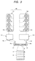
- ink cartridge 250 includes high and low color-density inks in cyan and magenta, but only one color-density of yellow and black ink. Because cyan and magenta are colors used to produce high-quality images, some users may find it advantageous to have two color-densities of cyan and magenta ink, but may-not require different color-densities of yellow and black.
- high color-density ink cartridge 251 can be formed in an L-shaped, and can include at least one recessed portion 60
- low color-density ink cartridge 252 can be formed in a rectangular shape, and can include at least one projected portion 61.
- one projected portion 61 is constructed and arranged on diagonally opposite corners of low color-density ink cartridge 252 to engage recessed portions 60 of high color-density ink cartridge 251 such that high and low color-density ink cartridges 251 and 252, when engaged, form integral ink cartridge 250.
- low color-density ink cartridge 252 may be formed having ink chambers 253 of only cyan and magenta, in a configuration like that shown in FIG. 4, or any arrangement having a different number of ink cartridges than high color-density ink cartridge 251.
- low color-density ink cartridge 252 may be formed in the configuration of FIG. 3 without providing ink chambers for yellow and black low color-density inks. That is, so long as each ink is provided an appropriate supply port 255, low color-density ink cartridge 252 may be formed such that the quantity and number of different colored inks is variable.
- high color-density ink cartridge 251 may be formed such that the capacity of high color-density ink cartridge 251 is increased compared to low color-density ink cartridge 252 by allocating some of the capacity of low color-density ink cartridge 252 to high color-density ink cartridge 251.
- this embodiment facilitates the user's ability to manage the use of ink cartridges because the user can select ink cartridge 250 according to the quantities of inks to be consumed.
- a printer 300 is constructed similarly to that depicted in FIG. 1 except that high color-density ink chambers 353a of high color-density ink cartridge 351 and low color-density ink chambers 353b of low color-density ink cartridge 352 are constructed and arranged on carriage 3 such that each chamber spans the length of ink cartridge 350 in scanning direction X and supply ports 355 are aligned in paper feed direction Y.
- the ink supply needles (not shown) are arranged in a single row in sheet feed direction Y to engage ink supply ports 355 as shown in FIG. 6.
- cleaning section 309 is modified to cap the different arrangement of nozzle openings of recording head 4. Rather than having ink caps 91 that extend in sheet feed direction Y, ink caps 91 extend in scanning direction X so that each ink cap 91 covers a different color's ink supply needle. Other aspects of the construction of such an embodiment are similar to those depicted in FIGS. 1 and 2.
- FIG. 6 shows one example in which high color-density ink cartridge 351 and low color-density ink cartridge 352 each have yellow, magenta and cyan inks
- black ink containing chambers may be added to respective ink cartridges 351 and 352
- low color-density ink cartridge 352 may be provided with only cyan and magenta inks.
- a printer of the above construction provides many advantages.
- a simply designed printer having removably attached ink cartridges may be employed to record high-quality images using high and low color-density inks without wasting any ink.
- the cost of printing is reduced, and the operability of the printer and printing efficiency is improved by changing the ink cartridges less frequently.
Landscapes
- Ink Jet (AREA)
- Particle Formation And Scattering Control In Inkjet Printers (AREA)
Applications Claiming Priority (3)
| Application Number | Priority Date | Filing Date | Title |
|---|---|---|---|
| JP277461/96 | 1996-09-28 | ||
| JP8277461A JPH10100452A (ja) | 1996-09-28 | 1996-09-28 | インクジェット記録装置 |
| JP27746196 | 1996-09-28 |
Publications (3)
| Publication Number | Publication Date |
|---|---|
| EP0832751A2 EP0832751A2 (en) | 1998-04-01 |
| EP0832751A3 EP0832751A3 (en) | 1998-06-17 |
| EP0832751B1 true EP0832751B1 (en) | 2001-12-12 |
Family
ID=17583921
Family Applications (1)
| Application Number | Title | Priority Date | Filing Date |
|---|---|---|---|
| EP97116791A Expired - Lifetime EP0832751B1 (en) | 1996-09-28 | 1997-09-26 | Ink-jet recording apparatus with high and low color-density inks |
Country Status (4)
| Country | Link |
|---|---|
| US (1) | US6375308B1 (enExample) |
| EP (1) | EP0832751B1 (enExample) |
| JP (1) | JPH10100452A (enExample) |
| DE (1) | DE69709008T2 (enExample) |
Families Citing this family (22)
| Publication number | Priority date | Publication date | Assignee | Title |
|---|---|---|---|---|
| US6736484B2 (en) | 2001-12-14 | 2004-05-18 | Seiko Epson Corporation | Liquid drop discharge method and discharge device; electro optical device, method of manufacture thereof, and device for manufacture thereof; color filter method of manufacture thereof, and device for manufacturing thereof; and device incorporating backing, method of manufacturing thereof, and device for manufacture thereof |
| US7134747B2 (en) | 2002-09-30 | 2006-11-14 | Canon Kabushiki Kaisha | Ink container, recording head and recording device using same |
| FR2846907B1 (fr) | 2002-11-08 | 2006-04-07 | Gemplus Card Int | Procede d'impression a jet d'encre couleur a optimisation du nombre de gouttes deposees et imprimante correspondante |
| US7036919B2 (en) * | 2003-06-13 | 2006-05-02 | Hewlett-Packard Development Company, L.P. | Print Cartridge |
| US6953239B2 (en) * | 2003-06-13 | 2005-10-11 | Hewlett-Packard Development Company, L.P. | Printer system and printing method |
| CN2700105Y (zh) * | 2003-10-14 | 2005-05-18 | 珠海天威飞马打印耗材有限公司 | 可组合式连续供墨容器 |
| US7147301B2 (en) * | 2003-10-28 | 2006-12-12 | Lexmark International, Inc. | Ink jet printer that prints using chromatic inks of multiple types |
| US7066572B2 (en) * | 2003-11-03 | 2006-06-27 | Hewlett-Packard Development Company, L.P. | Printing system |
| US7494215B2 (en) * | 2004-10-29 | 2009-02-24 | Hewlett-Packard Development Company, L.P. | Multiple chamber ink cartridge |
| US7425052B2 (en) * | 2005-02-28 | 2008-09-16 | Silverbrook Research Pty Ltd | Printhead assembly having improved adhesive bond strength |
| US7341330B2 (en) * | 2005-02-28 | 2008-03-11 | Silverbrook Research Pty Ltd | Substrates adapted for adhesive bonding |
| US7372145B2 (en) * | 2005-02-28 | 2008-05-13 | Silverbrook Research Pty Ltd | Bonded assembly having improved adhesive bond strength |
| US7287831B2 (en) | 2005-02-28 | 2007-10-30 | Silverbrook Research Pty Ltd | Printhead integrated circuit adapted for adhesive bonding |
| US7468284B2 (en) * | 2005-02-28 | 2008-12-23 | Silverbrook Research Pty Ltd | Method of bonding substrates |
| JP2007090643A (ja) * | 2005-09-28 | 2007-04-12 | Brother Ind Ltd | インクタンクおよびプリンタ |
| EP1935659B1 (en) * | 2006-12-21 | 2009-11-11 | Agfa Graphics N.V. | Inkjet printing methods and inkjet ink sets |
| US8027048B2 (en) * | 2007-09-27 | 2011-09-27 | Hewlett-Packard Development Company, L.P. | Method and article for determining use of consumable items in an image-forming device |
| JP5791242B2 (ja) | 2010-07-21 | 2015-10-07 | キヤノン株式会社 | インクジェット記録装置、インクジェット記録方法及びインクジェット記録ヘッド |
| JP5327168B2 (ja) * | 2010-09-03 | 2013-10-30 | セイコーエプソン株式会社 | タンクユニット、タンクユニットを備えた液体噴射システム |
| JP6210268B2 (ja) * | 2013-03-27 | 2017-10-11 | セイコーエプソン株式会社 | 印刷装置 |
| JP7313953B2 (ja) * | 2019-07-29 | 2023-07-25 | キヤノン株式会社 | 画面生成サーバ、制御方法、プログラムおよび商品情報提供システム |
| CN113352768B (zh) * | 2020-03-05 | 2022-07-12 | 珠海艾派克微电子有限公司 | 耗材及打印设备 |
Family Cites Families (13)
| Publication number | Priority date | Publication date | Assignee | Title |
|---|---|---|---|---|
| JPS58140886A (ja) * | 1982-02-17 | 1983-08-20 | Canon Inc | 記録装置 |
| JP3133750B2 (ja) * | 1989-03-24 | 2001-02-13 | キヤノン株式会社 | インクジェットカートリッジおよびそれを用いるインクジェット記録装置 |
| JPH03189167A (ja) * | 1989-12-19 | 1991-08-19 | Canon Inc | インクジェット記録装置 |
| US5100424A (en) | 1990-05-21 | 1992-03-31 | Cardiovascular Imaging Systems, Inc. | Intravascular catheter having combined imaging abrasion head |
| CA2052243C (en) * | 1990-09-27 | 1999-06-01 | Junji Shimoda | Ink jet recording apparatus and ink cartridge usable therewith |
| JP2991572B2 (ja) | 1991-09-11 | 1999-12-20 | キヤノン株式会社 | 画像記録装置 |
| US5969739A (en) | 1992-03-18 | 1999-10-19 | Hewlett-Packard Company | Ink-jet pen with rectangular ink pipe |
| JP3227268B2 (ja) * | 1993-05-26 | 2001-11-12 | キヤノン株式会社 | インクジェット記録装置およびインクジェット記録方法 |
| EP0626266B1 (en) * | 1993-05-27 | 2002-03-13 | Canon Kabushiki Kaisha | Recording apparatus controlled with head characteristics and recording method |
| JPH0858075A (ja) | 1994-08-24 | 1996-03-05 | Canon Inc | インクジェットヘッドおよびインクジェットプリント装置 |
| US5602574A (en) * | 1994-08-31 | 1997-02-11 | Hewlett-Packard Company | Matrix pen arrangement for inkjet printing |
| US5742306A (en) * | 1995-07-31 | 1998-04-21 | Hewlett-Packard Company | Imaging cartridge system for inkjet printing mechanisms |
| US5764260A (en) * | 1996-03-14 | 1998-06-09 | Jetfill, Inc. | Reusable inkjet cartridge adaptor |
-
1996
- 1996-09-28 JP JP8277461A patent/JPH10100452A/ja active Pending
-
1997
- 1997-09-26 EP EP97116791A patent/EP0832751B1/en not_active Expired - Lifetime
- 1997-09-26 DE DE69709008T patent/DE69709008T2/de not_active Expired - Lifetime
- 1997-09-29 US US08/942,140 patent/US6375308B1/en not_active Expired - Fee Related
Also Published As
| Publication number | Publication date |
|---|---|
| JPH10100452A (ja) | 1998-04-21 |
| DE69709008T2 (de) | 2002-07-04 |
| EP0832751A3 (en) | 1998-06-17 |
| HK1007872A1 (en) | 1999-04-30 |
| EP0832751A2 (en) | 1998-04-01 |
| DE69709008D1 (de) | 2002-01-24 |
| US6375308B1 (en) | 2002-04-23 |
Similar Documents
| Publication | Publication Date | Title |
|---|---|---|
| EP0832751B1 (en) | Ink-jet recording apparatus with high and low color-density inks | |
| CN1090567C (zh) | 墨盒、喷墨记录设备、供墨系统及方法 | |
| US5742306A (en) | Imaging cartridge system for inkjet printing mechanisms | |
| US6536885B2 (en) | Ink-transport system, ink-replacement method, ink-jet printing apparatus, and ink-supply system | |
| JPH0429546B2 (enExample) | ||
| KR20020066225A (ko) | 압력 조절 챔버, 압력 조절 챔버를 구비한 잉크 제트 기록헤드 및 잉크 제트 기록 헤드를 구비한 잉크 제트 기록 장치 | |
| JPH10100452A5 (enExample) | ||
| KR19990067985A (ko) | 잉크젯 프린터 및 그 제어 방법 | |
| US6543887B2 (en) | Inkjet print head | |
| KR0161793B1 (ko) | 잉크 제트 기록 장치 및 그에 사용되는 잉크 탱크 | |
| JPS6315752A (ja) | カラ−プリンタ用インクカ−トリツジ機構 | |
| JP2000103063A (ja) | インクジェット記録ペン | |
| CN1191808A (zh) | 其构形适用于打印机的油墨容器 | |
| JP3649262B2 (ja) | インクジェット式記録ユニット | |
| HK1007872B (en) | Ink-jet recording apparatus with high and low color-density inks | |
| JPH07241998A (ja) | インクジェットプリンタのインクカートリッジ | |
| JP2814302B2 (ja) | インクジェット記録装置 | |
| JP2004249631A (ja) | インクジェット記録装置 | |
| JPH10119257A (ja) | インクジェット記録装置,この装置用インクタンク及びインクジェット記録装置に対して交換可能に装着されるインクジェットカートリッジ | |
| GB2306401A (en) | Ink tank cartridge for a printer | |
| US6019462A (en) | Ink tank and ink jet cartridge | |
| JPH09118019A (ja) | インクカートリッジ及びインクジェット記録装置 | |
| TWI860591B (zh) | 多色列印墨匣 | |
| JP2007022036A (ja) | 記録ヘッドおよびインクジェット記録装置 | |
| KR200153524Y1 (ko) | 헤드 카트리지의 칼라/모노 일체화장치 |
Legal Events
| Date | Code | Title | Description |
|---|---|---|---|
| PUAI | Public reference made under article 153(3) epc to a published international application that has entered the european phase |
Free format text: ORIGINAL CODE: 0009012 |
|
| AK | Designated contracting states |
Kind code of ref document: A2 Designated state(s): CH DE FR GB IT LI |
|
| PUAL | Search report despatched |
Free format text: ORIGINAL CODE: 0009013 |
|
| AK | Designated contracting states |
Kind code of ref document: A3 Designated state(s): AT BE CH DE DK ES FI FR GB GR IE IT LI LU MC NL PT SE |
|
| 17P | Request for examination filed |
Effective date: 19980624 |
|
| AKX | Designation fees paid |
Free format text: CH DE FR GB IT LI |
|
| RBV | Designated contracting states (corrected) |
Designated state(s): CH DE FR GB IT LI |
|
| 17Q | First examination report despatched |
Effective date: 19990723 |
|
| GRAG | Despatch of communication of intention to grant |
Free format text: ORIGINAL CODE: EPIDOS AGRA |
|
| GRAG | Despatch of communication of intention to grant |
Free format text: ORIGINAL CODE: EPIDOS AGRA |
|
| GRAH | Despatch of communication of intention to grant a patent |
Free format text: ORIGINAL CODE: EPIDOS IGRA |
|
| GRAH | Despatch of communication of intention to grant a patent |
Free format text: ORIGINAL CODE: EPIDOS IGRA |
|
| GRAA | (expected) grant |
Free format text: ORIGINAL CODE: 0009210 |
|
| AK | Designated contracting states |
Kind code of ref document: B1 Designated state(s): CH DE FR GB IT LI |
|
| REG | Reference to a national code |
Ref country code: CH Ref legal event code: NV Representative=s name: BOVARD AG PATENTANWAELTE Ref country code: CH Ref legal event code: EP |
|
| REG | Reference to a national code |
Ref country code: GB Ref legal event code: IF02 |
|
| REF | Corresponds to: |
Ref document number: 69709008 Country of ref document: DE Date of ref document: 20020124 |
|
| ET | Fr: translation filed | ||
| PLBE | No opposition filed within time limit |
Free format text: ORIGINAL CODE: 0009261 |
|
| STAA | Information on the status of an ep patent application or granted ep patent |
Free format text: STATUS: NO OPPOSITION FILED WITHIN TIME LIMIT |
|
| 26N | No opposition filed | ||
| REG | Reference to a national code |
Ref country code: CH Ref legal event code: PFA Owner name: SEIKO EPSON CORPORATION Free format text: SEIKO EPSON CORPORATION#4-1, NISHI-SHINJUKU 2-CHOME#SHINJUKU-KU, TOKYO (JP) -TRANSFER TO- SEIKO EPSON CORPORATION#4-1, NISHI-SHINJUKU 2-CHOME#SHINJUKU-KU, TOKYO (JP) |
|
| PGFP | Annual fee paid to national office [announced via postgrant information from national office to epo] |
Ref country code: CH Payment date: 20110913 Year of fee payment: 15 |
|
| PGFP | Annual fee paid to national office [announced via postgrant information from national office to epo] |
Ref country code: GB Payment date: 20120926 Year of fee payment: 16 |
|
| PGFP | Annual fee paid to national office [announced via postgrant information from national office to epo] |
Ref country code: DE Payment date: 20120919 Year of fee payment: 16 Ref country code: IT Payment date: 20120922 Year of fee payment: 16 Ref country code: FR Payment date: 20120926 Year of fee payment: 16 |
|
| REG | Reference to a national code |
Ref country code: CH Ref legal event code: PL |
|
| GBPC | Gb: european patent ceased through non-payment of renewal fee |
Effective date: 20130926 |
|
| REG | Reference to a national code |
Ref country code: DE Ref legal event code: R119 Ref document number: 69709008 Country of ref document: DE Effective date: 20140401 |
|
| REG | Reference to a national code |
Ref country code: FR Ref legal event code: ST Effective date: 20140530 |
|
| PG25 | Lapsed in a contracting state [announced via postgrant information from national office to epo] |
Ref country code: GB Free format text: LAPSE BECAUSE OF NON-PAYMENT OF DUE FEES Effective date: 20130926 Ref country code: LI Free format text: LAPSE BECAUSE OF NON-PAYMENT OF DUE FEES Effective date: 20130930 Ref country code: CH Free format text: LAPSE BECAUSE OF NON-PAYMENT OF DUE FEES Effective date: 20130930 |
|
| PG25 | Lapsed in a contracting state [announced via postgrant information from national office to epo] |
Ref country code: IT Free format text: LAPSE BECAUSE OF NON-PAYMENT OF DUE FEES Effective date: 20130926 Ref country code: FR Free format text: LAPSE BECAUSE OF NON-PAYMENT OF DUE FEES Effective date: 20130930 Ref country code: DE Free format text: LAPSE BECAUSE OF NON-PAYMENT OF DUE FEES Effective date: 20140401 |