EP0832342B1 - Rolladenkasten - Google Patents
Rolladenkasten Download PDFInfo
- Publication number
- EP0832342B1 EP0832342B1 EP96918691A EP96918691A EP0832342B1 EP 0832342 B1 EP0832342 B1 EP 0832342B1 EP 96918691 A EP96918691 A EP 96918691A EP 96918691 A EP96918691 A EP 96918691A EP 0832342 B1 EP0832342 B1 EP 0832342B1
- Authority
- EP
- European Patent Office
- Prior art keywords
- roller blind
- roller shutter
- blind box
- positioning
- shutter box
- Prior art date
- Legal status (The legal status is an assumption and is not a legal conclusion. Google has not performed a legal analysis and makes no representation as to the accuracy of the status listed.)
- Expired - Lifetime
Links
- 238000004080 punching Methods 0.000 claims description 14
- 238000004519 manufacturing process Methods 0.000 claims description 13
- 238000000034 method Methods 0.000 claims description 11
- 238000012545 processing Methods 0.000 claims description 4
- 238000005452 bending Methods 0.000 claims description 3
- 238000005096 rolling process Methods 0.000 abstract 1
- 238000009413 insulation Methods 0.000 description 17
- 238000009434 installation Methods 0.000 description 13
- 238000005253 cladding Methods 0.000 description 9
- 210000000078 claw Anatomy 0.000 description 9
- 239000000463 material Substances 0.000 description 9
- 229910052751 metal Inorganic materials 0.000 description 8
- 239000002184 metal Substances 0.000 description 8
- 239000004033 plastic Substances 0.000 description 8
- 238000007789 sealing Methods 0.000 description 8
- 238000003860 storage Methods 0.000 description 8
- 229910052782 aluminium Inorganic materials 0.000 description 5
- XAGFODPZIPBFFR-UHFFFAOYSA-N aluminium Chemical compound [Al] XAGFODPZIPBFFR-UHFFFAOYSA-N 0.000 description 5
- 238000005520 cutting process Methods 0.000 description 5
- 238000013461 design Methods 0.000 description 5
- 230000002349 favourable effect Effects 0.000 description 4
- 238000003754 machining Methods 0.000 description 4
- 238000012549 training Methods 0.000 description 4
- 238000009422 external insulation Methods 0.000 description 3
- 239000004952 Polyamide Substances 0.000 description 2
- 229920006328 Styrofoam Polymers 0.000 description 2
- 230000000694 effects Effects 0.000 description 2
- 238000003780 insertion Methods 0.000 description 2
- 230000037431 insertion Effects 0.000 description 2
- 238000009421 internal insulation Methods 0.000 description 2
- 238000000465 moulding Methods 0.000 description 2
- 229920002647 polyamide Polymers 0.000 description 2
- 239000008261 styrofoam Substances 0.000 description 2
- 238000012546 transfer Methods 0.000 description 2
- 241000282326 Felis catus Species 0.000 description 1
- 229910001229 Pot metal Inorganic materials 0.000 description 1
- 229910000831 Steel Inorganic materials 0.000 description 1
- 238000000429 assembly Methods 0.000 description 1
- 230000000712 assembly Effects 0.000 description 1
- 239000011324 bead Substances 0.000 description 1
- 230000009286 beneficial effect Effects 0.000 description 1
- 230000005540 biological transmission Effects 0.000 description 1
- 238000010276 construction Methods 0.000 description 1
- 238000011161 development Methods 0.000 description 1
- 230000018109 developmental process Effects 0.000 description 1
- 238000006073 displacement reaction Methods 0.000 description 1
- 238000004049 embossing Methods 0.000 description 1
- 238000002474 experimental method Methods 0.000 description 1
- 230000001771 impaired effect Effects 0.000 description 1
- 239000011810 insulating material Substances 0.000 description 1
- 239000012774 insulation material Substances 0.000 description 1
- 238000003801 milling Methods 0.000 description 1
- 239000000203 mixture Substances 0.000 description 1
- 230000002093 peripheral effect Effects 0.000 description 1
- 239000011505 plaster Substances 0.000 description 1
- 230000003014 reinforcing effect Effects 0.000 description 1
- 230000006641 stabilisation Effects 0.000 description 1
- 238000011105 stabilization Methods 0.000 description 1
- 230000003068 static effect Effects 0.000 description 1
- 239000010959 steel Substances 0.000 description 1
- 238000002834 transmittance Methods 0.000 description 1
- 239000013585 weight reducing agent Substances 0.000 description 1
- 238000003466 welding Methods 0.000 description 1
- 239000002023 wood Substances 0.000 description 1
Images





Classifications
-
- E—FIXED CONSTRUCTIONS
- E06—DOORS, WINDOWS, SHUTTERS, OR ROLLER BLINDS IN GENERAL; LADDERS
- E06B—FIXED OR MOVABLE CLOSURES FOR OPENINGS IN BUILDINGS, VEHICLES, FENCES OR LIKE ENCLOSURES IN GENERAL, e.g. DOORS, WINDOWS, BLINDS, GATES
- E06B9/00—Screening or protective devices for wall or similar openings, with or without operating or securing mechanisms; Closures of similar construction
- E06B9/02—Shutters, movable grilles, or other safety closing devices, e.g. against burglary
- E06B9/08—Roll-type closures
- E06B9/11—Roller shutters
- E06B9/17—Parts or details of roller shutters, e.g. suspension devices, shutter boxes, wicket doors, ventilation openings
- E06B9/17007—Shutter boxes; Details or component parts thereof
- E06B9/1703—Fixing of the box; External plastering of the box
-
- E—FIXED CONSTRUCTIONS
- E06—DOORS, WINDOWS, SHUTTERS, OR ROLLER BLINDS IN GENERAL; LADDERS
- E06B—FIXED OR MOVABLE CLOSURES FOR OPENINGS IN BUILDINGS, VEHICLES, FENCES OR LIKE ENCLOSURES IN GENERAL, e.g. DOORS, WINDOWS, BLINDS, GATES
- E06B9/00—Screening or protective devices for wall or similar openings, with or without operating or securing mechanisms; Closures of similar construction
- E06B9/02—Shutters, movable grilles, or other safety closing devices, e.g. against burglary
- E06B9/08—Roll-type closures
- E06B9/11—Roller shutters
- E06B9/17—Parts or details of roller shutters, e.g. suspension devices, shutter boxes, wicket doors, ventilation openings
- E06B9/17061—Connection of the box to the guides
-
- E—FIXED CONSTRUCTIONS
- E06—DOORS, WINDOWS, SHUTTERS, OR ROLLER BLINDS IN GENERAL; LADDERS
- E06B—FIXED OR MOVABLE CLOSURES FOR OPENINGS IN BUILDINGS, VEHICLES, FENCES OR LIKE ENCLOSURES IN GENERAL, e.g. DOORS, WINDOWS, BLINDS, GATES
- E06B9/00—Screening or protective devices for wall or similar openings, with or without operating or securing mechanisms; Closures of similar construction
- E06B9/02—Shutters, movable grilles, or other safety closing devices, e.g. against burglary
- E06B9/08—Roll-type closures
- E06B9/11—Roller shutters
- E06B9/17—Parts or details of roller shutters, e.g. suspension devices, shutter boxes, wicket doors, ventilation openings
- E06B9/174—Bearings specially adapted therefor
Definitions
- the present invention relates to a roller shutter box according to the preamble of claim 1 and a method for Manufacture of a roller shutter box according to the preamble of Claim 13.
- roller shutter box From the German utility model DE-U-93 08 258.4 is a Such roller shutter box is known, which is extremely compact is producible and both inside and outside with a heat and / or sound insulation material, in particular Styrofoam, is covered.
- a heat and / or sound insulation material in particular Styrofoam
- an outer roller shutter and a method are known its assembly known, the roller shutter box in the area each of its longitudinal faces has a side cheek on which a guide portion is formed, the can be brought into engagement with a guide strip element.
- the guide section is used when assembling the roller shutter box on a window, initially in the lower area of the window inserted into the respective guide bar and then moved up to its mounting position. As soon as the roller shutter box can be in its mounting position the roller shutter box via a fastening screw on the respective Guide bar to be attached.
- roller shutter box with one in it inner rotatably arranged shaft known by its rotation a roller shutter can be wound up or unwound.
- this roller shutter box is provided with front ends a storage facility provided for storage of the above Wave.
- This automatic punching device comprises a device for feeding a continuous sheet metal strip, an automatic one Beam cutting device in the direction of belt conveyance lies behind the punching device and a central control device, through which the sheet metal strip feed device, the punching device and the cutting device are controllable in this way are that the sheet metal strip with one through each selected tools of the punching device predetermined feed can be fed into the punching device and after execution operations predetermined by the control device the sheet metal strip through the punching device is conveyed to the subsequent cutting device.
- the invention lies under the impression of this finding based on the task of a simple and inexpensive to manufacture To create roller shutter box, which in each optimal installation position is quick and easy to install.
- roller shutter box in particular with regard to a to arrange optimal heat insulation in the most favorable installation position or the most varied installation requirements without Losses in terms of thermal insulation to be taken into account. It will also be beneficial for the manufacturer or a wholesaler possible, with reduced inventory also a suitable roller shutter box for special cases prepare or offer.
- the positioning device has a fastening section, which is attached to the window or door frame is.
- This attachment section is according to a special one Aspect of the present invention in one piece with a Sidewall of the roller shutter box is formed.
- the attachment this fastening section on the window or Door frame is made in an advantageous manner in the window or the door frame of the locking pins or by nails or screws.
- the mounting section is formed in an advantageous manner from galvanized sheet metal and is about one on the window or door frame Window block thickness corresponding length on its upper, side corner area on, which makes a particularly reliable Fixing the roller shutter box results.
- the width of the fastening section corresponds essentially the width of the window or door frame or corresponding frame.
- the invention is given in that the positioning device has a stop portion which in the installation position of the roller shutter box on the window or door frame sits on.
- a stop section is advantageously in one piece with the fastening section educated.
- the stop section by at least a notch is formed through which a stop surface is provided, which is on the top a window or door frame or a frame.
- the stop section or the stop surface by triple folding a the fastening portion forming area of the side cheek to create.
- a stop section generated in this way is particularly stable and also provides stabilization the corresponding side cheek so that it is possible is to manufacture them from a relatively thin sheet material, which in addition to a cost saving also a Weight reduction results.
- roller shutter box on the window or door frame advantageous embodiment of the invention is given by that at least one stop device on the fastening section, in particular formed side tab is, over which the position of the roller shutter box across Window or door level is determined.
- This side tab is advantageously in one piece with the fastening section educated.
- the fastening section with a variety, in particular Provide U-shaped cuts, on which appropriate if necessary Stop notches can be erected.
- the fastening section or the positioning means formed on this generated as part of a CIM processing process being used to manufacture a specific roller shutter box the corresponding position data for route control a punch are used and according to this position data the attachment section at the corresponding Place is formed on the side cheek.
- the fastening section Embodiment of the invention at least one fastener integrally formed with the mounting portion.
- This fastener is advantageous Way from a tongue section, which at its one end is molded and at the other end with the fastening section, in particular one formed thereon Tab is attached.
- the fastener thus formed can be put on after placing the roller shutter box the window or door stick driven in sections in this and thereby secures the roller shutter box the window or door frame.
- the Positioning device designed as a positioning pin is, which with the guide device in particular one Guide rail can be brought into engagement. It will possible in an advantageous manner, an extremely exact positioning the shutter box relative to the guide rail to ensure. With a relatively stable attachment the guide rail on a window frame or in one piece with the window frame trained guide rail the roller shutter box is reliably centered.
- the positioning pin is made of metal, in particular Aluminum or die-cast zinc. It is also possible to position the positioning pin from a plastic material, especially polyamide.
- the positioning pin with a plastic material in particular trained roller shutter guide device.
- This Roller shutter guide device can either be integral, i.e. be integrally formed with the positioning pin, or for example via a crimp connection in the positioning pin be plugged in.
- positioning pin and roller shutter guide element it becomes possible in an advantageous way through one and the same Embodiment of the positioning pin different Embodiments of roller shutters and / or guide rails by appropriate design of the roller shutter guide element To take into account.
- the positioning pin formed as an essentially prismatic body and points in a direction perpendicular to the guideway Cutting plane, for example, an H-shaped or rectangular one Cross section on.
- roller shutter box is a pair of Has side cheeks, and that the positioning pin separately are formed by the side cheeks. It will possible in an advantageous manner for the respective application optimal design and position of the positioning pins to be determined.
- the positioning pins are movable relative to the side cheeks, in particular arranged displaceably.
- the positioning pins are along one way Guideway in a direction perpendicular to the window plane slidable.
- an adjustment facility for fine positioning of the positioning pins it is also advantageously possible to have an adjustment facility to be provided at window level. This will turn it on advantageously possible, possibly occurring Manufacturing and assembly tolerances when installing the roller shutter guide rails To take into account.
- One for movement the positioning pin in a direction perpendicular to the window plane particularly favorable embodiment of a guideway is given by the fact that it consists of a folded profile especially by folding the lower area the side cheek is formed.
- the positioning pin is advantageously such supported that this only perpendicular in one direction is movable to the window level.
- Such leadership of the Positioning pin also advantageously comprises a folding profile.
- Positioning pin via a screw drive in Axial direction of a corresponding screw spindle can be moved is.
- a screw spindle is advantageous Way by a connected to the positioning pin Nut or by an internal thread portion formed on this passed through and on at least one End rotatably connected to the roller shutter box. At this End or at another end of the screw spindle Screw head, for example, with an internal plug or Like. Over which the screw spindle for movement of the positioning pin is rotatable.
- a fixing device is provided for fixing the positioning pin at a predetermined location. It will advantageously possible, a relatively robust, i.e. also suitable for the transmission of relatively large forces to ensure the positioning pin.
- Such Fixing device can for example by a Screwing, by blind rivets, by squeezing or can be realized by spot welding. Especially at Using the above-mentioned set screw device can however also dispense with the fixing device become.
- the positioning device one in the lower area of the Punching provided on the side wall.
- This die cut is especially on the side cheek or on one of the side cheek bend protruding towards the inside of the roller shutter box educated.
- This punching is more advantageous Formed as a rectangular hole.
- the positioning pin is advantageously such inserted that the portion intended for positioning protrudes down over the roller shutter box.
- a relatively fine toothed section is formed, which with a corresponding counterpart of the positioning pin or with a guide section for Guide of the positioning pin can be brought into engagement.
- a fastening section for holding the shaft on the respective side cheek trained.
- the relevant ones are: Position data, for example from a computer handed over to the corresponding machine tool.
- This Machine tool then forms part of a Punching-bending processes the fastening section in one piece with the wall material of the respective side cheek.
- three holding claws from the side cheek notched and bent so that this one on End of the shaft provided bearing flange in its outer peripheral area include.
- other shapes are also possible.
- at least one resilient Locking pawl in one piece on the side cheek to train in particular those mentioned above Secure flange in its mounting position.
- the respective side cheeks prepared in this way in particular with punched holes that by simple tools a fastening section for receiving the shaft bearing device is relatively easy to train. It will possible in an advantageous manner, especially afterwards the respective fastening position after delivery of the roller shutter box to change the roller shutter shaft.
- the positioning pin proves to be the provided according to the invention type of fixing the roller shutter shaft fastening device as particularly advantageous because the respective inlet angle of the roller shutter in each individual case can be optimally observed.
- Each side cheek is made of sheet metal and has at least a fastening edge formed by folding on.
- This mounting edge is advantageous dimensioned in terms of its length so that a relative wide overlap area with a front panel. This overlap area makes it possible to track the total length of the roller shutter box in the area of double Change overlay length.
- a thermal Locking device is provided for closing a Roller shutter through opening.
- this locking device is a strip element, which such is arranged that this one between the window or Door frame and the roller shutter at least reduced.
- roller shutter box is in the area of the lower, the window or Reveal side of the outer cladding facing the door a cross profile is provided, which with the roller shutter box connected is.
- This cross profile is advantageous via a sealing device, in particular sealing tape, in the sealing Way connected to the roller shutter box.
- a lanyard are advantageously screws or especially aluminum blind rivets provided. These lanyards can be removed to dismantle the roller shutter box, be drilled in particular so that it is possible to remove the roller shutter box from the window or door frame and to leave the profile element in the wall element. This means that even when the roller shutter box is removed Outer cladding continues to be reliably stabilized.
- roller shutter box is the subject of the subclaims.
- the positioning pin 1 is a positioning pin 1 held on a side cheek 2 such that this initially along the path marked with two arrows Direction of movement is displaceable.
- the guide base 3 runs in this embodiment on one by folding on the side cheek 2 formed standing seam 4.
- the positioning pin is on this standing seam 4 1 via a clamping screw, not shown here attachable.
- This clamping screw runs inside of the positioning pin 1.
- In the positioning pin 1 is a guide element made of plastic material 5 pressed in via a press pin section 6. The guide element 5 is therefore together with the positioning pin 1 slidable.
- a roller shutter shaft 8 is formed in the middle of the side cheek 2 .
- This Fastening section comprises three holding claws 9, which in advantageously in one piece with the side cheek 2 a bending punching process are formed.
- the roller shutter shaft 8 is at the end shown here with a polygonal plug 10 provided over which the total length the roller shutter shaft 8 is adjustable.
- the roller shutter shaft 8 is designed as a hollow hollow profile and with a number of recesses on which a roller shutter (here not shown) for example via a steel spring band is attachable.
- the side cheek 2 is shown in the here Embodiment using blind rivets with a Front plate 11 connected.
- the front panel 11 is on his Provide a bead 12 at the lower longitudinal edge.
- the positioning pin 1 points in that shown here Embodiment has an H-shaped cross section and is in advantageously made of an aluminum die-cast material.
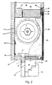
- An advantageous way of installing the invention Roller shutter box is shown in Fig. 2.
- the one in this Figure 2 shown embodiment differs in particular with regard to that in connection with FIG. 1 described positioning pin from the one described above Embodiment.
- this means Reference numeral 14 a guide rail shown here in section, for example using brackets or Screws rigidly connected to a window frame 15. On the window frame 15, a window sash 16 is pivotally mounted. Both the positioning pin protrude into the guide rail 14 1 as well as a front lip section of the guide element 5 in.
- the guide element 5 is in turn separate from the positioning pin 1 and formed over the press pin portion 6 pressed into the positioning pin 1.
- a lower outer edge area is made of insulating Material formed cover strip 17 arranged.
- the outside the shutter box or the front panel 11 is from an outer panel 18 covers.
- On the front panel 11 is a backstop device in a manner known per se 19 provided. This backstop 19 prevents a pushing up of the completely drained roller shutter from the outside.
- a fastening web 20 in the upper region of the roller shutter box trained over which the shutter box, for example can also be attached to a crossbar 21.
- another insulation element 22 provided, which is an insulation of the interior the shutter box opposite the interior of the corresponding Wall.
- an insulation molded part formed in particular from styrofoam 24 arranged in an interior wall covering 23 adjacent area is inside the roller shutter box.
- the inner wall covering 23 is suspended on a cross board 26 via a spring claw 25.
- On the cross board 26 is one with an interior plaster in particular connectable cross bar 27 attached.
- Between the Cross bar 27 and the inner wall covering 23 is one Plastic strip provided to form a parting line 28.
- one additional cross bar 29 is provided, which for example via a square slat with the inner wall cladding 23 is firmly connected.
- an insulation element connects to the inner wall cladding 23 30 on.
- This insulation element 30 is designed that this is relatively simple, in particular through a smooth cutting edge to the optimally adjusted position the positioning pin 1 is adaptable.
- the smooth cut edge either on the side of the Provide positioning pin 1 or on the inner wall paneling 23 facing side.
- the case is particularly advantageous according to the invention possible on the positioning pin 1 facing Front side of the insulation element 30 in particular from Plastic profile to put on, which in particular conveniently the space between the roller shutter and bridged the insulation element 30.
- the roller shutter shaft is further schematically shown in FIG. 2 8, which is different from the embodiment 1 is designed here as a hexagonal profile. Coaxial to this roller shutter shaft 8 is in this embodiment a belt pulley 31 is arranged on which a roller shutter belt Can be wound up and unwound to wind up and unwind the roller shutter is.
- a drive device it is also possible, for example, the roller shutter shaft 8 via a gearbox and a hand crank or via to drive a corresponding electric motor.
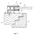
- the guide rail 14 shown in FIG. 2 is in FIG. 4 clearly shown again.
- This sectional view is the guide rail 14 via a retaining clip 32 on the Window stick 15 attached.
- This window frame 15 is in this embodiment made of wood.
- the window frame for example made of plastic or an aluminum extruded profile to manufacture.
- the guide rail 14 in one piece with the Train window frame 15.
- On the window block 15 is the Window sash 16 hinged. The one between the casement 16 and the window block 15 provided sealing device was not shown here to simplify the illustration.
- the guide rail 14 advantageously comprises two substantially rectangular inner sections.
- the left inner section is the positioning pin 1 introduced.
- the second inner section of the guide rail 14 advantageously projects a section of the Guide element 5 into it.
- Guide element designed such that this freedom of movement of sealing lamellae attached to a corresponding Inner edge portion of the guide rail 14 attached are not impaired.
- the positioning pin 1 and the guide element 5 integrally formed from a plastic material.
- roller shutter box designed according to the invention can vary depending on the type and installation position of the window resulting positions of the guide rail 14 in particular be taken into account in a simple manner without the Thickness, in particular of the outer cladding 18 (FIG. 2), is reduced should be.
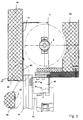
- FIG. 3 shows an alternative embodiment of the roller shutter cat shown without an adjustable positioning pin, which in each case in one piece with the respective Side cheek 2 formed fastening sections 40 in the upper lateral side area of a window frame attached is.
- Each of the attachment portions 40 is plural Provided holes 41 through which the mounting portion 40 is screwed to the window frame.
- the embodiment shown here protrudes the guide rail 14 into the interior of the roller shutter box.
- the roller shutter shaft 8 is in the embodiment shown here set such that in accordance with the embodiment Fig. 2 provided guide element 5 and on the positioning pin 1 can be dispensed with.
- Another alternative to the embodiment described in connection with Fig.2 of the roller shutter box is with the roller shutter box acc.
- a transverse profile is provided, which has a lower, a soffit surface facing a window or door reveal of the outer cladding 18.
- This cross section is via a sealing tape 43 in a sealing manner with the roller shutter box or connected to the same with a front plate 11.
- 3 aluminum blind rivets (not shown) provided which, if necessary, during assembly the roller shutter box after removing the insulation molding 24 and the roller shutter shaft 8 can be drilled.
- this blind rivet it is also possible to connect of the profile 42 with the front plate 11, for example Screws.
- the cross section 42 is dimensioned such that the distance between a front end section 42 'of the cross section 42 to one through the front plate 11 defined level on the one hand the material thickness of the outer cladding 18 corresponds, and on the other hand through this end section 42 'after placing the roller shutter box and the attached window frame on a mounting surface itself a certain distance between the window frame and the horizontal mounting surface results.
- the position of the roller shutter box 2 relative to the window frame 15 is up to Drive in or screw in the fasteners the holes 41 variable.
- window assemblies consisting of window block and roller shutter box it is possible to use the guide rail 14 provided window frame horizontally on one Lay the assembly table and the roller shutter box on the To put on the window frame. After plugging in the roller shutter box the roller shutter box on the window block Window stick attached.
- the shutter box on the window block is the Provide roller shutter box with a stop device, which preferably on an upper transverse side of the window frame sits on.
- This stop device is shown in Fig.5 Embodiment of a side cheek 2 by two notches 44 formed, which is integral with the side cheek 2nd are trained.
- the side wall 2 provided fastening section 40 with an impact claw 45, which is also in one piece is formed with the attachment portion 40.
- the positioning of the roller shutter box relative to the window frame is in the embodiment of Figure 5 by two side straps provided on the fastening section 40 46 additionally supported.
- the fastening claws 9 and the fastening section 40 through each position-controlled tools individually designed become.
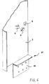
- the side cheek 2 also with a fastening section 40 provided with a triple flange with the side cheek 2 is connected.
- the triple flange 47 forms one Stop surface, which the maximum insertion depth of the Roller shutter box sets on the window stick.
- the fastening section 40 is with a number of through openings over which the fastening section 40 can be attached to the window frame.
- This one too Embodiment is the side cheek 2 with one piece therein trained fastening claws 9 provided.
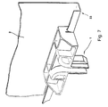
- FIG. 7 is another preferred embodiment of a Positioning pin 1 shown according to the present invention.
- the positioning pin 1 is on one formed by folding on the side cheek 2 guide rail 33 continuously adjustable. After positioning the Positioning pin at a predetermined location becomes this for example, from the outside through the Sidewall 2 attached blind rivet attached. Instead of Such a riveted joint is also possible for example by means of a punch or by training of notches on the guide rail 33 den Limit the displacement of the positioning pin.
- the positioning pin are in turn a leadership section for leadership the roller shutter and the positioning pin 1 itself in one piece educated.
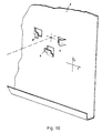
- FIG. 8 a Embodiment of the positioning pin 1 without a guide device to guide the roller shutter.
- a guide element 5 such as this is shown for example in Fig. 1, with the To connect positioning pin 1 or the guide base 3.
- Rectangular groove 34 is provided, in which the press pin section 6 (Fig. 1) of the guide element 5 (Fig. 1) can be pressed is.
- the positioning pin is also in this embodiment 1 along a guideway 33 on the side cheek 2 led.
- Clamping screw can be used for fastening the positioning pin 1 or to determine the final position of the positioning pin 1 can, for example, one not shown here Clamping screw can be used.
- the positioning pin 1 at predetermined Positions or in positions within the scope of a previous numerically controlled processing suitably trained were to attach.
- FIG. 9 A particularly favorable one with such a procedure
- the embodiment of the positioning pin is shown in FIG. 9 shown.
- the positioning pin 1 in a formed in the lower region of the side cheek 2 Punch 35 can be inserted.
- the positioning pin 1 is in this embodiment with a base portion 3a provided on which in one piece in an advantageous manner a roller shutter guide section is formed.
- This Roller shutter guide section 5a is provided with insert lips, which in the interior of the corresponding guide rail 14 (Fig. 4) protrude.
- the positioning pin 1 is advantageously off in this embodiment a plastic material, especially polyamide.
- FIG. 9 the embodiment shown in FIG.
- a position-controlled lower die 40a and an associated one Punch 41a positioned and then pressed against each other for machining the side cheek.
- the holding clips 32 are formed. More like that The way is with a position-controlled notching device 42a move through which a punch 35 is made an individually intended position is formed.
- a machining process can in particular on partially assembled roller shutter box or before assembly of the Sidewalls 2 take place.
- training appropriate to the respective requirements provided for the storage or fastening of the roller shutter shaft 8 Storage facility is also independent of the Different embodiments proposed according to the invention the positioning device applicable.
- the positioning device applicable is in the respective side cheek according to another Aspect of the present invention provided the storage device or roller shutter shaft fastening device to form on an intermediate piece, which on the side cheek slidably attached or initially pivoted on this is. Only briefly before installing the roller shutter box the position of this intermediate piece, for example fixed by screws or rivets.
- roller shutter box designed according to the invention, it is possible, for example by simply moving the positioning pin, in particular by turning an adjusting screw provided for this purpose, to merely change the position of the positioning pin and to fix the roller shutter box to its originally intended installation location without changing the outer cladding.
- the roller shutter box is fastened or installed in the wall element in an advantageous manner on the (spread out on a mounting table) Wall element.
- the wall element lies with its later outside on the assembly table.
- the roller shutter box already provided with the roller shutter is then inserted from the inside into the upper front openings of the guide rails with its positioning pins provided in pairs.
- the roller shutter box is connected to a crossbeam of the wall element, for example via slacking or the fastening web 20 shown in FIG. 2.
- the roller shutter box is advantageously completely pre-assembled and provided with the roller shutter.
- roller shutter box described above is in one large adjustment range to the respective position of the guide rail 14 adjustable, so that especially special requests regarding the window construction and window position be taken into account in a simple manner can without the insulation effect of the wall element as well to affect the statics of the wall element. Since with a and the same roller shutter box in different positions can be taken into account by guide rails, it is no longer necessary for every window type to stock a special roller shutter box.
- the invention is not based on those described above Embodiments limited.
- the position of the positioning pin essentially to change parallel to the window level.
- the roller shutter box can also store windows or doors to be attached to a blend frame.
- the invention relates generally to a roller shutter box with a shaft rotatably arranged inside, a roller shutter can be rolled up or down by its rotation is arranged in the region of the ends of the shaft Bearing device for the rotatable mounting of the shaft, and in both side areas of the roller shutter box near the Storage facility arranged roller shutter box side panels.
- the roller shutter box is characterized on the one hand in that A positioning device in the lower area of the roller shutter box is provided to determine the position of the Roller shutter box relative to a window block, in particular to a guide device for guiding the roller shutter, wherein the side cheeks are provided with fastening sections over which the roller shutter box on the window block is attachable.
- the invention further relates to a roller shutter box, at which the position of the positioning device relative to the roller shutter box according to the position a guide rail can be fixed. Furthermore relates the invention relates to a manufacturing method Manufacture of a corresponding roller shutter box and in general on a roller shutter box, in which the position the shaft inside the roller shutter box with regard to the Position of the guide rail can be optimally determined.
Landscapes
- Engineering & Computer Science (AREA)
- Structural Engineering (AREA)
- Architecture (AREA)
- Civil Engineering (AREA)
- Operating, Guiding And Securing Of Roll- Type Closing Members (AREA)
- Registering, Tensioning, Guiding Webs, And Rollers Therefor (AREA)
- Auxiliary Devices For And Details Of Packaging Control (AREA)
- Cartons (AREA)
- Vehicle Step Arrangements And Article Storage (AREA)
Description
- Fig. 1
- eine perspektivische Detailansicht eines Seitenbereiches eines Rolladenkastens gemäß einer ersten Ausführungsform der vorliegenden Erfindung,
- Fig. 2
- eine vereinfachte Schnittansicht zur Darstellung der Einbauposition eines Rolladenkastens gemäß der vorliegenden Erfindung in einer Hauswand,
- Fig. 3
- eine Schnittansicht zur Darstellung eines, über Befestigungsabschnitte an einem Fensterstock befestigten Rolladenkastens gemäß einer zweiten, alternativen Ausführungsform der Erfindung,
- Fig. 4
- eine Schnittansicht durch einen Fensterstock nebst darauf aufgesetzter Führungsschiene,
- Fig. 5
- eine perspektivische Detailansicht einer zu Befestigung an einem Fensterstock vorgesehenen Seitenwange,
- Fig. 6
- eine weitere perspektivische Detailansicht einer alternativen Ausführungsform einer zur Befestigung an einem Seitenbereich eines Fensterstockes vorgesehenen Seitenwange,
- Fig. 7
- eine perspektivische Detailansicht eines Positionierzapfens gemäß einer zweiten Ausführungsform der vorliegenden Erfindung,
- Fig. 8
- eine weitere perspektivische Detailansicht einer dritten Ausführungsform eines Positionierzapfens gemäß der vorliegenden Erfindung,
- Fig. 9
- eine perspektivische Detailansicht einer vierten Ausführungsform eines einsteckbar befestigbaren Positionierzapfens,
- Fig.10
- eine perspektivische Detailansicht eines an einer Seitenwange ausgebildeten Befestigungsabschnittes zur Befestigung einer Wellenlagerungseinrichtung.
- Fig.11
- eine Schemadarstellung zur Verdeutlichung eines erfindungsgemäßen Fertigungsabschnittes.
Wandelement. Das Wandelement liegt dabei mit seiner späteren Außenseite auf dem Montagetisch auf. Der bereits mit dem Rolladen versehene Rolladenkasten wird anschließend von innen in die oberen stirnseitigen öffnungen der Führungsschienen mit seinen paarweise vorgesehenen Positionierzapfen eingesteckt. Dadurch ist bereits die relative Position zwischen dem Rolladenkasten und dem Fenster exakt festgelegt. Nachfolgend wird der Rolladenkasten beispielsweise über Schlaudern oder den in Fig. 2 gezeigten Befestigungssteg 20 mit einem Querbalken des Wandelementes verbunden. Der Rolladenkasten ist in vorteilhafter Weise bereits vollständig vormontiert und mit dem Rolladen versehen.
Claims (15)
- Rolladenkasten mit einer in dessen Inneren drehbar angeordneten Welle (8), durch deren Drehung ein Rolladen (33) auf- oder abwickelbar ist, je einer im Bereich der Enden der Welle (8) angeordneten Lagereinrichtung zur drehbewegbaren Lagerung der Welle (8), sowie in beiden Seitenbereichen des Rolladenkastens nahe der Lagereinrichtung angeordneten Rolladenkasten-Seitenwangen (2), wobei im unteren Bereich des Rolladenkastens eine Positioniereinrichtung vorgesehen ist zur Festlegung der Position des Rolladenkastens relativ zu einem Fenster- bzw. Türstock (15), dadurch gekennzeichnet, daß die Positioniereinrichtung ein hinsischtlich seiner Position einstellbares Positionierelement (1) umfaßt, das separat vor der jeweiligen Seitenwange ausgebildet ist zur einstellbaren Positionierung des Rolladenkastens relativ zu dem Fenster- bzw. Türstock (15).
- Rolladenkasten nach Anspruch 1, dadurch gekennzeichnet, daß die Positioniereinrichtung einen Befestigungsabschnitt (40) umfaßt, über welchen der Rolladenkasten an einem Seitenbereich des Fenster- bzw. Türstocks befestigbar ist.
- Rolladenkasten nach Anspruch 1 oder 2, dadurch gekennzeichnet, daß der Befestigungsabschnitt (40) einstückig mit der Seitenwange (2) des Rolladenkastens ausgebildet ist.
- Rolladenkasten nach einem der Ansprüche 1 bis 3, dadurch gekennzeichnet, daß die Positioniereinrichtung einen Anschlagabschnitt aufweist, welcher in Einbauposition auf dem Fenster- bzw. Türstock aufsitzt, zur Festlegung der Position des Rolladenkastens relativ zu dem Fenster- bzw. Türstock in vertikaler Richtung.
- Rolladenkasten nach einem der Ansprüche 1 bis 4, dadurch gekennzeichnet, daß das Positionierelement als Positionierzapfen (1) ausgebildet ist, der mit der jeweiligen Führungsschiene (14) in Eingriff bringbar ist, insbesondere in diese einsteckbar ist.
- Rolladenkasten nach mindestens einem der Ansprüche 1 bis 5, dadurch gekennzeichnet, daß die Positionierzapfen (1) relativ zu den Seitenwangen (2) bewegbar, insbesondere verschiebbar, angeordnet sind.
- Rolladenkasten nach mindestens einem der Ansprüche 1 bis 6, dadurch gekennzeichnet, daß eine Fixiereinrichtung vorgesehen ist, zur Fixierung des Positionierzapfens (1) in einer vorbestimmten Position.
- Rolladenkasten nach mindestens einem der Ansprüche 1 bis 7, dadurch gekennzeichnet, daß eine Stellschraubeneinrichtung vorgesehen ist, zur Bewegung des Positionierzapfens (1).
- Rolladenkasten nach Anspruch 1, dadurch gekennzeichnet, daß die Positioniereinrichtung eine im unteren Bereich der Seitenwange (2) vorgesehene Positionier-Ausformung, insbesondere Ausstanzung (35) umfaßt.
- Rolladenkasten nach mindestens einem der Ansprüche 1 bis 9, dadurch gekennzeichnet, daß die Position einer Lagereinrichtung zur drehbewegbaren Lagerung der Welle (8) bedarfsgerecht festlegbar ist.
- Rolladenkasten nach mindestens einem der Ansprüche 1 bis 10, dadurch gekennzeichnet, daß die Position einer zur Halterung der Lagereinrichtung vorgesehenen Befestigungseinrichtung durch ein positionsgesteuertes Werkzeug festgelegt wird.
- Rolladenkasten nach mindestens einem der Ansprüche 1 bis 11, dadurch gekennzeichnet, daß die Position einer zur Aufnahme des Positionierzapfens (1) vorgesehenen Ausformung durch ein weggesteuertes Werkzeug festgelegt ist.
- Verfahren zur Herstellung eines Rolladenkastens, bei welchem im Rahmem eines Montageschrittes ein Paar von Seitenwangen an Längs-Endabschnitten des Rolladenkastens angebracht werden, dadurch gekennzeichnet, daß im Rahmen eines computergesteuerten Bearbeitungsvorganges ein Positionsdatensatz an eine Bearbeitungsschiene zur Bearbeitung der Seitenwangen übergeben wird und daß entsprechend der übergebenen Positionsdaten eine Umformumg der Seitenwangen erfolgt, wobei durch die Umformung eine Ausformung zur Festlegung der Position eines Positionierzapfens, eines Befestigungsabschnittes (40), oder der Position der Wellenlagerung erzeugt wird.
- Verfahren nach Anspruch 13, dadurch gekennzeichnet, daß die Umformung im Rahmen eines Stanz-Biegevorganges erfolgt.
- Verfahren nach Anspruch 13 oder 14, dadurch gekennzeichnet, daß die Umformung nach Anbringung der Seitenwangen an dem Rolladenkasten erfolgt.
Applications Claiming Priority (3)
| Application Number | Priority Date | Filing Date | Title |
|---|---|---|---|
| DE19521752A DE19521752A1 (de) | 1995-06-14 | 1995-06-14 | Rolladenkasten |
| DE19521752 | 1995-06-14 | ||
| PCT/EP1996/002564 WO1997000367A1 (de) | 1995-06-14 | 1996-06-14 | Rolladenkasten |
Publications (2)
| Publication Number | Publication Date |
|---|---|
| EP0832342A1 EP0832342A1 (de) | 1998-04-01 |
| EP0832342B1 true EP0832342B1 (de) | 1999-02-03 |
Family
ID=7764421
Family Applications (1)
| Application Number | Title | Priority Date | Filing Date |
|---|---|---|---|
| EP96918691A Expired - Lifetime EP0832342B1 (de) | 1995-06-14 | 1996-06-14 | Rolladenkasten |
Country Status (4)
| Country | Link |
|---|---|
| EP (1) | EP0832342B1 (de) |
| AT (1) | ATE176515T1 (de) |
| DE (2) | DE19521752A1 (de) |
| WO (1) | WO1997000367A1 (de) |
Families Citing this family (17)
| Publication number | Priority date | Publication date | Assignee | Title |
|---|---|---|---|---|
| GB9616536D0 (en) | 1996-08-06 | 1996-09-25 | Quadrant Holdings Cambridge | Co-amoxiclav dosage form |
| FR2785940B1 (fr) * | 1998-11-18 | 2001-01-12 | Carretier & Robin Sa Ets | Agencement decale de la pente de passage et des coulisses d'un volet roulant a tablier a lames |
| DE19930785B4 (de) * | 1999-07-03 | 2005-04-07 | Reflexa-Werke Albrecht Gmbh | Rolladen, insbesondere Trapezrolladen |
| DE10003181B4 (de) * | 2000-01-25 | 2004-10-07 | Roma Rolladensysteme Gmbh | Vorrichtung zum Verschließen einer Bauwerksöffnung |
| FR2809761B1 (fr) * | 2000-05-31 | 2002-12-13 | Simbac S P A | Dispositif formant support d'extremite pour un arbre d'enroulement, son procede d'assemblage et mecanisme de manoeuvre d'une installation de fermeture ou de protection solaire comprenant un tel dispositif |
| DE10135655C2 (de) * | 2001-07-21 | 2003-05-28 | Sks Stakusit Bautechnik Gmbh | Rollladenkasten |
| EP1811120B1 (de) * | 2006-01-19 | 2011-08-10 | Veka AG | Rollladenkasten zum Aufsetzen auf einen Blendrahmen |
| DE102009019985B4 (de) | 2008-10-22 | 2019-04-18 | A.R.T. Systemtechnik GmbH & Co. KG | System zum Aufrollen von Verschlüssen für Gebäudeöffnungen |
| DE102009020334A1 (de) * | 2008-12-11 | 2010-06-17 | Alfred Schellenberg Gmbh | Bausatz zur Erstellung eines Vorbau-Rollladens zum Schutz von Öffnungen, insbesondere von Fenstern, Türen o. dgl., sowie Vorbau-Rollladen aus dem Bausatz |
| DE202009006640U1 (de) * | 2009-05-07 | 2009-07-23 | Alfred Schellenberg Gmbh | Vorbau-Rollladen zum Schutz von Öffnungen, insbesondere von Fenstern, Türen o.dgl. |
| DE102010000155A1 (de) | 2010-01-21 | 2011-07-28 | EXTE-Extrudertechnik GmbH, 51688 | Rollladenkasten |
| DE102011103478A1 (de) * | 2011-06-03 | 2012-12-06 | Multifilm Sonnen- Und Blendschutz Gmbh | Rollobaugruppe mit einem Rollokasten, Haltebauteil zum Halten eines Rollokastens sowie Lagerschild |
| FR2982313B1 (fr) * | 2011-11-04 | 2013-12-27 | Production De Portes Et Fermetures Soc D | Coffre pour volet roulant, avec organes lateraux de guidage formant tulipes |
| DE102014001636B4 (de) * | 2014-02-07 | 2023-07-20 | D&M Kg | Wandaufbau in Verbindung mit einem Tür- oder Fensterrahmen und eine energieeffiziente Einbauanordnung mit einem Kastenelement |
| DE102015200487B4 (de) | 2015-01-14 | 2022-08-25 | FEMA GmbH & Co. KG | Lagerhalter zur Aufnahme eines Lagers für eine Rollladenwelle und Lageranordnung |
| DE202016105520U1 (de) * | 2016-10-05 | 2017-01-12 | Nordic Door Ab | Rolltor |
| DE102024110904A1 (de) * | 2024-04-18 | 2025-10-23 | Reiner Detenhoff | Rollabschlusssystem und Verfahren zum Aufrichten eines Rollabschlusssystems |
Family Cites Families (9)
| Publication number | Priority date | Publication date | Assignee | Title |
|---|---|---|---|---|
| US1810849A (en) * | 1929-07-22 | 1931-06-16 | Alvin F Nye | Roller screen mounting |
| LU51040A1 (de) * | 1965-05-07 | 1966-07-05 | ||
| BE772321Q (de) * | 1968-08-09 | 1972-01-17 | Goetze Rollofab Carl | |
| DE2824301C2 (de) * | 1978-06-02 | 1982-08-12 | Reinhold Kittelberger u. Söhne oHG, 7140 Ludwigsburg | Vorrichtung zum Verbinden eines Fensterblend- oder eines Türrahmens mit einem Rolladenkasten |
| DE3419206C2 (de) * | 1984-05-23 | 1993-10-21 | Joma Daemmstoffwerk Josef Mang | Rolladenkasten |
| DE3443931A1 (de) * | 1984-12-01 | 1986-06-05 | Armin 4630 Bochum Besler | Aussenrolladen und verfahren zu seiner montage |
| DE8901481U1 (de) * | 1989-02-09 | 1989-04-06 | Stakusit-Stahl-Kunststoff GmbH, 4100 Duisburg | Rolladenkasten |
| DE4128194C2 (de) * | 1991-08-24 | 1994-05-19 | Rohde & Schwarz | Vorrichtung zum automatischen Herstellen von Blechteilen |
| DE29509573U1 (de) * | 1995-06-10 | 1995-08-24 | Lemke, Hartmut, 79117 Freiburg | Vorrichtung zum Befestigen eines Fensterrahmens an einem Rolladenkasten |
-
1995
- 1995-06-14 DE DE19521752A patent/DE19521752A1/de not_active Withdrawn
-
1996
- 1996-06-14 EP EP96918691A patent/EP0832342B1/de not_active Expired - Lifetime
- 1996-06-14 AT AT96918691T patent/ATE176515T1/de not_active IP Right Cessation
- 1996-06-14 WO PCT/EP1996/002564 patent/WO1997000367A1/de not_active Ceased
- 1996-06-14 DE DE59601274T patent/DE59601274D1/de not_active Expired - Fee Related
Also Published As
| Publication number | Publication date |
|---|---|
| DE19521752A1 (de) | 1996-12-19 |
| WO1997000367A1 (de) | 1997-01-03 |
| ATE176515T1 (de) | 1999-02-15 |
| EP0832342A1 (de) | 1998-04-01 |
| DE59601274D1 (de) | 1999-03-18 |
Similar Documents
| Publication | Publication Date | Title |
|---|---|---|
| DE69705662T2 (de) | Rollvorrichtung für Schiebetüren, Fenster oder ähnliches | |
| EP1690711B1 (de) | Fensterrollo mit vereinfachter Montage | |
| EP1216866B1 (de) | Leichtbautür für Kraftfahrzeuge | |
| EP2060421B1 (de) | Rolloanordnung mit verminderter Reibung im Antrieb | |
| EP0832342A1 (de) | Rolladenkasten | |
| EP1835113A2 (de) | Einstellbarer Fensterheber | |
| EP2985404B1 (de) | Rollladenkasten | |
| AT404380B (de) | Vorrichtung, insbesondere distanzanker für justierung und befestigung von rahmen | |
| DE68902221T2 (de) | Verfahren und streifen zum herstellen einer u-foermigen fuehrung in einer nute eines fensterrahmens. | |
| EP3705676B1 (de) | Verfahren zur montage eines rollladenkastens und auf einem rahmenteil aufgesetzter rollladenkasten | |
| EP3071896B1 (de) | Haltevorrichtung für ein gehäuse und verfahren zur montage des gehäuses unter verwendung der haltevorrichtung | |
| DE10301661B4 (de) | Montagebaueinheit zum Befestigen einer Sonnenblende | |
| DE102006002406A1 (de) | Türmodul für eine Fahrzeugtür, Fahrzeugtür mit einem Türmodul sowie Verfahren zur Montage eines Türmoduls an einer Fahrzeugtür | |
| DE10163203C5 (de) | Rolloanordnung für ein Kraftfahrzeug-Seitentürfenster | |
| DE69821874T2 (de) | Tragevorrichtung für Rolläden, insbesondere für traditionelle Anwendungen | |
| DE4439394C2 (de) | Trag- und Befestigungsvorrichtung für einen Rolladenkasten | |
| DE102009054644B4 (de) | Beschlagteilanordnung für ein Fenster, eine Tür, eine Klappe oder dergleichen | |
| AT520997B1 (de) | Montagehalter | |
| DE2810981C2 (de) | Vorrichtung zur Befestigung einer Zarge | |
| DE69800458T2 (de) | Stangenaustrittsführung für Treibstangen oder Treibstangenschloss | |
| DE19734647B4 (de) | Beschlagteil an einem Flügel oder einem festen Rahmen eines Fensters, einer Tür od. dgl. | |
| EP2369118B1 (de) | Rollladenkasten sowie Isolationsteil für einen Rollladenkasten | |
| EP2050893A2 (de) | Verkleidungselement für Fassadenverkleidung von Gebäuden | |
| DE10145052B4 (de) | Satz von Innenfutterprofilleisten | |
| DE10154477A1 (de) | Kupplungsvorrichtung |
Legal Events
| Date | Code | Title | Description |
|---|---|---|---|
| PUAI | Public reference made under article 153(3) epc to a published international application that has entered the european phase |
Free format text: ORIGINAL CODE: 0009012 |
|
| 17P | Request for examination filed |
Effective date: 19971212 |
|
| AK | Designated contracting states |
Kind code of ref document: A1 Designated state(s): AT DE |
|
| GRAG | Despatch of communication of intention to grant |
Free format text: ORIGINAL CODE: EPIDOS AGRA |
|
| 17Q | First examination report despatched |
Effective date: 19980714 |
|
| GRAG | Despatch of communication of intention to grant |
Free format text: ORIGINAL CODE: EPIDOS AGRA |
|
| GRAH | Despatch of communication of intention to grant a patent |
Free format text: ORIGINAL CODE: EPIDOS IGRA |
|
| GRAH | Despatch of communication of intention to grant a patent |
Free format text: ORIGINAL CODE: EPIDOS IGRA |
|
| GRAA | (expected) grant |
Free format text: ORIGINAL CODE: 0009210 |
|
| AK | Designated contracting states |
Kind code of ref document: B1 Designated state(s): AT DE |
|
| REF | Corresponds to: |
Ref document number: 176515 Country of ref document: AT Date of ref document: 19990215 Kind code of ref document: T |
|
| REF | Corresponds to: |
Ref document number: 59601274 Country of ref document: DE Date of ref document: 19990318 |
|
| PLBE | No opposition filed within time limit |
Free format text: ORIGINAL CODE: 0009261 |
|
| STAA | Information on the status of an ep patent application or granted ep patent |
Free format text: STATUS: NO OPPOSITION FILED WITHIN TIME LIMIT |
|
| 26N | No opposition filed | ||
| PGFP | Annual fee paid to national office [announced via postgrant information from national office to epo] |
Ref country code: AT Payment date: 20030623 Year of fee payment: 8 |
|
| PGFP | Annual fee paid to national office [announced via postgrant information from national office to epo] |
Ref country code: DE Payment date: 20030730 Year of fee payment: 8 |
|
| PG25 | Lapsed in a contracting state [announced via postgrant information from national office to epo] |
Ref country code: AT Free format text: LAPSE BECAUSE OF NON-PAYMENT OF DUE FEES Effective date: 20040614 |
|
| PG25 | Lapsed in a contracting state [announced via postgrant information from national office to epo] |
Ref country code: DE Free format text: LAPSE BECAUSE OF NON-PAYMENT OF DUE FEES Effective date: 20050101 |