EP0831568B1 - Frequenz-Getrenntlagelaser mit zwei harmonischen Wellenlängen - Google Patents
Frequenz-Getrenntlagelaser mit zwei harmonischen Wellenlängen Download PDFInfo
- Publication number
- EP0831568B1 EP0831568B1 EP97306896A EP97306896A EP0831568B1 EP 0831568 B1 EP0831568 B1 EP 0831568B1 EP 97306896 A EP97306896 A EP 97306896A EP 97306896 A EP97306896 A EP 97306896A EP 0831568 B1 EP0831568 B1 EP 0831568B1
- Authority
- EP
- European Patent Office
- Prior art keywords
- laser
- crystal
- doubling
- gain medium
- quarter wave
- Prior art date
- Legal status (The legal status is an assumption and is not a legal conclusion. Google has not performed a legal analysis and makes no representation as to the accuracy of the status listed.)
- Expired - Lifetime
Links
- 230000009977 dual effect Effects 0.000 title 1
- 239000013078 crystal Substances 0.000 claims description 64
- 230000003287 optical effect Effects 0.000 claims description 34
- 230000010287 polarization Effects 0.000 claims description 24
- 239000000835 fiber Substances 0.000 claims description 7
- VCZFPTGOQQOZGI-UHFFFAOYSA-N lithium bis(oxoboranyloxy)borinate Chemical compound [Li+].[O-]B(OB=O)OB=O VCZFPTGOQQOZGI-UHFFFAOYSA-N 0.000 claims description 4
- 239000004065 semiconductor Substances 0.000 claims description 4
- GQYHUHYESMUTHG-UHFFFAOYSA-N lithium niobate Chemical compound [Li+].[O-][Nb](=O)=O GQYHUHYESMUTHG-UHFFFAOYSA-N 0.000 claims description 2
- 239000002223 garnet Substances 0.000 claims 1
- 239000013307 optical fiber Substances 0.000 claims 1
- 229910052727 yttrium Inorganic materials 0.000 claims 1
- VWQVUPCCIRVNHF-UHFFFAOYSA-N yttrium atom Chemical compound [Y] VWQVUPCCIRVNHF-UHFFFAOYSA-N 0.000 claims 1
- 238000005259 measurement Methods 0.000 description 25
- 239000013598 vector Substances 0.000 description 16
- 238000000034 method Methods 0.000 description 12
- 238000005305 interferometry Methods 0.000 description 7
- 238000006243 chemical reaction Methods 0.000 description 5
- 230000008878 coupling Effects 0.000 description 5
- 238000010168 coupling process Methods 0.000 description 5
- 238000005859 coupling reaction Methods 0.000 description 5
- 230000000694 effects Effects 0.000 description 4
- 238000012937 correction Methods 0.000 description 3
- 239000006185 dispersion Substances 0.000 description 3
- 238000010521 absorption reaction Methods 0.000 description 2
- 238000000576 coating method Methods 0.000 description 2
- 239000002019 doping agent Substances 0.000 description 2
- 230000003993 interaction Effects 0.000 description 2
- 238000004519 manufacturing process Methods 0.000 description 2
- 239000000463 material Substances 0.000 description 2
- 238000000926 separation method Methods 0.000 description 2
- 238000002834 transmittance Methods 0.000 description 2
- 229910052691 Erbium Inorganic materials 0.000 description 1
- 229910003327 LiNbO3 Inorganic materials 0.000 description 1
- 229910052777 Praseodymium Inorganic materials 0.000 description 1
- BJQHLKABXJIVAM-UHFFFAOYSA-N bis(2-ethylhexyl) phthalate Chemical compound CCCCC(CC)COC(=O)C1=CC=CC=C1C(=O)OCC(CC)CCCC BJQHLKABXJIVAM-UHFFFAOYSA-N 0.000 description 1
- 238000004891 communication Methods 0.000 description 1
- 230000001419 dependent effect Effects 0.000 description 1
- 238000006073 displacement reaction Methods 0.000 description 1
- 238000004134 energy conservation Methods 0.000 description 1
- UYAHIZSMUZPPFV-UHFFFAOYSA-N erbium Chemical compound [Er] UYAHIZSMUZPPFV-UHFFFAOYSA-N 0.000 description 1
- 239000003365 glass fiber Substances 0.000 description 1
- 239000012535 impurity Substances 0.000 description 1
- 238000002347 injection Methods 0.000 description 1
- 239000007924 injection Substances 0.000 description 1
- 239000011159 matrix material Substances 0.000 description 1
- PUDIUYLPXJFUGB-UHFFFAOYSA-N praseodymium atom Chemical compound [Pr] PUDIUYLPXJFUGB-UHFFFAOYSA-N 0.000 description 1
- 238000012545 processing Methods 0.000 description 1
- 230000003595 spectral effect Effects 0.000 description 1
- 238000004611 spectroscopical analysis Methods 0.000 description 1
- 238000001228 spectrum Methods 0.000 description 1
- 230000006641 stabilisation Effects 0.000 description 1
- 238000011105 stabilization Methods 0.000 description 1
- 239000000758 substrate Substances 0.000 description 1
Images


Classifications
-
- H—ELECTRICITY
- H01—ELECTRIC ELEMENTS
- H01S—DEVICES USING THE PROCESS OF LIGHT AMPLIFICATION BY STIMULATED EMISSION OF RADIATION [LASER] TO AMPLIFY OR GENERATE LIGHT; DEVICES USING STIMULATED EMISSION OF ELECTROMAGNETIC RADIATION IN WAVE RANGES OTHER THAN OPTICAL
- H01S3/00—Lasers, i.e. devices using stimulated emission of electromagnetic radiation in the infrared, visible or ultraviolet wave range
- H01S3/10—Controlling the intensity, frequency, phase, polarisation or direction of the emitted radiation, e.g. switching, gating, modulating or demodulating
- H01S3/106—Controlling the intensity, frequency, phase, polarisation or direction of the emitted radiation, e.g. switching, gating, modulating or demodulating by controlling devices placed within the cavity
- H01S3/108—Controlling the intensity, frequency, phase, polarisation or direction of the emitted radiation, e.g. switching, gating, modulating or demodulating by controlling devices placed within the cavity using non-linear optical devices, e.g. exhibiting Brillouin or Raman scattering
- H01S3/109—Frequency multiplication, e.g. harmonic generation
-
- G—PHYSICS
- G01—MEASURING; TESTING
- G01B—MEASURING LENGTH, THICKNESS OR SIMILAR LINEAR DIMENSIONS; MEASURING ANGLES; MEASURING AREAS; MEASURING IRREGULARITIES OF SURFACES OR CONTOURS
- G01B9/00—Measuring instruments characterised by the use of optical techniques
- G01B9/02—Interferometers
- G01B9/02001—Interferometers characterised by controlling or generating intrinsic radiation properties
- G01B9/02007—Two or more frequencies or sources used for interferometric measurement
-
- G—PHYSICS
- G01—MEASURING; TESTING
- G01B—MEASURING LENGTH, THICKNESS OR SIMILAR LINEAR DIMENSIONS; MEASURING ANGLES; MEASURING AREAS; MEASURING IRREGULARITIES OF SURFACES OR CONTOURS
- G01B2290/00—Aspects of interferometers not specifically covered by any group under G01B9/02
- G01B2290/70—Using polarization in the interferometer
-
- H—ELECTRICITY
- H01—ELECTRIC ELEMENTS
- H01S—DEVICES USING THE PROCESS OF LIGHT AMPLIFICATION BY STIMULATED EMISSION OF RADIATION [LASER] TO AMPLIFY OR GENERATE LIGHT; DEVICES USING STIMULATED EMISSION OF ELECTROMAGNETIC RADIATION IN WAVE RANGES OTHER THAN OPTICAL
- H01S3/00—Lasers, i.e. devices using stimulated emission of electromagnetic radiation in the infrared, visible or ultraviolet wave range
- H01S3/05—Construction or shape of optical resonators; Accommodation of active medium therein; Shape of active medium
- H01S3/08—Construction or shape of optical resonators or components thereof
- H01S3/08086—Multiple-wavelength emission
- H01S3/0809—Two-wavelenghth emission
Definitions
- the present invention is directed towards the field of interferometry, in particular, the area of distance-measuring interferometry.
- Interference phenomena with laser beams is used to make highly accurate displacement measurements, such as in the control of wafer steppers used in integrated circuit (IC) manufacturing.
- IC integrated circuit
- a distance-measuring laser interferometer light from a laser source is split into two beams.
- the reference beam is reflected from a stationary reference mirror, while the measurement beam is reflected from a moving measurement mirror.
- the beams are recombined at a detector where their wavefronts interfere.
- the optical intensity of the combined wavefront depends on the differential optical length between the reference and measurement paths.
- a change in differential optical path length of ⁇ /m causes one fringe of interference, where m is the number of passes the light makes between the beam splitter and the measurement mirror.
- the change in optical intensity of the combined wavefront is converted to an electrical signal by the detector.
- the detector signal is processed to determine the total change in the optical length of the measurement path, and thus the total position change in the measurement mirror, by counting the fringes of the signal.
- DC and AC Two types of distance-measuring interferometers are: DC and AC.
- a DC interferometer the laser emits a single frequency. Only when the measurement mirror is moving is the interference signal time-varying, due to the Doppler effect. When the measurement mirror is stationary, the interference signal is a constant. Disturbances such as laser power drift and electronic noise can be easily misinterpreted as a motion signal, especially when the measurement mirror is stationary.
- an AC interferometer the laser emits two optical frequencies with orthogonal polarizations. The frequencies are separated with a polarization-dependent beam splitter, with one frequency going to the reference mirror and the other going to the measurement mirror.
- the detector generates an AC signal when the measurement mirror is stationary as well as when it is moving. It is easier to retect noise with a time-varying signal than with a constant one. Therefore, AC interferometry is more accurate than DC due to its superior ability to reject noise.
- n(z) is the index of refraction of the ambient medium (usually air) expressed as a function of position
- n the value averaged along the measurement path.
- the laser interferometer measurement must be corrected for the refractive index of air, which is assumed to be spatially constant.
- the air along the measurement path may be turbulent, particularly in the region surrounding the wafer stage of a stepper. Air turbulence can lead to serious position-measurement errors as the feature sizes of ICs shrink.
- the quantity ⁇ (r) is the local air density expressed as a function of position.
- the optical path length is measured at two widely-separated wavelengths: ⁇ 1 and ⁇ 2 , where the index of refraction is different due to dispersion. These measurements relate the geometrical distance d to the air density averaged over the measurement path ⁇ , as shown in Equations 3a and 3b:.
- Equations 3a and 3b become: and where F 1 and F 2 are the fringe counts that are generated by processing the interference signals at wavelengths ⁇ 1 and ⁇ 2 , respectively.
- the factor in square brackets represents the first-order estimate of the geometrical length. To ensure accuracy, the wavelength ⁇ 1 must be accurately known.
- the wavelength ratio ⁇ 1 / ⁇ 2 must be accurately known.
- One way is for the wavelengths to be harmonically related. For example, if ⁇ 2 is the second-harmonic wavelength of ⁇ 1 , then the wavelength ratio is identically equal to 2.
- the optical path length is independently measured at three wavelengths: ⁇ m , ⁇ c1 , and ⁇ c2 .
- the measurement wavelength ⁇ m is derived from a HeNe laser and is accurately known.
- the correction wavelengths ⁇ c1 and ⁇ c2 are harmonically related and are generated from a Nd:YAG laser.
- Sommargren in U.S.P.N. 4,684,828, used a single frequency, linearly polarized laser beam to achieve a high efficiency beam with two, orthogonally polarized frequencies.
- a frequency split of several MHz is required at each wavelength.
- Using an acousto-optic modulator (AOM) provides a frequency shift of several tens of MHz to ⁇ 100 MHz.
- AOMs driven at different RF frequencies must be used at each wavelength, their frequency difference giving the desired splitting. The cost, space, and opto-mechanical complexity required is considerable.
- a laser that simultaneously generates two overlapping beams at harmonically-related wavelengths, with a frequency splitting of several MHz between orthogonal-polarizations at each wavelength is desirable.
- the laser produces a pair of orthogonally polarized frequencies with a frequency split adjustable over the range of ⁇ 0.5 - 20 MHz to facilitate AC interferometry with a variety of measurement-mirror velocities.
- a laser in a twisted mode configuration includes two non-linear crystals for intra cavity frequency doubling. Two doubling crystal stages are positioned in series between an output mirror and a first quarter waveplate. A gain medium is positioned between the first quarter waveplate and a second quarter waveplate. A mirror is positioned between the second quarter waveplate and coupling optics. The gain medium is further coupled to a pump source.
- Figure 1 illustrates a prior art twisted mode laser.
- Figure 2 illustrates a laser of the present invention.
- Figures 3A and 3B illustrates collinear and non-collinear phase matching.
- Figure 4 illustrates the eigenpolarizations.
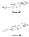
- FIGS 5A and 5B illustrate Type I phasematching.
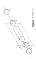
- Figure 6 illustrates the doubling stage shown in Figure 2.
- FIG. 7 illustrates "walk-off'.
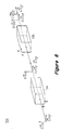
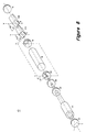
- Figure 8 illustrates another embodiment of Figure 2.
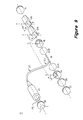
- Figure 9 illustrates another embodiment of Figure 2.
- Figure 10 illustrates another embodiment of Figure 2.
- Figure 1 illustrates a prior art twisted mode laser.
- the quarter wave plates (QWPs) are rotated about the optical axis of the cavity so that their fast axes are offset by an angle ⁇ .
- the laser may oscillate at multiple wavelengths within the bandwidth of the gain medium provided that the optical frequencies coincide to the axial mode spectrum of the cavity.
- the laser has two sets of axial mode frequencies: ⁇ + q and ⁇ + q
- c/2L 1.5 GHz.
- the polarizations of the 2 sets of modes are shown to be orthogonally polarized with respect to each other.
- one set of modes (the "+” set) is right circularly polarized (rcp) traveling to the right and left circularly polarized (lcp) traveling to the left.
- the other set of modes (the "-" set) is lcp traveling to the right and rcp traveling to the left.
- the two sets of modes are linearly polarized at 90° to each other and at ⁇ 45° with respect to the fast axis of the adjacent QWP.
- One method for mode control is to place a linear polarizer between one of the mirrors and the adjacent QWP in order to suppress one complete set of modes and eliminate spatial hole eburning. Between the QWPs, each mode of the surviving set would have a uniform intensity and a linear polarization that twisted in space.
- FIG. 2 illustrates a laser 10 of the present invention.
- Two doubling crystal stages 12A, 12B are positioned in series between a first mirror 14 and a first QWP 16.
- a gain medium 18 is positioned between the first QWP 16 and a second QWP 20.
- the e axis of the first doubling stage 12A being at +45° to and the e axis of the second doubling stage 12B being at -45° to the fast axis of the second QWP 20.
- Each QWP has a retardation of ⁇ /4 at the fundamental wavelength: their fast axes are rotated about the beam axis by an angle ⁇ with respect to each other.
- a pump source 30 couples energy into the gain medium 18.
- a second mirror 22 is positioned between the second QWP 20.
- a mode selector 26, is located between the second mirror 22 and the first QWP 20.
- the mode selector 26, preferably etalon, may be located anywhere within the cavity. Mode selection permits the laser to oscillate in a single pair of modes ⁇ + / q , and ⁇ - / q , with a unique value of q, that are separated by several MHz (on the order of 1-10 MHz), while suppressing all other pairs of modes that are on the order of a few GHz or more away.
- the single pair of modes are the fundamental frequencies ⁇ f1 and ⁇ f2 Birefringent filters and diffraction gratings may alternatively be used for mode selection.
- the second mirror 22 has a high reflectance at the fundamental wavelength.
- the characteristics of the first mirror 14 at the fundamental wavelength are such as to feed back most of the light (e.g. 98-99% reflectance) and also to allow a small output coupling (e.g. 1-2% transmittance)
- the second mirror has a high transmittance (e.g. >80%).
- Multi-layer dielectric coatings can be readily designed and deposited on transparent substrates to provide such spectral characteristics.
- a wavelength stabilization loop incorporating one of a number of well-known saturation spectroscopy methods, may be added to the laser.
- Optical second-harmonic generation is a special case of optical sum-frequency generation.
- one photon at frequency ⁇ 1 and one photon at frequency ⁇ 2 are annihilated while simultaneously a photon at frequency is generated at frequency ⁇ 3 .
- ⁇ 3 ⁇ 1 + ⁇ 2 Equation 13 is a statement of energy conservation for this frequency conversion process. This effect depends on very weak nonlinear optical properties of materials.
- the intensity of the generated beam at frequency ⁇ 3 is proportional to the product of the intensities of the beams at frequencies ⁇ 1 and ⁇ 2 , i.e.
- Equation 15 expresses a vector relationship.
- the vectors may either be collinearly or non-collinearly phasematched, as shown in Figures 3A and 3B, respectively.
- Collinear phase matching is preferred because the tightly focused beams to remain overlapped for long distances.
- the frequencies involved are widely separated. For example, if ⁇ f is in the near infrared, ⁇ sh is in the visible. Since the crystal must be transparent at these frequencies, its refractive index will exhibit normal dispersion, which prevents phase matching in isotropic crystals.
- Phase matching can be performed in anisotropic, birefringent crystals.
- birefringence can be used to exactly compensate the effect of dispersion, thereby meeting the phase matching condition and improving nonlinear conversion efficiencies.
- the refractive index properties of any crystal is described by the three principal indices of refraction n x , n y , and n z .
- isotropic crystals all three principal indices are equal. Otherwise the crystal is birefringent. If two principal indices are equal, the crystal is called uniaxial. When all three principal indices have different values, the crystal is called bi-axial.
- the propagation of the wavefront of an optical beam is described by the phase velocity vector and a group velocity vector.
- the group velocity vector, indicative of the direction and velocity of energy flow: v g 2 ⁇ k ⁇ (k)
- v p and v g are parallel. This is not in general the case in birefringent crystals except for certain particular directions of propagation.
- the state of polarization of an optical beam is generally not preserved as it propagates through a birefringent crystal.
- the two eigenpolarizations are called the ordinary and extraordinary polarizations, and the corresponding eigenindices are often called the ordinary index of refraction n 0 and the extraordinary index of refraction n e.
- the phase and group velocity vectors of the ordinary beam are parallel, so that it propagates as it "ordinarily” would in an isotropic crystal.
- the phase and group velocity vectors of the extraordinary beam are not in general parallel, so that it exhibits "extraordinary” properties.
- the value of n o does not depend on propagation direction whereas the value of n e does depend on propagation direction.
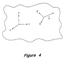
- Figure 4 illustrates the ordinary ( ô ) and extraordinary ( ê ) eigenpolarization axes for a particular arbitrarily-chosen propagation direction inside a birefringent crystal.
- n e ( ⁇ , ⁇ ) The directional dependence of the extraordinary index is expressed as n e ( ⁇ , ⁇ ), where ⁇ and ⁇ indicate the orientation of the direction of propagation with respect to the z principle axis of the crystal.
- ⁇ and ⁇ indicate the orientation of the direction of propagation with respect to the z principle axis of the crystal.
- Type 1 and Type 2 There are two commonly used techniques for utilizing the eigenpolarization states of a birefringent crystal to satisfy the phase matching condition required in order to achieve efficient second harmonic generation.
- Type 1 phase matching the fundamental and second harmonic beams are orthogonally polarized while in Type 2, their polarizations are not orthogonal.
- Type 1 phase matching is desirable because it is desirable for the polarizations of the k 1 and k 2 fundamental beams to be identical and oriented in either the ordinary or extraordinary directions, while the generated second harmonic beam has the orthogonal polarization to the fundamental beams (either, extraordinary or ordinary, respectively).
- ooe Type 1 phase matching.
- the invention orients the eigenpolarization directions of pairs of intra cavity Type 1 doubling crystals relative to the orthogonal linear polarizations of the fundamental beams so that only the second harmonic frequencies will be generated.
- FIG 6 illustrates the doubling crystal stages 12A, 12B shown in Figure 2.
- Two doubling crystals 12A, 12B are positioned one behind the other along the path of the fundamental beams.
- Each doubling crystal stage 12A, 12B includes one or more Type 1 second harmonic crystals, such as magnesium-oxide-doped lithium niobate (MgO:LiNbO 3 ) or lithium triborate (LBO) which exhibits "walkoff".
- Type 1 second harmonic crystals such as magnesium-oxide-doped lithium niobate (MgO:LiNbO 3 ) or lithium triborate (LBO) which exhibits "walkoff".
- the crystals have negative birefringence (ooe phase matching)
- the order in which the second harmonics are generated and the directions of their polarizations are reversed.
- Figure 6 illustrates the "eeo" configuration of field polarizations and crystal orientations.
- the group velocity vector v ge of the extraordinary beam is not parallel to the group velocity vector v go of the ordinary beam except for certain particular directions of the wave vector in the crystal.
- This non-collinearity causes double refraction in crystal optics.
- the ordinary and extraordinary beams are angularly divergent inside the crystal. As they undergo refraction upon exiting the crystal, they become parallel but laterally offset.
- Type 1 harmonic generation the effect leads to the angular divergence p of the fundamental and second harmonic beams inside the crystal and is called walkoff. If walk off is present, the fundamental and second harmonic beams exiting will be laterally offset. Walkoff reduces the second harmonic conversion efficiency because the distance over which the beams remain overlapped is reduced.
- a doubling stage may include a series of pairs of doubling crystals.
- FIG 8 illustrates a variation of Figure 2.
- the gain medium 18 is a Nd:YAG crystal having polarization-independent gain and which is oriented so that it is non-birefringent for light traveling in the direction of the intra cavity beam.
- the Nd:YAG is optically pumped in an axial configuration by a pump laser diode 30 whose emission wavelength overlaps the absorption band ofNd:YAG at 808 nm.
- the pump light is focused into the Nd:YAG crystal through the second mirror, mode selector, and second QWP by a coupling optical system 24 containing components such as lenses and prisms.
- the second mirror 22 is highly reflecting at the Nd:YAG fundamental wavelength of 1064 nm and highly transmitting at the pump wavelength of 808 nm.
- Figure 9 illustrates another variation of Figure 2.
- a glass fiber optical gain medium acts as the gain medium 18.
- the fiber is doped with a lasing impurity, such as Erbium or Praseodymium. Other dopants may be used to obtain a variety of fundamental wavelengths.
- the fiber gain medium is pumped by a laser diode 30 with a pump wavelength appropriate for the absorption band of the dopant material.
- the pump light is focused into a section of fiber 32 with a coupling optical system.
- the pump fiber 32 is spliced to the fiber amplifier with a dichroic fiber coupler 33. Since the gain medium is a waveguide, a first and a second intra cavity lens 34A, 34B are used to couple the light at the fundamental into and out of the waveguide.
- FIG 10 illustrates another variation of Figure 2.
- the gain medium 18 is a semiconductor optical amplifier, e.g. Dutta, "Optical Amplifiers," Progress in Optics, v. 31, p.202 (1993).
- the waveguide is designed to be non-birefringent and have polarization-independent gain.
- the semiconductor optical amplifier is a laser diode with anti-reflection coatings on both facets.
- the laser requires a first and a second intra cavity coupling lens 32A, 32B.
- the semiconductor optical amplifier 18 is electrically pumped with an injection current.
Claims (11)
- Frequenz-Getrenntlagelaser mit zwei harmonischen Wellenlängen (10), der folgendes umfasst:eine Pumpenquelle (30);einen ersten und einen zweiten Spiegel (14, 22);ein erstes und ein zweites Viertelwellenlängenplättchen (16, 20), wobei das erste Viertelwellenlängenplättchen angrenzend an den ersten Spiegel positioniert ist, wobei die schnellen Achsen der Viertelwellenlängenplättchen im Verhältnis zueinander um einen regelbaren Winkel um die optische Achse des Laser gedreht werden;ein nicht-doppelbrechendes, polarisierungsunabhängiges Verstärkungsmedium (18), das sich zwischen dem ersten und dem zweiten Viertelwellenlängenplättchen befindet;ein Modusregelungselement (26), das mit dem Verstärkungsmedium gekoppelt und derart funktionsfähig ist, dass es eine Oszillation des Laser auf einer ersten und einer zweiten Grundfrequenz bewirkt, wobei das Splitten zwischen der ersten und der zweiten Grundfrequenz durch den Winkel zwischen den schnellen Achsen der ersten und zweiten Viertelwellenlängenplättchen geregelt wird; undzwei Verdopplungsstufen (12A, 12B), die sich zwischen dem ersten Viertelwellenlängenplättchen und dem ersten Spiegel befinden, wobei die erste Verdopplungsstufe einen extraordinären Winkel von +45° zu der schnellen Achse des ersten Viertelwellenlängenplättchens aufweist, und wobei die extraordinäre Achse der zweiten Verdopplungsstufe in einem Winkel von -45° zu der schnellen Achse des ersten Viertelwellenlängenplättchens angeordnet ist.
- Laser nach Anspruch 1, wobei eine der beiden Verdopplungskristallstufen (12A, 12B) mindestens M Paare von Verdopplungskristallen |M ≥ 1| aufweist, die kollinear phasenabgestimmt sind.
- Laser nach Anspruch 2, wobei es sich bei den Verdopplungskristallen um doppelbrechende Kristalle handelt.
- Laser nach Anspruch 2 oder 3, wobei eines der M Paare von Verdopplungskristallen ferner folgendes umfasst:ein erstes Verdopplungskristall mit einem Walkoff-Winkel ρ zwischen dem Grundstrahl und dem zweiten harmonischen Strahl, wobei der Winkel in einer Ebene liegt, die durch die extraordinäre Achse des Kristalls und die Grundstrahlachse definiert ist; undein zweites Verdopplungskristall mit einem Walkoff-Winkel von -ρ zwischen dem Grundstrahl und dem zweiten harmonischen Strahl, wobei der Winkel in einer Ebene liegt, die durch die extraordinäre Achse des Kristalls und die Grundstrahlachse definiert ist.
- Laser nach einem der vorstehenden Ansprüche, wobei es sich bei mindestens einer der beiden Verdopplungsstufen (12A, 12B) um ein phasenangepasstes Kristall vom Typ 1 handelt.
- Laser nach Anspruch 5, wobei es sich bei einer der phasenabgestimmten Verdopplungsstufen (12A, 12B) vom Typ 1 um ein mit Magnesiumoxid dotiertes Lithium-Niobat-Kristall oder
ein Lithium-Triborat-Kristall handelt oder
M Paare von Lithium-Triborat-Kristalle |M ≥ 1| aufweist. - Laser nach einem der vorstehenden Ansprüche, wobei es sich bei dem optischen Verstärkungsmedium (18) um ein mit Neodymium dotiertes Yttrium-Aluminium-Granatkristall handelt.
- Laser nach einem der vorstehenden Ansprüche, wobei das Verstärkungsmedium (18) durch eine Laserdiode gepumpt wird.
- Laser nach Anspruch 7, wobei die Laserdiode über einen dichroitischen Faserkoppler in das Verstärkungsmedium (18) gekoppelt ist.
- Laser nach Anspruch 7, wobei das Pumpenlicht in einer axialen Geometrie in das Verstärkungsmedium gekoppelt wird.
- Laser nach einem der vorstehenden Ansprüche, wobei es sich bei dem optischen Verstärkungsmedium (18) um einen Lichtwellenleiterverstärker oder um einen optischen Halbleiterverstärker handelt.
Applications Claiming Priority (2)
| Application Number | Priority Date | Filing Date | Title |
|---|---|---|---|
| US717386 | 1996-09-20 | ||
| US08/717,386 US5732095A (en) | 1996-09-20 | 1996-09-20 | Dual harmonic-wavelength split-frequency laser |
Publications (3)
| Publication Number | Publication Date |
|---|---|
| EP0831568A2 EP0831568A2 (de) | 1998-03-25 |
| EP0831568A3 EP0831568A3 (de) | 1999-08-04 |
| EP0831568B1 true EP0831568B1 (de) | 2002-12-11 |
Family
ID=24881822
Family Applications (1)
| Application Number | Title | Priority Date | Filing Date |
|---|---|---|---|
| EP97306896A Expired - Lifetime EP0831568B1 (de) | 1996-09-20 | 1997-09-05 | Frequenz-Getrenntlagelaser mit zwei harmonischen Wellenlängen |
Country Status (5)
| Country | Link |
|---|---|
| US (1) | US5732095A (de) |
| EP (1) | EP0831568B1 (de) |
| JP (1) | JP3798127B2 (de) |
| DE (1) | DE69717748T2 (de) |
| SG (1) | SG54503A1 (de) |
Families Citing this family (33)
| Publication number | Priority date | Publication date | Assignee | Title |
|---|---|---|---|---|
| US6229619B1 (en) * | 1996-02-12 | 2001-05-08 | Massachusetts Institute Of Technology | Compensation for measurement uncertainty due to atmospheric effects |
| US6212209B1 (en) * | 1998-03-16 | 2001-04-03 | Lucent Technologies, Inc. | Switchable laser using a faraday rotator |
| US6188484B1 (en) | 1998-10-29 | 2001-02-13 | Maxtor Corporation | Method and apparatus for measuring angular displacement of an actuator arm relative to a reference position |
| US6014216A (en) * | 1999-01-08 | 2000-01-11 | Hewlett-Packard Company | Architecture for air-turbulence-compensated dual-wavelength heterodyne interferometer |
| US6724486B1 (en) | 1999-04-28 | 2004-04-20 | Zygo Corporation | Helium- Neon laser light source generating two harmonically related, single- frequency wavelengths for use in displacement and dispersion measuring interferometry |
| JP4719918B2 (ja) * | 1999-08-18 | 2011-07-06 | 独立行政法人 日本原子力研究開発機構 | レーザー光の波長変換法 |
| US6724787B2 (en) * | 2000-12-08 | 2004-04-20 | Melles Griot, Inc. | Low noise solid state laser |
| US6595920B2 (en) | 2001-05-21 | 2003-07-22 | The Ohio State University | Non-contact instrument for measurement of internal optical pressure |
| TWI255961B (en) * | 2003-05-26 | 2006-06-01 | Mitsubishi Electric Corp | Wavelength conversion method, wavelength conversion laser, and laser processing apparatus |
| JP2005107449A (ja) * | 2003-10-02 | 2005-04-21 | National Institute Of Information & Communication Technology | 偶数個の非線形結晶を用いた緑色コヒーレント光の発生装置 |
| JP2009300263A (ja) * | 2008-06-13 | 2009-12-24 | Mitsutoyo Corp | 2波長レーザ干渉計および2波長レーザ干渉計の光軸調整方法 |
| US9482755B2 (en) | 2008-11-17 | 2016-11-01 | Faro Technologies, Inc. | Measurement system having air temperature compensation between a target and a laser tracker |
| US9772394B2 (en) | 2010-04-21 | 2017-09-26 | Faro Technologies, Inc. | Method and apparatus for following an operator and locking onto a retroreflector with a laser tracker |
| US9377885B2 (en) | 2010-04-21 | 2016-06-28 | Faro Technologies, Inc. | Method and apparatus for locking onto a retroreflector with a laser tracker |
| US9400170B2 (en) | 2010-04-21 | 2016-07-26 | Faro Technologies, Inc. | Automatic measurement of dimensional data within an acceptance region by a laser tracker |
| GB2503390B (en) | 2011-03-03 | 2014-10-29 | Faro Tech Inc | Target apparatus and method |
| US9686532B2 (en) | 2011-04-15 | 2017-06-20 | Faro Technologies, Inc. | System and method of acquiring three-dimensional coordinates using multiple coordinate measurement devices |
| US9164173B2 (en) | 2011-04-15 | 2015-10-20 | Faro Technologies, Inc. | Laser tracker that uses a fiber-optic coupler and an achromatic launch to align and collimate two wavelengths of light |
| US9482529B2 (en) | 2011-04-15 | 2016-11-01 | Faro Technologies, Inc. | Three-dimensional coordinate scanner and method of operation |
| JP2014516409A (ja) * | 2011-04-15 | 2014-07-10 | ファロ テクノロジーズ インコーポレーテッド | レーザトラッカの改良位置検出器 |
| DE112013000727T5 (de) | 2012-01-27 | 2014-11-06 | Faro Technologies, Inc. | Prüfverfahren mit Strichcode-Kennzeichnung |
| WO2014095264A1 (de) | 2012-12-18 | 2014-06-26 | Rofin-Sinar Laser Gmbh | Einrichtung zur frequenzumwandlung eines mit einer ersten frequenz von einer laserstrahlquelle erzeugten laserstrahls |
| US9188430B2 (en) | 2013-03-14 | 2015-11-17 | Faro Technologies, Inc. | Compensation of a structured light scanner that is tracked in six degrees-of-freedom |
| US9041914B2 (en) | 2013-03-15 | 2015-05-26 | Faro Technologies, Inc. | Three-dimensional coordinate scanner and method of operation |
| US9395174B2 (en) | 2014-06-27 | 2016-07-19 | Faro Technologies, Inc. | Determining retroreflector orientation by optimizing spatial fit |
| CN106684691B (zh) * | 2015-11-09 | 2019-11-12 | 中国科学院大连化学物理研究所 | 一种腔内三倍频的复合腔 |
| CN111215027A (zh) * | 2018-11-26 | 2020-06-02 | 中国科学院大连化学物理研究所 | 一种水热碳微球色谱介质的修饰方法 |
| CN110548510A (zh) * | 2019-08-26 | 2019-12-10 | 冷水江三A新材料科技有限公司 | 一种流化床酯加氢Cu/SiO2微球催化剂及其制备方法、应用 |
| RU2728491C1 (ru) * | 2019-12-30 | 2020-07-29 | Российская Федерация, от имени которой выступает Государственная корпорация по атомной энергии "Росатом" (Госкорпорация "Росатом") | Способ настройки преобразователя частоты лазерного излучения в третью гармонику |
| CN112736634B (zh) * | 2021-01-12 | 2024-05-07 | 中国人民解放军国防科技大学 | 一种基于y型腔正交偏振激光器的一体化激光传感装置 |
| CN113117455B (zh) * | 2021-04-12 | 2022-11-22 | 江西师范大学 | 氯化胆碱-甘油低共熔溶剂在吸收HCl气体中的应用 |
| CN114388273B (zh) * | 2022-01-07 | 2022-10-14 | 青海大学 | 一种花青素敏化的P5FIn/ITO纳米复合材料的制备方法及其应用 |
| US20230402810A1 (en) * | 2022-03-26 | 2023-12-14 | Pavilion Integration Corporation | A laser with two longitudinal modes at different wavelengths with orthogonal polarizations |
Family Cites Families (9)
| Publication number | Priority date | Publication date | Assignee | Title |
|---|---|---|---|---|
| JP3270641B2 (ja) * | 1993-11-30 | 2002-04-02 | 富士写真フイルム株式会社 | 固体レーザー |
| US4687958A (en) * | 1985-03-12 | 1987-08-18 | Zygo Corporation | Apparatus to transform a single frequency, linearly polarized laser beam into a high efficiency beam with two, orthogonally polarized frequencies |
| US4884277A (en) * | 1988-02-18 | 1989-11-28 | Amoco Corporation | Frequency conversion of optical radiation |
| FR2658367B1 (fr) * | 1990-02-13 | 1992-06-05 | Sagem | Laser fournissant deux ondes a des frequences differentes. |
| US5047668A (en) * | 1990-06-26 | 1991-09-10 | Cornell Research Foundation, Inc. | Optical walkoff compensation in critically phase-matched three-wave frequency conversion systems |
| DE4032323A1 (de) * | 1990-10-11 | 1992-04-16 | Adlas Gmbh & Co Kg | Einzelmode-laser |
| US5263038A (en) * | 1991-02-28 | 1993-11-16 | Amoco Corporation | Frequency filtered solid-state laser |
| US5404222A (en) * | 1994-01-14 | 1995-04-04 | Sparta, Inc. | Interferametric measuring system with air turbulence compensation |
| JPH07230061A (ja) * | 1994-02-17 | 1995-08-29 | Fuji Photo Film Co Ltd | 偏光コヒーレント合波レーザ |
-
1996
- 1996-09-20 US US08/717,386 patent/US5732095A/en not_active Expired - Fee Related
-
1997
- 1997-05-05 SG SG1997001380A patent/SG54503A1/en unknown
- 1997-09-04 JP JP23938697A patent/JP3798127B2/ja not_active Expired - Fee Related
- 1997-09-05 DE DE69717748T patent/DE69717748T2/de not_active Expired - Fee Related
- 1997-09-05 EP EP97306896A patent/EP0831568B1/de not_active Expired - Lifetime
Also Published As
| Publication number | Publication date |
|---|---|
| DE69717748T2 (de) | 2003-07-10 |
| JP3798127B2 (ja) | 2006-07-19 |
| EP0831568A3 (de) | 1999-08-04 |
| DE69717748D1 (de) | 2003-01-23 |
| SG54503A1 (en) | 1998-11-16 |
| EP0831568A2 (de) | 1998-03-25 |
| US5732095A (en) | 1998-03-24 |
| JPH10107357A (ja) | 1998-04-24 |
Similar Documents
| Publication | Publication Date | Title |
|---|---|---|
| EP0831568B1 (de) | Frequenz-Getrenntlagelaser mit zwei harmonischen Wellenlängen | |
| US10418775B2 (en) | External cavity tunable laser with dual beam outputs | |
| US9257811B2 (en) | Broad band continuous tunable laser | |
| US6452682B2 (en) | Apparatus to transform two nonparallel propagating optical beam components into two orthogonally polarized beam | |
| Polzik et al. | Atomic spectroscopy with squeezed light for sensitivity beyond the vacuum-state limit | |
| US9835869B2 (en) | Universal polarization converter | |
| US4688940A (en) | Heterodyne interferometer system | |
| US4684828A (en) | Apparatus to transform a single frequency, linearly polarized laser beam into a beam with two, orthogonally polarized frequencies | |
| EP2966459B1 (de) | Strommessvorrichtung | |
| EP1027756B1 (de) | Gerät zur erzeugung orthogonal polarisierter strahlen mit verschiedenen frequenzen | |
| JPH0347447B2 (de) | ||
| US3739295A (en) | Laser with means for suppressing back-ground fluorescence in the output | |
| US5091913A (en) | Quartz crystal tuning he-ne double frequency laser | |
| Hariharan et al. | Improved switchable achromatic phase shifters | |
| Antończak et al. | Laser Doppler vibrometry with a single-frequency microchip green laser | |
| Kohns et al. | Birefringence measurements of liquid crystals and an application: An achromatic waveplate | |
| JPH05302810A (ja) | ヘテロダイン2波長変位干渉計 | |
| US20080080571A1 (en) | Intracavity frequency-doubling laser device | |
| White | Laser cavities with increased axial mode separation | |
| JP3235301B2 (ja) | 光電圧センサー | |
| US20230098039A1 (en) | Electrically tunable non-reciprocal phase shifter and polarization filter | |
| JPH0264522A (ja) | 光変調器 | |
| JPH0255755B2 (de) | ||
| Abdi et al. | Study of contributions to temperature dependence of the phase shift in an electro-optic crystal | |
| Emam-Ismail | Experimental realization of multi, zero, dual order and achromatic gypsum wave plate in a wavelength range 400–1000 nm |
Legal Events
| Date | Code | Title | Description |
|---|---|---|---|
| PUAI | Public reference made under article 153(3) epc to a published international application that has entered the european phase |
Free format text: ORIGINAL CODE: 0009012 |
|
| AK | Designated contracting states |
Kind code of ref document: A2 Designated state(s): DE FR GB NL |
|
| AX | Request for extension of the european patent |
Free format text: AL;LT;LV;RO;SI |
|
| PUAL | Search report despatched |
Free format text: ORIGINAL CODE: 0009013 |
|
| AK | Designated contracting states |
Kind code of ref document: A3 Designated state(s): AT BE CH DE DK ES FI FR GB GR IE IT LI LU MC NL PT SE |
|
| AX | Request for extension of the european patent |
Free format text: AL;LT;LV;RO;SI |
|
| 17P | Request for examination filed |
Effective date: 20000201 |
|
| AKX | Designation fees paid |
Free format text: DE FR GB NL |
|
| RAP1 | Party data changed (applicant data changed or rights of an application transferred) |
Owner name: HEWLETT-PACKARD COMPANY, A DELAWARE CORPORATION |
|
| RAP1 | Party data changed (applicant data changed or rights of an application transferred) |
Owner name: AGILENT TECHNOLOGIES, INC. |
|
| RAP1 | Party data changed (applicant data changed or rights of an application transferred) |
Owner name: AGILENT TECHNOLOGIES INC. |
|
| RAP1 | Party data changed (applicant data changed or rights of an application transferred) |
Owner name: AGILENT TECHNOLOGIES INC. A DELAWARE CORPORATION |
|
| RAP1 | Party data changed (applicant data changed or rights of an application transferred) |
Owner name: AGILENT TECHNOLOGIES, INC. (A DELAWARE CORPORATION |
|
| GRAG | Despatch of communication of intention to grant |
Free format text: ORIGINAL CODE: EPIDOS AGRA |
|
| 17Q | First examination report despatched |
Effective date: 20020328 |
|
| GRAG | Despatch of communication of intention to grant |
Free format text: ORIGINAL CODE: EPIDOS AGRA |
|
| GRAH | Despatch of communication of intention to grant a patent |
Free format text: ORIGINAL CODE: EPIDOS IGRA |
|
| GRAH | Despatch of communication of intention to grant a patent |
Free format text: ORIGINAL CODE: EPIDOS IGRA |
|
| GRAA | (expected) grant |
Free format text: ORIGINAL CODE: 0009210 |
|
| AK | Designated contracting states |
Kind code of ref document: B1 Designated state(s): DE FR GB NL |
|
| REG | Reference to a national code |
Ref country code: GB Ref legal event code: FG4D |
|
| REF | Corresponds to: |
Ref document number: 69717748 Country of ref document: DE Date of ref document: 20030123 |
|
| ET | Fr: translation filed | ||
| PLBE | No opposition filed within time limit |
Free format text: ORIGINAL CODE: 0009261 |
|
| STAA | Information on the status of an ep patent application or granted ep patent |
Free format text: STATUS: NO OPPOSITION FILED WITHIN TIME LIMIT |
|
| 26N | No opposition filed |
Effective date: 20030912 |
|
| REG | Reference to a national code |
Ref country code: HK Ref legal event code: WD Ref document number: 1009563 Country of ref document: HK |
|
| PGFP | Annual fee paid to national office [announced via postgrant information from national office to epo] |
Ref country code: FR Payment date: 20060918 Year of fee payment: 10 |
|
| PGFP | Annual fee paid to national office [announced via postgrant information from national office to epo] |
Ref country code: NL Payment date: 20060924 Year of fee payment: 10 |
|
| PGFP | Annual fee paid to national office [announced via postgrant information from national office to epo] |
Ref country code: GB Payment date: 20060925 Year of fee payment: 10 |
|
| PGFP | Annual fee paid to national office [announced via postgrant information from national office to epo] |
Ref country code: DE Payment date: 20061031 Year of fee payment: 10 |
|
| GBPC | Gb: european patent ceased through non-payment of renewal fee |
Effective date: 20070905 |
|
| PG25 | Lapsed in a contracting state [announced via postgrant information from national office to epo] |
Ref country code: NL Free format text: LAPSE BECAUSE OF NON-PAYMENT OF DUE FEES Effective date: 20080401 |
|
| NLV4 | Nl: lapsed or anulled due to non-payment of the annual fee |
Effective date: 20080401 |
|
| PG25 | Lapsed in a contracting state [announced via postgrant information from national office to epo] |
Ref country code: DE Free format text: LAPSE BECAUSE OF NON-PAYMENT OF DUE FEES Effective date: 20080401 |
|
| REG | Reference to a national code |
Ref country code: FR Ref legal event code: ST Effective date: 20080531 |
|
| PG25 | Lapsed in a contracting state [announced via postgrant information from national office to epo] |
Ref country code: FR Free format text: LAPSE BECAUSE OF NON-PAYMENT OF DUE FEES Effective date: 20071001 |
|
| PG25 | Lapsed in a contracting state [announced via postgrant information from national office to epo] |
Ref country code: GB Free format text: LAPSE BECAUSE OF NON-PAYMENT OF DUE FEES Effective date: 20070905 |