EP0829878B1 - Vorrichtung zur Reduzierung von elektromagnetischer Interferenz in einem Aufzeichnungs- und/oder Wiedergabegerät mit Rundfunkempfangsfunktion - Google Patents
Vorrichtung zur Reduzierung von elektromagnetischer Interferenz in einem Aufzeichnungs- und/oder Wiedergabegerät mit Rundfunkempfangsfunktion Download PDFInfo
- Publication number
- EP0829878B1 EP0829878B1 EP97119783A EP97119783A EP0829878B1 EP 0829878 B1 EP0829878 B1 EP 0829878B1 EP 97119783 A EP97119783 A EP 97119783A EP 97119783 A EP97119783 A EP 97119783A EP 0829878 B1 EP0829878 B1 EP 0829878B1
- Authority
- EP
- European Patent Office
- Prior art keywords
- recording
- signal
- data
- playback unit
- disc
- Prior art date
- Legal status (The legal status is an assumption and is not a legal conclusion. Google has not performed a legal analysis and makes no representation as to the accuracy of the status listed.)
- Expired - Lifetime
Links
- 230000003287 optical effect Effects 0.000 claims description 34
- 238000006243 chemical reaction Methods 0.000 claims description 13
- 238000000034 method Methods 0.000 claims description 10
- 230000008569 process Effects 0.000 claims description 8
- 230000005855 radiation Effects 0.000 claims description 5
- 239000002131 composite material Substances 0.000 description 7
- 230000006870 function Effects 0.000 description 7
- 230000005236 sound signal Effects 0.000 description 6
- 230000009471 action Effects 0.000 description 5
- 238000010586 diagram Methods 0.000 description 5
- 238000001514 detection method Methods 0.000 description 4
- 230000000712 assembly Effects 0.000 description 2
- 238000000429 assembly Methods 0.000 description 2
- 230000002238 attenuated effect Effects 0.000 description 2
- 239000004020 conductor Substances 0.000 description 2
- 238000013144 data compression Methods 0.000 description 2
- 230000003247 decreasing effect Effects 0.000 description 2
- 239000004973 liquid crystal related substance Substances 0.000 description 2
- 230000007246 mechanism Effects 0.000 description 2
- 230000009467 reduction Effects 0.000 description 2
- 238000005070 sampling Methods 0.000 description 2
- 230000035939 shock Effects 0.000 description 2
- 230000001629 suppression Effects 0.000 description 2
- RYGMFSIKBFXOCR-UHFFFAOYSA-N Copper Chemical compound [Cu] RYGMFSIKBFXOCR-UHFFFAOYSA-N 0.000 description 1
- 229910000831 Steel Inorganic materials 0.000 description 1
- 230000003044 adaptive effect Effects 0.000 description 1
- 201000009310 astigmatism Diseases 0.000 description 1
- 230000005540 biological transmission Effects 0.000 description 1
- 239000003990 capacitor Substances 0.000 description 1
- 229910052802 copper Inorganic materials 0.000 description 1
- 239000010949 copper Substances 0.000 description 1
- 239000013078 crystal Substances 0.000 description 1
- 230000008021 deposition Effects 0.000 description 1
- 230000003292 diminished effect Effects 0.000 description 1
- 239000000428 dust Substances 0.000 description 1
- 230000000694 effects Effects 0.000 description 1
- 239000000284 extract Substances 0.000 description 1
- 238000003780 insertion Methods 0.000 description 1
- 230000037431 insertion Effects 0.000 description 1
- 238000004519 manufacturing process Methods 0.000 description 1
- 239000000463 material Substances 0.000 description 1
- 239000013307 optical fiber Substances 0.000 description 1
- 230000010355 oscillation Effects 0.000 description 1
- 230000010287 polarization Effects 0.000 description 1
- 238000013139 quantization Methods 0.000 description 1
- 230000004044 response Effects 0.000 description 1
- 239000010959 steel Substances 0.000 description 1
- 239000000758 substrate Substances 0.000 description 1
- 229920003002 synthetic resin Polymers 0.000 description 1
- 239000000057 synthetic resin Substances 0.000 description 1
- 230000009466 transformation Effects 0.000 description 1
Images
Classifications
-
- G—PHYSICS
- G11—INFORMATION STORAGE
- G11B—INFORMATION STORAGE BASED ON RELATIVE MOVEMENT BETWEEN RECORD CARRIER AND TRANSDUCER
- G11B33/00—Constructional parts, details or accessories not provided for in the other groups of this subclass
- G11B33/14—Reducing influence of physical parameters, e.g. temperature change, moisture, dust
- G11B33/1493—Electro-Magnetic Interference [EMI] or Radio Frequency Interference [RFI] shielding; grounding of static charges
-
- G—PHYSICS
- G11—INFORMATION STORAGE
- G11B—INFORMATION STORAGE BASED ON RELATIVE MOVEMENT BETWEEN RECORD CARRIER AND TRANSDUCER
- G11B23/00—Record carriers not specific to the method of recording or reproducing; Accessories, e.g. containers, specially adapted for co-operation with the recording or reproducing apparatus ; Intermediate mediums; Apparatus or processes specially adapted for their manufacture
- G11B23/50—Reconditioning of record carriers; Cleaning of record carriers ; Carrying-off electrostatic charges
-
- G—PHYSICS
- G11—INFORMATION STORAGE
- G11B—INFORMATION STORAGE BASED ON RELATIVE MOVEMENT BETWEEN RECORD CARRIER AND TRANSDUCER
- G11B31/00—Arrangements for the associated working of recording or reproducing apparatus with related apparatus
- G11B31/003—Arrangements for the associated working of recording or reproducing apparatus with related apparatus with radio receiver
Definitions
- the present invention relates to a recording and/or reproducing apparatus equipped with a radio receiving function. More particularly, the present invention relates to a recording and/or reproducing apparatus, such as a disc apparatus having a device for reducing electromagnetic interference in the apparatus.
- radio-equipped cassette tape recorders each consisting of a combination of an AM-FM radio receiver and a stereo tape recorder employing a cassette tape as a recording medium, due to the convenient capability of recording radio broadcast programs with facility.
- a portable digital audio disc recording and/or reproducing apparatus which employs a rewritable optical disc such as a magneto-optical disc.
- a novel composite audio apparatus is currently contrived, similarly to the conventional radio-equipped cassette tape recorder, by combining such a digital audio disc recording and/or reproducing apparatus with a radio receiver.
- a recording current corresponding to the data signal is supplied to a magnetic head while a light beam is irradiated to a recording layer on the disc to heat the same.
- new data is written simultaneously with erasure of the previous data recorded already on the disc.
- the frequencies of the recording currents are within the AM radio broadcast band. Furthermore, predetermined processes of the data signal are executed in accordance with clock pulses of various high frequencies.
- the high-frequency recording current, the clock pulses and unrequited/unwanted high-frequency components such as higher and lower harmonics thereof radiated from the disc recording and/or reproducing apparatus are compounded with one another and act as high-frequency noise on a radio receiver disposed in the proximity. Consequently, there occurs a problem of interference preventing satisfactory reception of a radio broadcast.
- the above problem is preventable by switching off the power supply to the digital audio disc recording and/or reproducing apparatus which is a source of the high-frequency noise, or by stopping the oscillation of clock pulses.
- an exemplary one is based on the use of a shield case or a filter circuit as disclosed in U.S. Patent No. 5, 165, 055.
- An apparatus according to the preamble of claim 1 is known from EP-A-0418149.
- a recording and/or reproducing apparatus with a radio receiving function contained in an apparatus casing, said apparatus comprising:
- any requited/unwanted high-frequency component radiated from the recording/playback unit is suppressed through the first and second conversion means, so that the high-frequency noise entering into the radio receiving unit can be reduced to a great extent.
- the input and output signals of the recording/playback unit are transferred as optical signals to and from the circuits outside the shield case, thereby suppressing the interference of the electromagnetic waves radiated from the recording/playback unit to the radio receiving unit.
- the present invention is preferably embodied in conjunction with magneto-optical discs, but is equally applicable to any other form of recording/playback producing radio interference, such as digital audio tape recording, digital compact cassette recording and video recording.
- the disc recording and/or reproducing apparatus with a radio receiving unit is applied to a composite audio apparatus which consists of a combination of a radio receiver and a magneto-optical disc recording and/or reproducing apparatus adopting an audio data compression-expansion process.
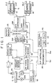
- Fig. 1 is a principle block diagram of an audio data compression-expansion type magneto-optical disc recording and/or reproducing apparatus of the present invention.
- D denotes an optical disc.
- the disc D employed in the present invention is a rewritable optical disc as a magneto-optical disc.
- the magneto-optical disc has a recording layer where data is recordable, reproducible and erasable.
- the disc D has an outer diameter of about 64 mm, and spiral record tracks are formed thereon at a pitch of, e.g., about 1.6 ⁇ m.
- the disc D is rotated at a constant linear velocity (CLV) of, e.g., 1.2 - 1.4 m/sec. Audio data is recorded thereon after being compressed in the form of digital signal, so that data of 130 Mbytes or more can be recorded and reproduced.
- CLV constant linear velocity
- a pregroove or prepits is formed previously for using a tracking control of a light beam emitted from an optical head, later explained. And particularly in the present invention, an absolute address code is recorded in such pregroove in a manner to be superimposed on a tracking-control wobbling signal.
- the disc D is contained in a disc cartridge Crt.
- TOC Table Of Contents
- the mode of each circuit is selectively changed by a mode switching signal R/P obtained from a recording/ playback controller 20 consisting of a microcomputer.
- This controller 20 is controlled by a control signal Sci from a system controller 10 shown in Fig. 4.
- Two-channel analog audio signals received via a pair of input terminals 21LT, 21RT are sampled in an A-D converter 22 at a sampling frequency of 44.1 kHz, and each of the sampled values is converted into a 16-bit digital signal.
- the digital signal thus obtained is then supplied to a data compressor 23R.
- the input digital signal is compressed approximately to 1/5 by the data compressor 23R.
- a variety of data compression methods may be adopted inclusive of 4-bit quantization ADPCM (Adaptive Delta Pulse Code Modulation) and modified DCT (Discrete Cosine Transformation).
- the data thus compressed in the data compressor 23R is transferred to a buffer memory 25 controlled by a memory controller 24.
- the buffer memory 25 consists of a D-RAM having a storage capacity of 1 Mbits.
- the memory controller 24 If there occurs none of track jump which is a phenomenon that the recording position on the disc D jumps due to some vibration or shock during the recording operation, the memory controller 24 reads out the compressed data da sequentially from the buffer memory 25 at a higher transfer rate approximately five times the write rate and then transfers the read data to a data encoder 26.
- the memory controller 24 interrupts the data transfer to the encoder 26R and stores in the buffer memory 25 the compressed data da obtained from the processor 23R. And after correction of the recording position, the memory controller 24 resumes the data transfer from the buffer memory 25 to the encoder 26R.
- Occurrence of a track jump can be detected by providing a vibration indicator or the like in the apparatus and deciding if the indicated vibration is so great or not as to cause a track jump.
- an absolute address code is recorded, at the time of forming a pregroove, in a manner to be superimposed on the wobbling signal as mentioned. Therefore a track jump can be detected also by reading out the absolute address code from the pregroove in the recording mode and judging the continuity of the absolute addresses from the decoded output.
- the circuits may be so modified as to detect a track jump by taking the logic sum of the detection output from the vibration indicator and the absolute address code. It is necessary that, upon occurrence of any track jump, the output power level of the light beam for recording be lowered or switched off.
- Correction of the recording position at the occurrence of a track jump can be executed with reference to the absolute address code of the disc D.
- the buffer memory 25 needs to have at least a storage capacity sufficient for storing the compressed data da which corresponds to the time required from the occurrence of any track jump to the proper correction of the recording position.
- the buffer memory 25 has a storage capacity of 1 Mbits, which is so selected as to ensure an adequate margin for completely satisfying the aforementioned condition.
- the memory controller 24 executes its control action in a manner to minimize the data to be stored in the buffer memory 25. For example, when the amount of the data in the buffer memory 25 has exceeded a predetermined value, merely a fixed amount of the data such as 32 sectors is readout from the buffer memory 25. As a result, the buffer memory 25 is controlled so as to continuously maintain a write space for more than the predetermined amount of data.
- 1 sector is equal to 1 CD-ROM sector of approximately 2 Kbytes.
- the data encoder 26R serves to encode the compressed data da read out from the buffer memory 25 to thereby form data of a CD-ROM sector structure.
- the data including the 32-sector audio data will be referred to as one cluster.
- the output data of a unitary cluster from the data encoder 26R is supplied to a recording encoder 27 which executes a coding process for error detection and correction and also a process of adaptively modulating the data for recording, e.g., EFM (Eight-Fourteen Modulation) in this invention.
- EFM Eight-Fourteen Modulation
- the error detection and correction code is obtained by additionally interleaving and changing the CIRC (Cross Interleave Reed-Solomon code).
- the record data in this case are intermittent ones of unitary clusters
- a splice recording operation is performed for the joints thereof by adding data of several sectors anterior and posterior to the data of each unitary cluster.
- the coded data from the recording encoder 27 is supplied via a drive circuit 28 to a magnetic head 29.
- the magnetic head 29 is driven by the drive circuit 28 to generate a modulated vertical magnetic field according to the recording data and supply the vertical magnetic field to the magneto-optical disc D.
- the record data supplied to the head 29 is in the form of a unitary cluster, and splice recording is performed intermittently.
- the disc D is contained in the disc cartridge Crt.
- a shutter is opened so that the disc D is exposed from an opening formed in the disc cartridge Crt.
- a disc table not shown, provided on a rotary shaft of a disc drive motor 30M is inserted into a spindle hole of the disc cartridge Crt.
- the disc table is engaged with the disc D to thereby rotate the same.
- the disc drive motor 30M is controlled by a servo control circuit, later explained, so as to rotate the disc D at a constant linear velocity (CLV) of 1.2 - 1.4 m/sec.
- the magnetic head 29 is disposed opposite to the disc D which is exposed from the opening of the cartridge Crt.
- An optical head 30 is provided at a position opposite to the reverse side of the disc D with respect to its one side opposite to the magnetic head 29.
- the optical head 30 includes a photodetector, a laser diode as a light beam source, a collimator lens, an objective lens, a polarized beam splitter, and a cylindrical lens.
- a light beam of a fixed power greater than that used in the playback mode is irradiated onto the record track.
- the data is recorded thermomagnetically on the disc D by a combination of the irradiated light beam from the optical head 30 and the modulated vertical magnetic field from the magnetic head 29.
- the magnetic head 29 and the optical head 30 are so arranged as to be movable in the radial direction of the disc D.
- the output of the optical head 30 is supplied via an RF signal processor 31 to an absolute address decoder 34, so that the absolute address code from the pregroove on the disc D is extracted and decoded.
- the absolute address data thus decoded is supplied to the recording encoder 27 to be thereby inserted as absolute address data in the record data and then is recorded on the disc D.
- the absolute address data outputted from the absolute address decoder 34 is supplied also to the recording/ playback controller 20 so as to be used for recognition and control of the recording position on the disc D.
- the output of the RF signal processor 31 is supplied to the servo control circuit 32.
- a control signal is produced on the basis of the signal from the pregroove of the disc D so as to maintain the linear velocity of the motor 30M constant under servo control.
- the disc D loaded in the apparatus is rotated by the disc drive motor 30M. And similarly to the recording mode, the disc drive motor 30M is controlled by the servo control circuit 32 in accordance with the signal obtained from the pregroove. As a result, the rotation of the disc D by the drive motor 30M is maintained constant at the same linear velocity of 1.2 - 1.4 m/sec as in the recording mode.
- the optical head 30 receives the reflected light beam of the light beam irradiated onto a target track, thereby detecting the focus error by astigmatism means or the like. At this time, the tracking error by push-pull means or the like according to the reflected light beam, and further detecting the polarization angle, such as Kerr rotation angle, of the reflected light beam from the target track. Consequently the optical head 30 generates a reproduced RF signal as an output signal .
- the output signal of the optical head 30 is supplied to the RF signal processor 31, which then generates the focus error signal and the tracking error signal from the output signal of the optical head 30.
- the output signal of the optical head 30 further supplies the extracted signals to the servo controller 32 while converting the reproduced signals into binary signals and supplying the same to a playback decoder 33.
- the servo control circuit 32 executes focus control of the optical mechanism for the optical head 30 in a manner to decrease the focus error signal to zero.
- the servo control circuit 32 also executes tracking control of the optical mechanism for the optical head 30 in a manner to decrease the tracking error signal to zero.
- the RF signal processor 31 extracts the absolute address code detecting of the pregroove and supplies the code to an absolute address decoder 34. Then the absolute address data outputted from the decoder 34 is supplied to the recording/playback controller 20 so as to be used by the servo control circuit 32 for position control of the optical head 30 in the radial direction of the disc D. For controlling the position on the record track being scanned by the optical head 30, the recording/playback controller 20 is capable of utilizing also the address data of unitary sectors extracted from the reproduced data.
- the compressed data read from the disc D is written in the buffer memory 25 and then is read out therefrom to be expanded.
- the operation of reading the data from the disc D by the optical head 30 is performed intermittently so that the data stored in the buffer memory 25 is not decreased below a predetermined amount.
- the data read from the disc D is supplied via the RF signal processor 31 to the playback decoder 33.
- the playback decoder 33 executes required processes conforming with those of the recording encoder 27, such as EFM demodulation and interpolation for error detection and correction.
- the output data of the playback decoder 33 is supplied to the data decoder 26P.
- the data decoder 26P decodes the data of the CD-ROM sector structure to resume the former data in the compressed state.
- the output of the data decoder 26P is transferred via the track jump memory controller 24 to the buffer memory 25, where the data is written at a predetermined rate.
- the memory controller 24 If there occurs none of track jump which is a phenomenon that the playback position jumps on the disc due to some vibration or shock during the playback operation, the memory controller 24 reads out the compressed output data of the data decoder 26P sequentially at a lower transfer speed approximately 1/5 times the write speed, and then transfers the read data to the data expander 23P. In this case, the memory controller 24 controls the write and read operation relative to the buffer memory 25 in a manner that the data stored in the buffer memory 25 is maintained below a predetermined amount.
- the memory controller 24 interrupts the action of writing the data from the data decoder 26P into the buffer memory 25 and merely transfers the data to the data expander 23P. And after correction of the playback position on the disc D, the memory controller 24 resumes the action of writing the data from the data decoder 26P into the buffer memory 25.
- Occurrence of a track jump can be detected by various means as in the recording mode; e.g., by providing a vibration indicator or using the output data of the absolute address decoder 34, or by taking the logic sum of the output of a vibration indicator and the absolute address code.
- the buffer memory 25 in the playback mode needs to have at least a storage capacity sufficient for successively storing the data which corresponds to the time required from the occurrence of any track jump to proper correction of the playback position. If such sufficient storage capacity is ensured, proper transfer of the data can be performed continuously from the buffer memory 25 to the data expander 23P despite occurrence of any track jump.
- the storage capacity of 1 Mbits of the buffer memory 25 employed in this invention is so selected as to retain an adequate margin for completely satisfying the above condition.
- the memory controller 24 executes its control action in a manner that a predetermined amount of data greater than the aforementioned minimum necessity is stored in the buffer memory 25. For example, when the data in the buffer memory 25 has been decreased below a predetermined amount, the data from the disc D is intermittently picked up by the optical head 30, and the data obtained from the data decoder 26P is written in the buffer memory 25. As a result, the buffer memory 25 is controlled so as to maintain a sufficient read space greater than the predetermined amount of the data.
- the ADPCM data is expanded approximately 5 times inversely to the process of data compression in the recording mode.
- the digital audio data outputted from the data expander 23P is supplied to a D-A converter 35 to be thereby converted into the former two-channel analog signal, which is then delivered via a pair of output terminals 36LT and 36RT.
- the timing of each operation in the recording section and the playback section above-described is set in accordance with timing signals including the aforementioned sampling frequency signal.
- a timing signal generator 40 has a crystal oscillator 41 and a frequency divider 42 employing a phase-locked loop (PLL).
- PLL phase-locked loop
- the clock frequencies used in the individual circuits are set as follows. Recording/playback controller 20 12 MHz Data compressor 23R 55 MHz Data expander 23P 55 MHz Recording encoder 27 22.6 MHz Playback decoder 33 22.6 MHz
- the frequency of the recording current supplied to the magnetic head 29 is set to 800 kHz or so.
- the recording/playback unit above-mentioned is housed together with a radio receiving unit in a single cabinet.
- An input signal received by the radio receiving unit is recordable on a recording medium by the recording/playback unit.
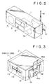
- the above-mentioned magneto-optical disc recording/playback unit 2 is disposed at a lower center position of a cabinet 1 composed of synthetic resin.
- An LCD (Liquid Crystal Display) device 3 for displaying the operating state and so forth of the recording/playback unit 2 is disposed thereabove.
- An AM-FM broadcast tuner 4 is disposed in a rear right area of the cabinet 1. Both an AM bar antenna 4a and an FM rod antenna 4f are connected to the tuner 4. Further loudspeakers 7L, 7R are disposed at left and right ends of the cabinet 1 respectively.
- the output audio signal of the tuner 4 is supplied via a selector 5 and a power amplifier 6 to the loudspeakers 7L and 7R. Meanwhile the power from a battery 8 is supplied via a power switch 9 to individual component circuits.
- Denoted by 10 is a system controller consisting of a microcomputer to which a plurality of keys Ka - Kn are connected. Various control actions are executed by manipulating such keys to set the operation mode and so forth for the disc recording/playback unit 2 and the tuner 4.
- the selector 5 is so connected as to distribute the output audio signal of the tuner 4 as an input audio signal Sr to the recording/playback unit 2 or to supply the output audio signal Sp of the recording/playback unit 2 to the power amplifier 6.
- the power amplifier 6 and the microcomputer 10 are disposed in, e.g., an upper centre area of the cabinet 1.
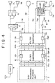
- Fig. 3 illustrates a disc recording/playback unit 2 housed in a case 11 of a tin-plated steel sheet and shielded electromagnetically.
- a cover 11c of a shielding material is provided on a slot 11s formed in the case 11 for insertion of a disc or a disc cartridge.
- filter boards 12 and 13 are disposed inside and outside the shield case 11 respectively.
- Each of the filter boards 12 and 13 is composed of, e.g., a laminated plate with copper sheets stuck to both surfaces thereof, and a wiring pattern is formed on one surface. Required component elements are soldered to such one surface, while the other surface is used as a grounding conductor.
- the two filter boards 12 and 13 are attached to the case 11 in a state where the wiring pattern surface is sandwiched between the grounding conductor surface and the wall of the case 11.
- the filter boards 12 and 13 are connected to each other by means of a lead assembly 14th which includes a plurality of wires led out through the case 11.
- the outer filter board 13 is connected to the circuits outside the case 11 by means of a lead assembly 14os.
- the lead assemblies 14th and 14os employed in this embodiment are composed of shielded wires.
- a plurality of elemental wires are grouped to form a flat bundle, and the ends thereof are connected to a flat connector CN.
- a capacitor, not shown, of an adequate capacitance may be additionally provided at the position of the shield case 11 where the lead assembly 14th pierces.
- low-pass filters 12a -12n and 13a - 13n are mounted on the filter boards 12 and 13 respectively so as to attenuate the unrequited high-frequency components radiated from the recording/playback unit 2.
- Ground ends 12gd, 13gd of the filter boards 12, 13 are connected respectively to the shield case 11 which is grounded at proper positions thereof.
- the case 11 is grounded at one or more internal positions while being also grounded at one or more external positions.
- the ground positions of the case 11 may be common on the two filter boards 12 and 13.
- the entire inputs and outputs of the disc recording/playback unit 2 in the shield case 11 are transferred via the two filter boards 12 and 13 to and from the circuits outside the case 11.
- the exemplary inputs and outputs of the disc recording/playback unit 2 are as follows.
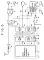
- the disc recording/playback unit 2 has a circuit to generate high-frequency clock pulses for the high-frequency recording current and the digital process. And unrequited high-frequency components derived from such high-frequency currents, clock pulses and higher and lower harmonics thereof are radiated from the recording/playback unit 2 and enter into the AM-FM tuner 4 disposed in the proximity of the unit 2 as shown in Fig. 2. As a result, satisfactory reception of a radio broadcast is disturbed.
- the disc recording/playback unit 2 is housed in the shield case 11 for the purpose of suppressing the radiation of such unrequited high-frequency components.
- the filter board 12 is provided in the case 11, and low-pass filters 12a - 12n mounted on the board 12 serve to attenuate the unrequited high-frequency components which are radiated from the circuits of the recording/playback unit 2 and are superimposed on the lead assembly 14os in the case 11.
- the second filter substrate 13 is provided outside the case 11, and the unrequited high-frequency components remaining on the lead assembly 14th are attenuated by low-pass filters 13a - 13n mounted on the board 13.
- the level of the unrequited high-frequency components can be lowered on the lead assembly 14os disposed on the output side of the filter board 13, whereby the high-frequency noise entering into the tuner 4 is reduced to a remarkable extent to consequently ensure satisfactory reception of a radio broadcast.
- a disc recording/playback unit 2 is housed in a shield case 11, and further opto-electric conversion blocks 15, 16 are also contained in the shield case 11. Electro-optical conversion blocks 17, 18 corresponding respectively to the input and output signals of the recording/playback unit 2 are disposed outside the shield case 11 respectively.
- Each of the opto-electric conversion blocks 15, 17 consists of an opto-electric conversion element such as a photodiode
- each of the electro-optical conversion blocks 16, 18 consists of an electro-optical conversion element such as a light emitting diode.
- the opto-electrical conversion blocks 16, 17 and the electro-optical conversion blocks 15, 18 are connected to each other by means of an optical fiber 19, so that the aforementioned input and output signals are transferred in the form of optical signals between the circuits outside the shield case 11 and the disc recording/playback unit 2 housed in the case 11. Since the power for the recording/playback unit 2 is supplied through a lead assembly 14, a filter such as the aforesaid one may be inserted when necessary.
- the input and output signals of the disc recording/playback unit 2 are transferred via the optical signal path to and from the tuner 4 and the other circuits, so that the noise derived from the electromagnetic waves leaking from the recording/playback unit 2 in the shield case 11 is diminished to consequently cause remarkable reduction of the high-frequency noise entering into the tuner 4, whereby a radio broadcast is rendered receivable in a satisfactory state.
Landscapes
- Engineering & Computer Science (AREA)
- Multimedia (AREA)
- Signal Processing For Digital Recording And Reproducing (AREA)
- Shielding Devices Or Components To Electric Or Magnetic Fields (AREA)
- Structure Of Receivers (AREA)
- Noise Elimination (AREA)
- Input Circuits Of Receivers And Coupling Of Receivers And Audio Equipment (AREA)
Claims (7)
- In einem Gehäuse befindliches Aufzeichnungs- und/oder Wiedergabegerät mit Rundfunk-Empfangsfunktion aufweisendeine Rundfunk-Empfangseinheit (4) undeine Aufzeichnungs-/Wiedergabeeinheit (2) dadurch gekennzeichnet,daß die Aufzeichnungs-/Wiedergabeeinheit (2) einen Hochfrequenz-Taktgeber (40) aufweist und, im Betrieb, Hochfrequenz-Aufzeichnungsströme erzeugt und ferner aufweistein Abschirmgehäuse (11), um die Aufzeichnungs-/Wiedergabeeinheit (2) von elektromagnetischen Wellen einschließlich Hochfrequenz-Aufzeichnungsströmen und deren Harmonischem gänzlich abzuschirmen, undMittel, um die Ausbreitung von Hochfrequenz-Signalen einschließlich der Hochfrequenz-Aufzeichnungsströme und deren Harmonischen zumindest in Richtung vom Inneren zum Äußeren des Abschirmgehäuses zu unterdrücken, wobei diese Mittel zur Unterdrückung aufweisenein erstes elektro-optisches Umsetzungsteil (15,16) im Inneren des Abschirmgehäuses (11), um ein elektrisches Ausgangssignal der Aufzeichnungs-/Wiedergabeeinheit in ein optisches Ausgangssignal umzusetzen und auch um ein optisches Eingangssignal der Aufzeichnungs-/Wiedergabeeinheit in ein elektrisches Eingangssignal umzusetzen; undein zweites elektro-optisches Umsetzungsteil (17,18) außerhalb des Abschirmgehäuses (11), um das optische Ausgangssignal in ein elektrisches Ausgangssignal und auch ein elektrisches Eingangssignal in das optische Eingangssignal umzusetzen.
- Gerät gemäß Anspruch 1,
in welchem die Aufzeichnungs-/Wiedergabeeinheit (2) einen Magnetkopf (29), ein Eingabeteil (21), ein Signalverarbeitungsteil (22-27), um eine vorbestimmte Verarbeitung des von dem Eingabeteil erhaltenen Eingangssignals auszuführen, ein Modulationsteil (28), um eine vorbestimmte Modulation des Ausgangssignals des Signalverarbeitungsteil (22-27) auszuführen, ein Ansteuerteil (28), um den Magnetkopf unter Verwendung des von dem Modulationsteil erhaltenen modulierten Signals anzusteuern, und ein Steuerteil (20) aufweist, um die Aufzeichnungs-/Wiedergabeeinheit (2) zu steuern. - Gerät gemäß Anspruch 2,
in welchem die Aufzeichnungs-/Wiedergabeeinheit (2) ferner einen optischen Kopf (30) aufweist, der gegenüber dem magnetischen Kopf (29) angeordnet ist. - Gerät gemäß Anspruch 2 oder 3,
in welchem der Hochfrequenz-Taktgeber (40) wenigstens eines von Steuerteil, Modulationsteil, Magnetkopf und Signalverarbeitungsteil ist. - Gerät gemäß Anspruch 2,3 oder 4,
in welchem das von dem Eingabeteil (21) erhaltene Eingangssignal das von der Rundfunk-Empfangseinheit empfangene Signal ist. - Gerät nach einem der vorhergehenden Ansprüche,
in welchem das der Aufzeichnungs-/Wiedergabeeinheit zugeführte Eingangssignal das von der Rundfunk-Empfangseinheit empfangene Signal ist. - Gerät nach einem der vorhergehenden Ansprüche das
zur Aufzeichnung/Wiedergabe von Platten (discs) ausgebildet ist.
Applications Claiming Priority (4)
| Application Number | Priority Date | Filing Date | Title |
|---|---|---|---|
| JP351681/92 | 1992-12-08 | ||
| JP35168192 | 1992-12-08 | ||
| JP04351681A JP3104773B2 (ja) | 1992-12-08 | 1992-12-08 | 無線受信機能付き記録再生装置 |
| EP93309870A EP0601841B1 (de) | 1992-12-08 | 1993-12-08 | Vorrichtung zur Reduzierung von elektromagnetischer Interferenz in einem Aufzeichnungs- und/oder Wiedergabegerät mit Rundfunk-Empfangs-Funktion |
Related Parent Applications (2)
| Application Number | Title | Priority Date | Filing Date |
|---|---|---|---|
| EP93309870.9 Division | 1993-12-08 | ||
| EP93309870A Division EP0601841B1 (de) | 1992-12-08 | 1993-12-08 | Vorrichtung zur Reduzierung von elektromagnetischer Interferenz in einem Aufzeichnungs- und/oder Wiedergabegerät mit Rundfunk-Empfangs-Funktion |
Publications (3)
| Publication Number | Publication Date |
|---|---|
| EP0829878A2 EP0829878A2 (de) | 1998-03-18 |
| EP0829878A3 EP0829878A3 (de) | 1998-08-12 |
| EP0829878B1 true EP0829878B1 (de) | 2001-05-23 |
Family
ID=18418903
Family Applications (2)
| Application Number | Title | Priority Date | Filing Date |
|---|---|---|---|
| EP93309870A Expired - Lifetime EP0601841B1 (de) | 1992-12-08 | 1993-12-08 | Vorrichtung zur Reduzierung von elektromagnetischer Interferenz in einem Aufzeichnungs- und/oder Wiedergabegerät mit Rundfunk-Empfangs-Funktion |
| EP97119783A Expired - Lifetime EP0829878B1 (de) | 1992-12-08 | 1993-12-08 | Vorrichtung zur Reduzierung von elektromagnetischer Interferenz in einem Aufzeichnungs- und/oder Wiedergabegerät mit Rundfunkempfangsfunktion |
Family Applications Before (1)
| Application Number | Title | Priority Date | Filing Date |
|---|---|---|---|
| EP93309870A Expired - Lifetime EP0601841B1 (de) | 1992-12-08 | 1993-12-08 | Vorrichtung zur Reduzierung von elektromagnetischer Interferenz in einem Aufzeichnungs- und/oder Wiedergabegerät mit Rundfunk-Empfangs-Funktion |
Country Status (5)
| Country | Link |
|---|---|
| US (1) | US5446707A (de) |
| EP (2) | EP0601841B1 (de) |
| JP (1) | JP3104773B2 (de) |
| KR (1) | KR100295563B1 (de) |
| DE (2) | DE69321692T2 (de) |
Cited By (1)
| Publication number | Priority date | Publication date | Assignee | Title |
|---|---|---|---|---|
| TWI447721B (zh) * | 2009-01-09 | 2014-08-01 | Ibm | 在偵測一錯誤之情況下重寫碼字物件至磁性資料帶之方法及資料帶驅動機及電腦程式產品 |
Families Citing this family (7)
| Publication number | Priority date | Publication date | Assignee | Title |
|---|---|---|---|---|
| JPH0836833A (ja) * | 1994-07-22 | 1996-02-06 | Matsushita Electric Ind Co Ltd | ディスクの情報読み出し制御装置および読み出し制御方法 |
| US5920539A (en) * | 1995-01-25 | 1999-07-06 | Discovision Associates | Apparatus and method for suppression of electromagnetic emissions having a groove on an external surface for passing an electrical conductor |
| US5845195A (en) * | 1996-07-17 | 1998-12-01 | Miodownik; Saul | Digital radio frequency communications device for insertion into floppy diskette drive |
| KR100546270B1 (ko) * | 1998-03-09 | 2006-03-23 | 삼성전자주식회사 | 무선방식의 하드디스크 드라이브 및 그 데이터 전송방법 |
| JPH11289169A (ja) * | 1998-04-03 | 1999-10-19 | Nec Shizuoka Ltd | 電子機器の情報表示窓 |
| RU2148862C1 (ru) * | 1999-09-20 | 2000-05-10 | Ровнер Яков Шоел-Берович | Мобильная система караоке, способ обеспечения электромагнитной совместимости для мобильной системы караоке, мобильное беспроводное передающее устройство для нее, картридж для нее, способ предотвращения использования неавторизованных картриджей в ней и способ для предотвращения несанкционированного доступа к данным в ней |
| US20090260560A1 (en) * | 2008-04-21 | 2009-10-22 | Rave Sports Inc. | Watercraft including a floatable slide and a boat |
Citations (1)
| Publication number | Priority date | Publication date | Assignee | Title |
|---|---|---|---|---|
| DE4030782A1 (de) * | 1990-09-28 | 1992-04-02 | Siemens Ag | Optische schnittstelle |
Family Cites Families (7)
| Publication number | Priority date | Publication date | Assignee | Title |
|---|---|---|---|---|
| JPS55141841A (en) * | 1979-04-23 | 1980-11-06 | Nissan Motor Co Ltd | Noise suppression unit |
| JPS5880946A (ja) * | 1981-11-06 | 1983-05-16 | Nintendo Co Ltd | 信号伝送システム |
| JPS58173927A (ja) * | 1982-04-06 | 1983-10-12 | Nissan Motor Co Ltd | 車載電子機器の電源ノイズ除去装置 |
| NL8600288A (nl) * | 1986-02-06 | 1987-09-01 | Nederlanden Staat | Inrichting voor het vormen van een van electromagnetische stralingsoverdracht bevrijde galvanische verbinding tussen geleiders. |
| JP3122102B2 (ja) * | 1989-09-13 | 2001-01-09 | ソニー株式会社 | 受信機 |
| JP2995822B2 (ja) * | 1990-08-23 | 1999-12-27 | ソニー株式会社 | 円盤状記録媒体の記録装置及び再生装置 |
| US5165055A (en) * | 1991-06-28 | 1992-11-17 | Digital Equipment Corporation | Method and apparatus for a PCB and I/O integrated electromagnetic containment |
-
1992
- 1992-12-08 JP JP04351681A patent/JP3104773B2/ja not_active Expired - Fee Related
-
1993
- 1993-11-23 US US08/156,457 patent/US5446707A/en not_active Expired - Fee Related
- 1993-12-07 KR KR1019930026677A patent/KR100295563B1/ko not_active IP Right Cessation
- 1993-12-08 EP EP93309870A patent/EP0601841B1/de not_active Expired - Lifetime
- 1993-12-08 DE DE69321692T patent/DE69321692T2/de not_active Expired - Fee Related
- 1993-12-08 EP EP97119783A patent/EP0829878B1/de not_active Expired - Lifetime
- 1993-12-08 DE DE69330258T patent/DE69330258T2/de not_active Expired - Fee Related
Patent Citations (1)
| Publication number | Priority date | Publication date | Assignee | Title |
|---|---|---|---|---|
| DE4030782A1 (de) * | 1990-09-28 | 1992-04-02 | Siemens Ag | Optische schnittstelle |
Cited By (1)
| Publication number | Priority date | Publication date | Assignee | Title |
|---|---|---|---|---|
| TWI447721B (zh) * | 2009-01-09 | 2014-08-01 | Ibm | 在偵測一錯誤之情況下重寫碼字物件至磁性資料帶之方法及資料帶驅動機及電腦程式產品 |
Also Published As
| Publication number | Publication date |
|---|---|
| JP3104773B2 (ja) | 2000-10-30 |
| DE69321692T2 (de) | 1999-04-15 |
| DE69330258D1 (de) | 2001-06-28 |
| KR940016215A (ko) | 1994-07-22 |
| DE69330258T2 (de) | 2001-11-08 |
| KR100295563B1 (ko) | 2001-09-17 |
| EP0829878A3 (de) | 1998-08-12 |
| EP0601841A2 (de) | 1994-06-15 |
| JPH06177574A (ja) | 1994-06-24 |
| DE69321692D1 (de) | 1998-11-26 |
| US5446707A (en) | 1995-08-29 |
| EP0601841A3 (de) | 1994-08-03 |
| EP0601841B1 (de) | 1998-10-21 |
| EP0829878A2 (de) | 1998-03-18 |
Similar Documents
| Publication | Publication Date | Title |
|---|---|---|
| KR930009536B1 (ko) | 기록 재생 장치 | |
| KR100213416B1 (ko) | 디스크 기록/재생 장치 | |
| US5502701A (en) | Optical disc recording apparatus which controls re-recording after a disturbance as a function of the capacity of an input buffer memory | |
| RU2105356C1 (ru) | Устройство для воспроизведения информации с дискового носителя записи | |
| EP0700039B1 (de) | Optisches Aufzeichnungs-/Wiedergabegerät | |
| CA2034599A1 (en) | Recording and reproducing apparatus | |
| EP0829878B1 (de) | Vorrichtung zur Reduzierung von elektromagnetischer Interferenz in einem Aufzeichnungs- und/oder Wiedergabegerät mit Rundfunkempfangsfunktion | |
| EP0926904B1 (de) | Aufnahmegerät und Aufnahmeverfahren | |
| EP0139332B1 (de) | Gerät zur Wiedergabe von Informationen auf einem plattenförmigen, optisch lesbaren Informationsträger | |
| EP0571221B1 (de) | Plattenaufzeichnungsgerät und Plattenaufzeichnungsverfahren | |
| US4613967A (en) | Disc player | |
| CA1312140C (en) | Fast speed reproduction system for digital disc | |
| GB2099202A (en) | Rotary recording medium and reproducing apparatus therefor | |
| US5703854A (en) | Disc recording/reproduction apparatus and method for resetting an address control circuit to maximize an address margin of the memory | |
| KR100306173B1 (ko) | 디스크수납광체 | |
| EP0762393B1 (de) | Erzeugung von Spurenzählimpulsen | |
| JPH10335868A (ja) | 放送受信機能付き記録再生装置 | |
| JP2822585B2 (ja) | ディスク記録装置及びディスク再生装置 | |
| JPH08124279A (ja) | ディスク状記録媒体の記録及び/又は再生装置 | |
| JPH04105270A (ja) | ディスク記録装置及びディスク再生装置 | |
| JP2612693B2 (ja) | デイスク再生装置におけるビデオ信号処理装置 | |
| KR19980020368A (ko) | 디스크 재생방법 | |
| JPH08124277A (ja) | 光磁気ディスクの記録装置 | |
| JPH0410229A (ja) | 光学式ディスク再生装置 | |
| JPS6177157A (ja) | 磁気記録再生装置の頭出し記録方式 |
Legal Events
| Date | Code | Title | Description |
|---|---|---|---|
| PUAI | Public reference made under article 153(3) epc to a published international application that has entered the european phase |
Free format text: ORIGINAL CODE: 0009012 |
|
| AC | Divisional application: reference to earlier application |
Ref document number: 601841 Country of ref document: EP |
|
| AK | Designated contracting states |
Kind code of ref document: A2 Designated state(s): DE FR GB |
|
| PUAL | Search report despatched |
Free format text: ORIGINAL CODE: 0009013 |
|
| AK | Designated contracting states |
Kind code of ref document: A3 Designated state(s): DE FR GB |
|
| 17P | Request for examination filed |
Effective date: 19990120 |
|
| 17Q | First examination report despatched |
Effective date: 19990407 |
|
| GRAG | Despatch of communication of intention to grant |
Free format text: ORIGINAL CODE: EPIDOS AGRA |
|
| GRAG | Despatch of communication of intention to grant |
Free format text: ORIGINAL CODE: EPIDOS AGRA |
|
| GRAG | Despatch of communication of intention to grant |
Free format text: ORIGINAL CODE: EPIDOS AGRA |
|
| GRAH | Despatch of communication of intention to grant a patent |
Free format text: ORIGINAL CODE: EPIDOS IGRA |
|
| GRAH | Despatch of communication of intention to grant a patent |
Free format text: ORIGINAL CODE: EPIDOS IGRA |
|
| GRAA | (expected) grant |
Free format text: ORIGINAL CODE: 0009210 |
|
| AC | Divisional application: reference to earlier application |
Ref document number: 601841 Country of ref document: EP |
|
| AK | Designated contracting states |
Kind code of ref document: B1 Designated state(s): DE FR GB |
|
| REF | Corresponds to: |
Ref document number: 69330258 Country of ref document: DE Date of ref document: 20010628 |
|
| ET | Fr: translation filed | ||
| PGFP | Annual fee paid to national office [announced via postgrant information from national office to epo] |
Ref country code: GB Payment date: 20011212 Year of fee payment: 9 Ref country code: FR Payment date: 20011212 Year of fee payment: 9 |
|
| REG | Reference to a national code |
Ref country code: GB Ref legal event code: IF02 |
|
| PGFP | Annual fee paid to national office [announced via postgrant information from national office to epo] |
Ref country code: DE Payment date: 20020109 Year of fee payment: 9 |
|
| PLBE | No opposition filed within time limit |
Free format text: ORIGINAL CODE: 0009261 |
|
| STAA | Information on the status of an ep patent application or granted ep patent |
Free format text: STATUS: NO OPPOSITION FILED WITHIN TIME LIMIT |
|
| 26N | No opposition filed | ||
| PG25 | Lapsed in a contracting state [announced via postgrant information from national office to epo] |
Ref country code: GB Free format text: LAPSE BECAUSE OF NON-PAYMENT OF DUE FEES Effective date: 20021208 |
|
| PG25 | Lapsed in a contracting state [announced via postgrant information from national office to epo] |
Ref country code: DE Free format text: LAPSE BECAUSE OF NON-PAYMENT OF DUE FEES Effective date: 20030701 |
|
| GBPC | Gb: european patent ceased through non-payment of renewal fee | ||
| PG25 | Lapsed in a contracting state [announced via postgrant information from national office to epo] |
Ref country code: FR Free format text: LAPSE BECAUSE OF NON-PAYMENT OF DUE FEES Effective date: 20030901 |
|
| REG | Reference to a national code |
Ref country code: FR Ref legal event code: ST |