EP0826818A2 - Procédé et dispositif pour régler le profil de la consistance et de l'orientation des fibres dans une caisse de tête - Google Patents
Procédé et dispositif pour régler le profil de la consistance et de l'orientation des fibres dans une caisse de tête Download PDFInfo
- Publication number
- EP0826818A2 EP0826818A2 EP97111794A EP97111794A EP0826818A2 EP 0826818 A2 EP0826818 A2 EP 0826818A2 EP 97111794 A EP97111794 A EP 97111794A EP 97111794 A EP97111794 A EP 97111794A EP 0826818 A2 EP0826818 A2 EP 0826818A2
- Authority
- EP
- European Patent Office
- Prior art keywords
- flow
- turbulence
- suspension
- headbox
- angle
- Prior art date
- Legal status (The legal status is an assumption and is not a legal conclusion. Google has not performed a legal analysis and makes no representation as to the accuracy of the status listed.)
- Withdrawn
Links
Images


Classifications
-
- D—TEXTILES; PAPER
- D21—PAPER-MAKING; PRODUCTION OF CELLULOSE
- D21F—PAPER-MAKING MACHINES; METHODS OF PRODUCING PAPER THEREON
- D21F1/00—Wet end of machines for making continuous webs of paper
- D21F1/02—Head boxes of Fourdrinier machines
- D21F1/022—Means for injecting material into flow within the headbox
-
- D—TEXTILES; PAPER
- D21—PAPER-MAKING; PRODUCTION OF CELLULOSE
- D21F—PAPER-MAKING MACHINES; METHODS OF PRODUCING PAPER THEREON
- D21F1/00—Wet end of machines for making continuous webs of paper
- D21F1/02—Head boxes of Fourdrinier machines
-
- D—TEXTILES; PAPER
- D21—PAPER-MAKING; PRODUCTION OF CELLULOSE
- D21F—PAPER-MAKING MACHINES; METHODS OF PRODUCING PAPER THEREON
- D21F1/00—Wet end of machines for making continuous webs of paper
- D21F1/02—Head boxes of Fourdrinier machines
- D21F1/026—Details of the turbulence section
-
- D—TEXTILES; PAPER
- D21—PAPER-MAKING; PRODUCTION OF CELLULOSE
- D21F—PAPER-MAKING MACHINES; METHODS OF PRODUCING PAPER THEREON
- D21F1/00—Wet end of machines for making continuous webs of paper
- D21F1/08—Regulating consistency
Definitions
- the invention relates to a headbox for a paper machine according to the Preamble of claim 1 and a method for adjusting the Material density and fiber orientation cross profile in a headbox according to the preamble of claim 10.
- Material density-controlled headboxes for adjusting the material density and Fiber orientation cross profiles are from a variety of applications known.
- the water or can also be a diluted stock suspension are parallel to these feed lines for a diluent, the water or can also be a diluted stock suspension.
- the dilution takes place in that the control current through the slow suspension stream flowing in the distribution pipe along the machine width Is deflected 180 ° and so with the input side into the distribution pipe fed in the suspension stream in the respective area of the Turbulence insert entering suspension stream forms with respect to Material density compared to that fed into the distribution pipe Corresponding suspension flow while keeping the volume flow constant was discontinued.
- a disadvantage of headboxes according to the first concept is that due to the only very small diameter of the dilution tubes Exit rate of the diluent or control flows into the Distribution pipe is very high. This requires a relatively large broad impact such control current, which has the consequence that the consistency in the individual sections of the headbox can only be set very roughly can. Furthermore, such thin tubes only allow the implementation of very small doses, so the range in which the consistency relative to the specified average consistency of the in the distribution pipe entering suspension flow can be set is very low.
- the suspension flow is fed again via a common distribution pipe, sectioned, that is in partial streams that are independent of one another across the width of the headbox, so-called section streams. This can be done, for example happen that the headbox across its width through partitions is divided into sections.
- the consistency is then adjusted by adding Control currents in the individual sections in a mixer.
- the one assigned to the individual sections closes Turbulence insert on.
- the consistency of the respective section streams is set, the Volume flow of the section flow is kept constant.
- DE 43 23 263 is for a sectioned headbox according to the DE 40 19 593 made known that the control current at angles between 5 ° and 90 ° in relation to the main flow direction in the individual sections can be injected.
- a disadvantage of the headboxes according to the second concept is that the Always set a material density and fiber orientation cross profile assumes that the supplied suspension stream is divided into partial streams is going to be in a subsequent mixer for the individual Sections to be adjusted accordingly.
- the object of the invention is therefore to offer a headbox in which the disadvantages of the arrangements according to the prior art avoided will.
- a headbox is to be created in which without a sectioning of the suspension stream introduced into the headbox is sufficient sharp regulation of the material density cross profile is made possible. Especially the width effect compared to that known from US 5196091 Device improved, that is, minimized.
- the invention is also intended to provide a method with which a Adjustment of the fabric density and basis weight cross profile is possible, whereby a division of the partial streams is avoided and still one sufficiently low broad impact is observed.
- this object is achieved by the headbox in claim 1 and the method according to claim 10 is achieved.
- the plurality of supply lines for the Control currents as in US 5196091 directly into the machine-wide distribution pipe flow out.
- the supply lines are immediately before the upstream end arranged of the turbulence insert, the suspension flow in this Only one flow component in the direction of the Has turbulence insert.
- As an angle, under which the supply line for the control current is introduced into the distribution pipe are angles between 5 ° and 170 ° with respect to the flow direction of the Suspension flow possible in turbulence, but is preferred under injected at a right angle.
- control currents directly before the suspension stream enters the Turbulence insert are preferably fed at a right angle. It is particularly preferred if the control current speed is selected in this way will be the most distant from the feed opening Turbulence tube of the turbulence insert a flow component in Direction of the injection and transverse to the direction of the suspension flow is present.
- Fig. 1 is a longitudinal section through a headbox according to the invention shown.
- the stock suspension is fed over a distribution pipe 1 along the machine width made available.
- the distributor pipe has one on the inflow side larger diameter 3 than 5 on the outlet side.
- the distribution pipe 1 is direct connected to the turbulence insert 7.
- the supply lines 13 for the control currents so-called Control power supply lines, provided.
- control valves 15 To the control current, which over the Lines 13 of the suspension stream flowing into the turbulence insert control valves 15 are in the supply line provided by an appropriate control or regulation, such as from DE 42 39 845, the disclosure content of which is fully in the application is involved, can be controlled known.
- Such Regulation is not shown in the present exemplary embodiment.
- Turbulence insert 7 comprises a plurality of in one embodiment Turbulence tubes 20, one over the height h of the turbulence insert
- a plurality of turbulence tubes 201, 202, 203, 204, 205 in a column 200 can be arranged.
- adjustable Apertures 32, 34 are provided, from which the material jet through a Outlet opening 36 flows out.
- Fig. 2 is an enlarged view again the input side Area of the headbox according to the invention shown in FIG. 1 with the there prevailing flow conditions shown in section.
- the Distribution tube 1 is the suspension from the paper plane of the drawing like represented by arrow 40 in the direction of the machine width.
- the distribution pipe itself finds a deflection according to the suspension flow Arrow 40 in the machine longitudinal direction, that is, on the input side End 11 of the turbulence insert 7, instead. It results in the connection area of the distribution pipe 9 a flow behavior as shown by arrow 42, i.e. in the direction of the turbulence insert.
- a control current 50 is fed into the connection area 9 via the feed line 13 the distribution pipe at an angle ⁇ , which in the present case is 90 °, fed.
- the control current 50 has a sufficiently high speed on, so that also at the feed opening 52 opposite end of the Distribution tube, that is, at a distance h from the feed opening, the Control current is a component perpendicular to the direction of the Has suspension flow 42. But serves to adjust the consistency only that existing at the inflow end 11 of the turbulence insert Component of the control current parallel to the direction of the Suspension flow 42. That means the control current must be used to adjust the Fabric density can be redirected.
- a deflection ⁇ 180 ° of the flow direction has a number of advantages over the injection according to US 5196091.
- the size of the feed opening can be chosen arbitrarily and is not limited by that of the surrounding turbulence tube as in the above-mentioned US patent.
- a larger feed opening allows the control streams to be injected at a lower speed and with a higher consistency, so that a greater range of variation ⁇ ⁇ 0 for the adjustability of the consistency increases by an average, supplied consistency value ⁇ 0 .
- This allows the stock density to be at least in one area across the width of the headbox ⁇ 0 - ⁇ 0 ⁇ ⁇ (d) ⁇ ⁇ 0 + ⁇ can be adjusted.
- Another advantage is that due to the low Injection speed and a deflection of the control current, the smaller than 180 °, the width effect of the injected control current is less than in the case of the above-mentioned US 5196091. This in turn has the advantage that the fabric density in the desired area is relatively sharply limited exactly can be set without overlapping the control effect comes in neighboring areas that are very difficult to influence can.
- FIG. 3 shows a top view of a headbox according to FIG. 1, however only part of the total machine width b is shown.
- the distribution pipe 1 which extends over the entire machine width b, tapering from the inflow to the outflow end formed, that is, the cross section 3 at The inlet end is larger than the cross section 5 at the outlet end 60.
- an outlet nozzle 62 through the outlet end through which the portion of the suspension stream supplied, which is not as indicated by arrow 40 in Direction of the turbulence insert is deflected, can be dissipated.
- the turbulence insert 7 comprises adjacent tube bundles, that is, arranged in a row or pipe gaps of turbulence pipes 20. In the present Embodiments are a total of five in the sectional view adjacent turbulence pipes 2000, 2001, 2002, 2003 and 2004 shown. At the turbulence insert 7 one closes on the Machine width adjustable aperture 32 on.
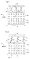
- Fig. 4 is the input end 11 of the turbulence insert, the a perforated plate 100 is closed off from the distribution pipe, shown.
- the perforated plate 100 has arranged in columns and rows Openings 110 for the adjoining turbulence tubes 20, in the present example, these in a column with six superposed turbulence pipes next to each other in series over the entire machine width b are arranged.
- are the feed openings 52 with the adjoining ones Supply lines 13 for the control currents at the upper end of not here shown distribution pipe, with which the plate 100 closes, attached.
- Each supply line 13 is assigned a control valve 15, which in turn is on a common control power supply line 112 through which the Diluent, for example the diluted suspension or also regulated only in the corresponding areas of the water Distribution tube can be supplied.
- 5 are the standard supply lines at an angle ⁇ ⁇ 90 ° to the Horizontal in a plane parallel to the plane of the entry surface of the Stock suspension arranged in the turbulence bundle.
- control currents 50 By injecting the control currents 50 at an angle ⁇ ⁇ 90 ° the control currents a component opposite to the direction of the Suspension stream 40 on. This can deflect the control currents reduced by the suspension flow or completely if ⁇ is correctly selected be avoided. Ideally, there is a broad effect 402 of the Control current, which is limited to a pipe gap.
- To prefer means on the feed lines 13 with which the inclination the same and thus ⁇ can be changed or adjusted.
- the deflection of the flow direction of the Control current is ⁇ 180 °.
Landscapes
- Paper (AREA)
Applications Claiming Priority (2)
| Application Number | Priority Date | Filing Date | Title |
|---|---|---|---|
| DE19634993 | 1996-08-30 | ||
| DE19634993A DE19634993A1 (de) | 1996-08-30 | 1996-08-30 | Verfahren und Vorrichtung zum Einstellen des Stoffdichte- und Faserorientierungsprofils in einem Stoffauflauf |
Publications (2)
| Publication Number | Publication Date |
|---|---|
| EP0826818A2 true EP0826818A2 (fr) | 1998-03-04 |
| EP0826818A3 EP0826818A3 (fr) | 1998-04-01 |
Family
ID=7804064
Family Applications (1)
| Application Number | Title | Priority Date | Filing Date |
|---|---|---|---|
| EP97111794A Withdrawn EP0826818A3 (fr) | 1996-08-30 | 1997-07-11 | Procédé et dispositif pour régler le profil de la consistance et de l'orientation des fibres dans une caisse de tête |
Country Status (4)
| Country | Link |
|---|---|
| US (1) | US6136152A (fr) |
| EP (1) | EP0826818A3 (fr) |
| CN (1) | CN1175644A (fr) |
| DE (1) | DE19634993A1 (fr) |
Families Citing this family (6)
| Publication number | Priority date | Publication date | Assignee | Title |
|---|---|---|---|---|
| DE19908898A1 (de) * | 1999-03-02 | 2000-09-07 | Voith Sulzer Papiertech Patent | Verfahren zur Zudosierung eines fluiden Mediums in einen Suspensionsstrom eines Stoffauflaufes und Stoffauflauf |
| FI105407B (fi) * | 1999-05-27 | 2000-08-15 | Valmet Corp | Paperikoneen tai kartonkikoneen perälaatikko |
| US6902650B2 (en) * | 2002-11-01 | 2005-06-07 | International Paper Company | Method of making a stratified paper |
| HUP0700557A2 (en) * | 2005-02-03 | 2008-02-28 | Pmt Intalia S P A | Apparatus and method for controlling the consistency of a flow of atock solution in a papermaking machine |
| CN102154914B (zh) * | 2011-02-24 | 2013-03-20 | 钟洲 | 制备芳纶纸的方法及由该方法获得的芳纶纸 |
| EP3088604B1 (fr) * | 2015-04-28 | 2020-03-25 | Valmet Technologies Oy | Procédé et système pour l`optimisation des propriétés d'une bande de fibres multicouche pendant la fabrication de bandes de fibres |
Citations (3)
| Publication number | Priority date | Publication date | Assignee | Title |
|---|---|---|---|---|
| US3002558A (en) * | 1957-12-21 | 1961-10-03 | Voith Gmbh J M | Flow distributor for fiber material for use in connection with paper making machines |
| US3328236A (en) * | 1964-06-22 | 1967-06-27 | Black Clawson Co | Bunched tube approach to a headbox of a papermaking machine |
| DE4323263A1 (de) * | 1993-07-12 | 1994-01-13 | Voith Gmbh J M | Stoffauflauf einer Papiermaschine |
Family Cites Families (7)
| Publication number | Priority date | Publication date | Assignee | Title |
|---|---|---|---|---|
| US4469556A (en) * | 1982-09-29 | 1984-09-04 | Beloit Corporation | Flow distributor |
| DE3741603A1 (de) * | 1987-12-09 | 1989-06-22 | Voith Gmbh J M | Stoffauflauf fuer eine papiermaschine od.dgl. |
| US5196091A (en) * | 1991-10-29 | 1993-03-23 | Beloit Technologies, Inc. | Headbox apparatus with stock dilution conduits for basis weight control |
| DE4140657C2 (de) * | 1991-12-10 | 1994-07-14 | Voith Gmbh J M | Stoffauflauf |
| DE4416909C2 (de) * | 1994-05-13 | 1997-12-11 | Voith Sulzer Papiermasch Gmbh | Stoffauflauf für eine Papiermaschine |
| DE4437180C2 (de) * | 1994-10-18 | 1997-03-20 | Voith Sulzer Papiermasch Gmbh | Verfahren zur Herstellung eines Stoffauflaufes und Zwischenteil eines Stoffaufllaufes einer Papier- oder Kartonmaschine |
| US5626722A (en) * | 1995-06-01 | 1997-05-06 | Valmet Corporation | Headbox of a paper/board machine |
-
1996
- 1996-08-30 DE DE19634993A patent/DE19634993A1/de not_active Withdrawn
-
1997
- 1997-07-11 EP EP97111794A patent/EP0826818A3/fr not_active Withdrawn
- 1997-08-13 CN CN97117360A patent/CN1175644A/zh active Pending
- 1997-08-29 US US08/921,022 patent/US6136152A/en not_active Expired - Fee Related
Patent Citations (3)
| Publication number | Priority date | Publication date | Assignee | Title |
|---|---|---|---|---|
| US3002558A (en) * | 1957-12-21 | 1961-10-03 | Voith Gmbh J M | Flow distributor for fiber material for use in connection with paper making machines |
| US3328236A (en) * | 1964-06-22 | 1967-06-27 | Black Clawson Co | Bunched tube approach to a headbox of a papermaking machine |
| DE4323263A1 (de) * | 1993-07-12 | 1994-01-13 | Voith Gmbh J M | Stoffauflauf einer Papiermaschine |
Also Published As
| Publication number | Publication date |
|---|---|
| CN1175644A (zh) | 1998-03-11 |
| DE19634993A1 (de) | 1998-03-05 |
| EP0826818A3 (fr) | 1998-04-01 |
| US6136152A (en) | 2000-10-24 |
Similar Documents
| Publication | Publication Date | Title |
|---|---|---|
| DE4323263C2 (de) | Verfahren zur sektionalen Beeinflussung der Stoffdichte und der Faserorientierung in einem Stoffauflauf einer Papiermaschine und Stoffauflauf zur Durchführung des Verfahrens | |
| DE3741603C2 (fr) | ||
| DE1761229C3 (de) | Stoffauflauf für Papiermaschinen | |
| EP2379803B1 (fr) | Caisse de tête d'arrivée de pâte pour une machine de production d'une bande continue de matière fibreuse | |
| EP2379800B1 (fr) | Caisse de tête pour machine de fabrication d'une bande de matière fibreuse | |
| EP0629739B2 (fr) | Caisse de tête pour machine à papier | |
| WO2010069651A1 (fr) | Caisson de tête pour machine de fabrication d'une bande de matière fibreuse | |
| DE102008054899A1 (de) | Stoffauflauf für eine Maschine zur Herstellung einer Faserstoffbahn | |
| WO2010145871A2 (fr) | Caisse de tête pour une machine servant à fabriquer une bande de matière fibreuse | |
| WO2011006691A1 (fr) | Caisse de tête pour une machine de fabrication dune bande de matière fibreuse | |
| DE102008054894A1 (de) | Stoffauflauf für eine Maschine zur Herstellung einer Faserstoffbahn | |
| DE4416899C2 (de) | Verfahren zur lokalen Zumischung von Fluid in einen Stoffauflauf sowie Vorrichtung zu seiner Ausführung | |
| EP1619298A2 (fr) | Caisse de tête d'une machine pour fabriquer une bande fibreuse, en particulier une bande de papier ou de carton | |
| EP0826818A2 (fr) | Procédé et dispositif pour régler le profil de la consistance et de l'orientation des fibres dans une caisse de tête | |
| DE1511218B2 (de) | Papierbrei-aufgabevorrichtung fuer papiermaschinen | |
| DE2800547B2 (de) | Stoffauflauf für Papiermaschinen | |
| EP2487292A1 (fr) | Caisse de tête pour une machine destinée à la fabrication d'une bande de matière fibreuse | |
| DE4422907C2 (de) | Sektionale Stoffzuführung des Stoffauflaufs einer Papiermaschine | |
| DE4140657C2 (de) | Stoffauflauf | |
| DE4433445C1 (de) | Stoffauflauf einer Papiermaschine | |
| DE102018120162A1 (de) | Stoffauflauf | |
| DE4336997C2 (de) | Übergangsstück zwischen Verteiler und Formierkammer des Stoffauflaufs einer Papiermaschine | |
| DE2023139C3 (de) | Vorrichtung zur Herstellung von Faservlies | |
| DE4310223A1 (de) | Turbulenzerzeuger für einen Stoffauflauf einer Papiermaschine | |
| DE2041108C3 (de) | Stoffauflauf für Papiermaschinen |
Legal Events
| Date | Code | Title | Description |
|---|---|---|---|
| PUAI | Public reference made under article 153(3) epc to a published international application that has entered the european phase |
Free format text: ORIGINAL CODE: 0009012 |
|
| PUAL | Search report despatched |
Free format text: ORIGINAL CODE: 0009013 |
|
| AK | Designated contracting states |
Kind code of ref document: A2 Designated state(s): AT BE CH DE FI LI SE |
|
| AX | Request for extension of the european patent |
Free format text: AL;LT;LV;RO;SI |
|
| AK | Designated contracting states |
Kind code of ref document: A3 Designated state(s): AT BE CH DE DK ES FI FR GB GR IE IT LI LU MC NL PT SE |
|
| AX | Request for extension of the european patent |
Free format text: AL;LT;LV;RO;SI |
|
| 17P | Request for examination filed |
Effective date: 19981001 |
|
| AKX | Designation fees paid |
Free format text: AT BE CH DE FI LI SE |
|
| RBV | Designated contracting states (corrected) |
Designated state(s): AT BE CH DE FI LI SE |
|
| RAP1 | Party data changed (applicant data changed or rights of an application transferred) |
Owner name: VOITH SULZER PAPIERTECHNIK PATENT GMBH |
|
| 17Q | First examination report despatched |
Effective date: 20010306 |
|
| STAA | Information on the status of an ep patent application or granted ep patent |
Free format text: STATUS: THE APPLICATION HAS BEEN WITHDRAWN |
|
| 18W | Application withdrawn |
Withdrawal date: 20010309 |