EP2379800B1 - Caisse de tête pour machine de fabrication d'une bande de matière fibreuse - Google Patents
Caisse de tête pour machine de fabrication d'une bande de matière fibreuse Download PDFInfo
- Publication number
- EP2379800B1 EP2379800B1 EP09740126A EP09740126A EP2379800B1 EP 2379800 B1 EP2379800 B1 EP 2379800B1 EP 09740126 A EP09740126 A EP 09740126A EP 09740126 A EP09740126 A EP 09740126A EP 2379800 B1 EP2379800 B1 EP 2379800B1
- Authority
- EP
- European Patent Office
- Prior art keywords
- headbox
- metering
- pressure loss
- channels
- fluid
- Prior art date
- Legal status (The legal status is an assumption and is not a legal conclusion. Google has not performed a legal analysis and makes no representation as to the accuracy of the status listed.)
- Active
Links
- 239000000725 suspension Substances 0.000 claims description 53
- 239000012530 fluid Substances 0.000 claims description 37
- 238000009826 distribution Methods 0.000 claims description 28
- XLYOFNOQVPJJNP-UHFFFAOYSA-N water Substances O XLYOFNOQVPJJNP-UHFFFAOYSA-N 0.000 claims description 9
- 238000011084 recovery Methods 0.000 claims description 7
- 239000000835 fiber Substances 0.000 description 5
- 239000003795 chemical substances by application Substances 0.000 description 4
- 230000014759 maintenance of location Effects 0.000 description 4
- 239000000126 substance Substances 0.000 description 4
- 238000005265 energy consumption Methods 0.000 description 3
- 238000005243 fluidization Methods 0.000 description 2
- 238000002347 injection Methods 0.000 description 2
- 239000007924 injection Substances 0.000 description 2
- 238000005192 partition Methods 0.000 description 2
- 238000009827 uniform distribution Methods 0.000 description 2
- 238000011144 upstream manufacturing Methods 0.000 description 2
- 230000015572 biosynthetic process Effects 0.000 description 1
- 238000010924 continuous production Methods 0.000 description 1
- 239000007788 liquid Substances 0.000 description 1
- 238000004519 manufacturing process Methods 0.000 description 1
- 230000001105 regulatory effect Effects 0.000 description 1
Images

Classifications
-
- D—TEXTILES; PAPER
- D21—PAPER-MAKING; PRODUCTION OF CELLULOSE
- D21F—PAPER-MAKING MACHINES; METHODS OF PRODUCING PAPER THEREON
- D21F1/00—Wet end of machines for making continuous webs of paper
- D21F1/02—Head boxes of Fourdrinier machines
-
- D—TEXTILES; PAPER
- D21—PAPER-MAKING; PRODUCTION OF CELLULOSE
- D21F—PAPER-MAKING MACHINES; METHODS OF PRODUCING PAPER THEREON
- D21F1/00—Wet end of machines for making continuous webs of paper
- D21F1/02—Head boxes of Fourdrinier machines
- D21F1/022—Means for injecting material into flow within the headbox
Definitions
- the invention relates to a headbox for a machine for producing a fibrous web, in particular paper or board web, from at least one pulp suspension, comprising a feeding device feeding the at least one pulp suspension, having a downstream and a plurality of channels arranged in rows and in columns A distribution well plate having a downstream thereto, over the width of the headbox extending intermediate channel with a plurality of spaced in the width direction of the headbox means for preferably controllable / metered addition of a fluid in fluid streams in the at least one pulp suspension, wherein the single means each have a plurality comprising respective Zudosierkanalö réelle and opening center line, which opens at different heights and connected to a common supply channel Zudosierkanäle includes, with a downstream angeord Neten turbulence generating means having a plurality of arranged in rows and in columns flow channels, and with the turbulence generating means immediately adjacent and having a nozzle gap having headbox.
- Such a headbox is for example from the German patents DE 44 16 898 A1 .
- German patent application DE 44 16 898 A1 shows a headbox for a paper machine with a supply device for the pulp suspension, with a plurality of channels having guide means, a lying upstream of a guide means mixing chamber with a plurality Distributed across the headbox feeding devices for a differing in its properties from the stock suspension zuzumischendes and with the guide device subsequent, an outlet gap for the stock suspension forming nozzle chamber.
- the feed means for the admixed fluid extend substantially perpendicularly in the mixing chamber and have a plurality of admixing openings located one above the other.
- German disclosure DE 44 16 899 A1 shows a headbox for a paper machine with a supply device for the pulp suspension, a first plurality of channels having guide means, a second plurality of channels having guide means, an intermediate mixing chamber, a subsequent, an exit slit for the stock suspension forming nozzle chamber and a plurality of transverse over the headbox distributed supply lines for the admixed fluid, wherein the majority of the channels of the guide means are positioned and dimensioned so that the outlet opening from the upstream guide means is not aligned with an opening in the downstream guide means.
- the supply lines for the admixing fluid have admixing openings, which for the most part are each aligned with an opening in the downstream guide device.
- German Offenlegungsschrift DE 44 16 909 A1 a headbox for a papermaking machine having a stock suspension feeder, downstream guide means provided with a plurality of channels, downstream of which is a mixing chamber extending across the width of the headbox with a plurality of crossflow wells distributed substantially across the headbox, substantially in the flow direction extending partitions and distributed across the headbox feeders for a zuzumischendes fluid with Zumischö réelleen, downstream of another, a plurality of channels having guide means and a subsequent this, an outlet gap for the stock suspension forming nozzle chamber.
- the feeding means for the admixing fluid extend into the mixing chamber and the sectional area formed by the partitions in the mixing chamber begins in the region of the admixing, from where it extends substantially in the flow direction to the second guide means.
- a headbox for a paper machine with at least one liquid supply device which downstream of at least two each by a plurality of turbulence generating elements formed turbulence generator connect.
- there is an intermediate chamber between two successive turbulence generators and there follows a gap in the direction of flow of the last turbulence generator, at the end of which there is an outlet gap extending essentially over the entire paper machine width, from which a suspension jet can emerge during operation of the head box.
- conduits which are designed and connected in such a way that they can either supply fluid to or out of it through them.
- DE 199 26 805 A 1 is a headbox of a paper machine with a machine-wide distribution of stock suspension on a sieve or described between two screens with at least one turbulence generator.
- the turbulence generator to a plurality of line-shaped turbulence tubes, wherein the turbulence tubes extend downstream stepwise to form a turbulence.
- means for injecting a fluid into a plurality of the turbulence tubes are provided between the turbulence tubes.
- the means for injecting the fluid are provided in a region of the turbulence tubes, in which the stock suspension, at least immediately before the place of injection, preferably also after the place of injection, a speed of less than 9 m / s, preferably less than 5 m / s , having.
- the headboxes shown in these documents may have unstable operating conditions due to their operating conditions find their expression especially in the properties of the fibrous webs to be produced.
- the negatively influenced properties may in particular be the basis weight and the fiber orientation in the fibrous web to be produced.
- the consumption of chemicals, in particular retention agents can be high.
- the pressure requirement of a headbox for the skilled person in a known manner for fluidization of the at least one pulp suspension used to equalize and align the flow and to accelerate the at least one pulp suspension in the headbox. The pressures needed for equalization or alignment and fluidization are losses.
- the pressure loss for preferably uniform distribution of the pulp suspension should be as low as possible and optimally distributed.
- the energy consumption of the headbox should be significantly reduced, the stability of the fiber orientation (transverse) profile improved and the consumption of chemicals, especially retention agents are reduced.
- a System pressure loss which consists essentially of a first pressure loss between the supply device and the intermediate channel and a second pressure loss in the turbulence generating means, wherein the second pressure loss and the first pressure loss in a ratio in a range of 8: 1 to 1: 1, preferably from 4: 1 to 1: 1, in particular from 2: 1 to 1: 1, lie.
- the inventive design of the headbox of the type mentioned provides a most extensive, preferably complete avoidance of the aforementioned disadvantages of the prior art and a significantly improved fulfillment of particular technological requirements.
- the pressure loss for the distribution of the pulp suspension is as low as possible and optimally distributed, so that the continuous production of a high-quality fibrous web is made possible.
- the energy consumption of the headbox is significantly reduced and a good to very good performance of the headbox with the dosing described is still sufficiently ensured even with a possibly larger change in operating conditions.
- the stability of the fiber orientation (transverse) profile is improved and the consumption of chemicals, in particular retention agents is reduced.
- the headbox of the head box according to the invention at least one, well-known to those skilled separator, in particular a blade be arranged. If a plurality of separating elements, in particular lamellae, are arranged in the headbox of the headbox according to the invention, then they can have different lengths and possibly also different properties, such as surface contours and the like.
- the second pressure loss in the intermediate channel is preferably in a range of 0.1 to 1.5 bar, preferably from 0.2 to 1.0 bar, in particular from 0.3 to 0.5 bar.
- the feeder in another embodiment, includes a transverse distribution tube attached to the distribution well plate, and the distribution well plate is provided with hydraulic elements for pressure recovery, such as diffusers, step diffusers, or the like.
- This flow guide allows a disturbance-free and clog-free inflow of the distribution well plate in the manifold at a speed in the range of 4 to 16 m / s. This flow energy is converted back into pressure by the diffusers in the distribution well plate.
- the feeder comprises a central manifold having a plurality of hoses, the hoses of which are connected to the channels of the distribution well plate, and the plurality of hoses are provided with hydraulic elements for pressure recovery, such as diffusers, stage diffusers, or the like.
- the system can be designed for low flow velocities below 10 m / s in the hoses.
- the at least one pulp suspension fed to the feeder device can be fed exclusively to the downstream adjoining channels of the distributor tube perforated plate.
- a headbox without a recirculation of the pulp suspension can be realized and the amount of pulp suspension at the edge varies to a significant extent less.
- the point of impact of the opening center line of the individual metering opening on the turbulence generating means may be approximately centrally, preferably centrally between the two column planes of two adjacent flow channels.
- the flow rate constancy of fluid in the width direction of the headbox in the turbulence generating means are made independent of the width of the headbox differently dosable amount of pulp suspension.
- the metering channel opening of the means for preferably controllable metered addition of the fluid in partial fluid streams into the at least one pulp suspension to the turbulence generating means preferably has a vertical distance in the range of 1 to 100 mm, preferably from 3 to 50 mm, in particular from 5 to 30 mm , on. This distance ranges ensure the necessary mixing quality of the fluid with the pulp suspension, even with different operating parameters, so that the best conditions for the production of a fibrous web with good to very good quality characteristics are given.
- the respective means for preferably controllable metered addition of the fluid in partial fluid streams into the at least one pulp suspension preferably comprises a metering blade, as described in the German patent application (Applicant's file: HPA14265 DE and applicant working title: "MJ II-DoS-TE- Geometry ”) with the same filing date as the present patent application is described and shown.
- the fluid preferably consists of water, in particular clear water, or of a pulp suspension, in particular white water, the concentration of which differs from the average concentration of the at least one pulp suspension in the headbox.
- the headbox according to the invention is outstandingly suitable for use in a machine for producing a fibrous web, in particular paper or board web.
- Headbox produced fibrous web has consistently excellent properties, since, among other things, the control of both their fiber orientation transverse profile and their basis weight cross profile is possible.
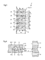
- FIG. 1 shows a vertical and schematic longitudinal sectional view of a headbox 1 for a machine for producing a fibrous web 3 from a pulp suspension 2 (arrow).
- the illustrated headbox 1 can of course also be designed as a multilayer headbox, which uses at least two different pulp suspensions for producing the fibrous web 3.
- the fibrous web 3 can be in particular a paper, board or tissue web.
- the headbox 1 has a feeding device 4 feeding the pulp suspension 2 (arrow) in the form of a transverse dividing pipe 5.1 known to the person skilled in the art.
- the feeder 4 is followed downstream by a Verteilrohrlochplatte 6, which has a plurality of arranged in rows Z and in columns S channels 7.
- the individual means 9 for preferably controllable metered addition comprises in each case a plurality of metering channels 11 having a respective metering channel opening 11.0 and opening at different heights and connected to a common supply channel 12 (cf. FIG. 4 ).
- the individual means 9 for preferably controllable metered addition is designed as a metering blade 9.1.
- a turbulence generating means 13 Downstream of the intermediate channel 8 is a turbulence generating means 13 having a plurality of flow channels 14 arranged in rows Z and columns S.
- the pulp suspension 2 (arrow) in the turbulence generating means 13 is divided into pulp suspension partial streams and after leaving the Turbulence generating means in a machine-width chamber 15 in a design of a nozzle gap 17 having headbox nozzle 16 merged again to allow the formation of a machine-width fibrous web 3.
- the flow channels 14 are in a known manner preferably as thin-walled turbulence tubes and / or turbulence tube inserts with at least in sections formed constant, at least partially diverging, at least partially converging and / or discontinuous cross-sectional areas.
- separating elements in particular a blade may be arranged. If a plurality of separating elements, in particular lamellae, are arranged in the headbox nozzle 16, they can have different lengths and possibly also different properties, such as surface contours and the like.
- the headbox 16 may be provided on the outlet side at least one side with a dashed line indicated aperture 18.
- the head box 1 has a system pressure loss, which essentially consists of a first pressure loss ⁇ p1 between the feed device 4 and the intermediate channel 8 and a second pressure loss ⁇ p2 in the turbulence generating means 13, wherein the second pressure loss ⁇ p2 and the first pressure loss ⁇ p1 in a ratio in a range from 8: 1 to 1: 1, preferably from 4: 1 to 1: 1, in particular from 2: 1 to 1: 1.
- the second pressure loss ⁇ p2 in the turbulence generating means 13 is in a range of 0.1 to 1.5 bar, preferably 0.2 to 1.0 bar, in particular 0.3 to 0.5 bar.
- the distribution well plate 6 is provided with hydraulic elements 19 for pressure recovery, such as diffusers, stage diffusers or the like (see. FIG. 3 ).
- the pulp suspension 2 fed to the feed device 4 is supplied exclusively to the downstream channels 7 of the distribution well plate 6.
- the headbox 1 thus has no recirculation for it by means of the feeder 4 supplied pulp suspension 2.
- the opening at different heights Zudosierkanäle 11 of the metering 9.1 trained means 9 for preferably regulated / controllable metering are arranged at equal intervals a and the respectively associated with the common supply channel 12 Zudosierkanal 11 of the means 9 for preferably adjustable / controllable metering has a circular cross-sectional area 11.Q with a diameter eleventh D from 2 to 10 mm, preferably from 4 to 6 mm.
- the common supply channel 12 of the means 9 for preferably controllable metered addition has a circular cross-sectional area 12.Q with a diameter 12.D of 6 to 20 mm, preferably from 10 to 15 mm (see. FIG. 4 ).
- the means 9, preferably designed as a metering blade 9.1, for preferably controllable metering has a length 9.L in the range of 60 to 350 mm, preferably 100 to 250 mm, and a height 9 depending on the height of the intermediate chamber of the headbox 1. H in the range of 50 to 300 mm, preferably from 75 to 250 mm.
- the means 9 for preferably controllable metered addition have a preferably equal pitch T in the width direction of the headbox 1 in the range of 10 to 100 mm, preferably 25, 33, 50 or 66 mm.
- the metering blade 9.1 is described and shown in the German patent application (Applicant's file: HPA14265 DE and Applicant's working title: "MJ II-DoS-TE geometry") with the same filing date as the present patent application.
- the metering opening 11.O of the means 9 for preferably controllable metered addition of the fluid 10 in partial fluid streams 10.T (arrows) into the pulp suspension 2 to the turbulence generating means 13 has a vertical distance A in the range of 2 to 100 mm, preferably from 3 to 50 mm, in particular from 5 to 30 mm (cf. FIG. 4 ).
- FIG. 2 shows a vertical and schematic longitudinal sectional view of a second embodiment according to the invention of a headbox 1 for a machine for producing a fibrous web 3 from at least one fibrous suspension 2.
- the basic structure of this headbox 1 substantially corresponds to the basic structure of the in the FIG. 1 Headbox 1 shown schematically, so that reference is also made to this description of figures.
- the feed device 4 of this headbox 1 comprises a plurality of hoses 5.21 having central distributor 5.2, the tubes are connected to the lines 5.21 in rows Z and in columns S channels 7 of the distribution well plate 6.
- the known to the expert central distributor 5.2 is commonly referred to as a round distributor.
- the distribution well plate 6 is in turn provided with hydraulic elements 19 for pressure recovery, such as diffusers, stage diffusers or the like (see. FIG. 3 )
- this headbox 1 has due to its design, a system pressure drop, which consists essentially of a first pressure loss ⁇ p1 between the feeder 4 and the intermediate channel 8 and a second pressure loss .DELTA.p2 in the turbulence generating means wherein the second pressure loss .DELTA.p2 and the first pressure loss .DELTA.P1 in one Ratio in a range from 8: 1 to 1: 1, preferably from 4: 1 to 1: 1, in particular from 2: 1 to 1: 1, lie.
- the second pressure loss ⁇ p 2 in the turbulence generating means 13 is in a range of 0.1 to 1.5 bar, preferably from 0.2 to 1.0 bar, in particular from 0.3 to 0.5 bar.
- separating elements in particular a blade may be arranged. If a plurality of separating elements, in particular lamellae, are arranged in the headbox nozzle 16, they can have different lengths and possibly also different properties, such as surface contours and the like.
- FIG. 3 shows a vertical and schematic longitudinal sectional view of a Verteillochlochplatte 6 of the headbox 1 of the invention for a machine for producing a fibrous web from at least one pulp suspension with five channels 7 with different channel cross-sections 7.Q.
- the distribution well plate 6 has five rows Z1 to Z5 on channels 7 and a plurality of columns S on channels 7. All channels 7 have a consistently round channel cross section 7.Q, but in different shapes and configurations. Also, all channels 7 are provided on the inlet side with a respective intake chamfer 20 known to those skilled in the art.
- the channels 7 of the two upper lines Z4, Z5 initially have a constant channel cross section 7.Q, which ultimately experiences a continuous extension 21, in particular a cone 21.1 with a cone angle a of ⁇ 30 °.
- the channels 7 of the middle row Z3 initially again have a constant channel cross section 7.Q, which ultimately experiences two jump-like extensions 22, in particular step jumps 22.1, 22.2.
- the channels 7 of the two lower rows Z1, Z2 initially again have a constant channel cross section 7.Q, which ultimately only experiences a sudden expansion 22, in particular a step jump 22.1.
- Each individual channel 7 of the distribution well plate 6 thus has at least initially a round channel cross section 7.Q with a channel diameter 7.D and then forms a hydraulic element 19 for pressure recovery due to at least one extension 21, 22 from.
- the mean channel diameter 7.DM of the channel 7 of the distribution well plate 6 and the length 6.L of the distribution well plate 6 are in a ratio of 1: 2 to 1:10, preferably from 1: 3 to 1: 8, in particular from 1: 4 to 1: 5.
- FIG. 4 shows a schematic detail of the means 9 for preferably controllable metered addition of the fluid 10 in partial fluid streams 10.T (arrow).
- the metering channels 11 of the means 9 for preferably controllable metering, which discharge at different heights, are arranged at equal distances a and the metering channel 11 of the means 9 for preferably controllable metering connected to the common supply channel 12 has a circular cross-sectional area 11. Q with a diameter 11.D of 2 to 10 mm, preferably from 4 to 6 mm.
- the common supply channel 12 of the means 9 for preferably controllable metered addition has a circular cross-sectional area 12.Q with a diameter 12.D of 6 to 20 mm, preferably from 10 to 15 mm.
- the impact point P of the opening center line 11.M of the individual metering opening 11.O of the metering channel 11 on the turbulence generating means 13 is approximately centrally, preferably centrally between the two column planes of two adjacent flow channels 14 of the turbulence generating means 13th
- the headbox 1 of the FIGS. 1 to 4 flowing fluid 10 consists at least of water, in particular white water or clear water, or from at least one pulp suspension whose concentration differs from the average concentration of at least one in the headbox 1 flowing pulp suspension 2.
- the headbox 1 shown and described in each case in the figures is particularly suitable for use in a machine for producing a fibrous web 3, in particular paper or board web, from at least one fibrous stock suspension 2.
- a headbox of the type mentioned above is improved by the invention so that the aforementioned disadvantages of the prior art as far as possible, preferably completely eliminated.
- the pressure loss for preferably uniform distribution of the pulp suspension is distributed as low as possible and optimal.
- the energy consumption of the headbox is significantly reduced, improves the stability of the fiber orientation (transverse) profile and reduces the consumption of chemicals, in particular retention agents.
Landscapes
- Paper (AREA)
- Nonwoven Fabrics (AREA)
Claims (11)
- Caisse de tête (1) pour une machine de fabrication d'une bande fibreuse (3), en particulier d'une bande de papier ou de carton, constituée d'au moins une suspension fibreuse (2), avec un dispositif d'alimentation (4, 5.1 ; 4, 5.2) acheminant l'au moins une suspension fibreuse (2) avec une plaque perforée de tubes de distribution (6) se raccordant en aval et présentant une pluralité de canaux (7) disposés en lignes (Z) et en colonnes (S), avec un canal intermédiaire (8) situé en aval de celle-ci, s'étendant sur la largeur (B) de la caisse de tête (1), avec plusieurs moyens (9, 9.1) espacés les uns des autres dans la direction de la largeur de la caisse de tête (1), pour l'ajout par dosage de préférence réglable/commandable d'un fluide (10) en flux partiels de fluide (10.T) dans l'au moins une suspension fibreuse (2), le moyen individuel (9, 9.1) comprenant à chaque fois plusieurs canaux d'ajout par dosage (11) présentant une ouverture respective (11.O) de canal d'ajout par dosage et une ligne médiane de l'ouverture (11.M) débouchant à différentes hauteurs et connectés à un canal d'alimentation commun (12), avec un moyen de génération de turbulences (13) disposé en aval avec une pluralité de canaux d'écoulement (14) disposés en lignes (Z) et en colonnes (S), et avec une buse de caisse de tête (16) se raccordant directement au moyen de génération de turbulences (13) et présentant une fente de buse (17),
caractérisée en ce
qu'elle présente, du fait de sa configuration, une perte de pression du système qui se compose essentiellement d'une première perte de pression (Δp1) entre le dispositif d'alimentation (4, 5.1 ; 4, 5.2) et le canal intermédiaire (8) et d'une deuxième perte de pression (Δp2) dans le moyen de génération de turbulences (13), la deuxième perte de pression (Δp2) et la première perte de pression (Δp1) se situant dans un rapport de l'ordre de 8:1 à 1:1, de préférence de 4:1 à 1:1, notamment de 2:1 à 1:1. - Caisse de tête (1) selon la revendication 1,
caractérisée en ce que
la deuxième perte de pression (Δp2) dans le moyen de génération de turbulences (13) se situe dans une plage de 0,1 à 1,5 bar, de préférence de 0,2 à 1,0 bar, notamment de 0,3 à 0,5 bar. - Caisse de tête (1) selon la revendication 1 ou 2,
caractérisée en ce que
le dispositif d'alimentation (4) comprend un tube de distribution transversal (5.1) monté sur la plaque perforée de tubes de distribution (6) et en ce que la plaque perforée de tubes de distribution (6) est pourvue d'éléments hydrauliques (19) pour la récupération de la pression, par exemple des diffuseurs (21), des diffuseurs étagés (22) ou similaires. - Caisse de tête (1) selon la revendication 1 ou 2,
caractérisée en ce que
le dispositif d'alimentation (4) comprend un distributeur central (5.2) présentant une pluralité de tuyaux souples (5.21), dont les tuyaux souples (5.21) sont connectés aux canaux (7) de la plaque perforée de tubes de distribution (6). - Caisse de tête (1) selon la revendication 4,
caractérisée en ce que
la pluralité de tuyaux souples (5.21) est pourvue d'éléments hydrauliques (19) pour la récupération de la pression, par exemple de diffuseurs (21), de diffuseurs étagés (22), ou similaires. - Caisse de tête (1) selon l'une quelconque des revendications précédentes,
caractérisée en ce que
l'au moins une suspension fibreuse (2) acheminée au dispositif d'alimentation (4, 5.1) est acheminée exclusivement aux canaux (7) de la plaque perforée de tubes de distribution (6) se raccordant en aval. - Caisse de tête (1) selon l'une quelconque des revendications précédentes,
caractérisée en ce que
le point de contact (P) de la ligne médiane de l'ouverture (11.M) de l'ouverture individuelle (11.O) d'ajout par dosage se situe sur le moyen de génération de turbulences (13) approximativement au centre, de préférence au centre entre les deux plans des colonnes de deux canaux d'écoulement adjacents (14). - Caisse de tête (1) selon l'une quelconque des revendications précédentes,
caractérisée en ce que
l'ouverture d'ajout par dosage du moyen (9, 9.1) pour l'ajout par dosage de préférence réglable/commandable du fluide (10) en flux partiels de fluide (10.T) dans l'au moins une suspension fibreuse (2) au moyen de génération de turbulences (13) présente une distance verticale (A) de l'ordre de 2 à 100 mm, de préférence de 3 à 50 mm, notamment de 5 à 30 mm. - Caisse de tête (1) selon l'une quelconque des revendications précédentes,
caractérisée en ce que
le moyen respectif (9) pour l'ajout par dosage de préférence réglable/commandable du fluide (10) en flux partiels de fluide (10.T) dans l'au moins une suspension fibreuse (2) comprend une lame de dosage (9.1). - Caisse de tête (1) selon l'une quelconque des revendications précédentes,
caractérisée en ce que
le fluide (10) se compose d'eau, notamment d'eau blanche ou d'eau claire, ou au moins d'une suspension fibreuse dont la concentration est différente de la concentration moyenne de l'au moins une suspension fibreuse (2) s'écoulant dans la caisse de tête (1). - Machine de fabrication d'une bande fibreuse (3), en particulier d'une bande de papier ou de carton, comprenant au moins une caisse de tête (1) selon l'une quelconque des revendications 1 à 10.
Applications Claiming Priority (2)
| Application Number | Priority Date | Filing Date | Title |
|---|---|---|---|
| DE102008054896A DE102008054896A1 (de) | 2008-12-18 | 2008-12-18 | Stoffauflauf für eine Maschine zur Herstellung einer Faserstoffbahn |
| PCT/EP2009/063846 WO2010069653A1 (fr) | 2008-12-18 | 2009-10-22 | Caisse de tête pour machine de fabrication d'une bande de matière fibreuse |
Publications (2)
| Publication Number | Publication Date |
|---|---|
| EP2379800A1 EP2379800A1 (fr) | 2011-10-26 |
| EP2379800B1 true EP2379800B1 (fr) | 2012-12-12 |
Family
ID=41479344
Family Applications (1)
| Application Number | Title | Priority Date | Filing Date |
|---|---|---|---|
| EP09740126A Active EP2379800B1 (fr) | 2008-12-18 | 2009-10-22 | Caisse de tête pour machine de fabrication d'une bande de matière fibreuse |
Country Status (5)
| Country | Link |
|---|---|
| US (1) | US8236137B2 (fr) |
| EP (1) | EP2379800B1 (fr) |
| CN (1) | CN102216523B (fr) |
| DE (1) | DE102008054896A1 (fr) |
| WO (1) | WO2010069653A1 (fr) |
Families Citing this family (11)
| Publication number | Priority date | Publication date | Assignee | Title |
|---|---|---|---|---|
| DE102010001555A1 (de) | 2010-02-03 | 2011-08-04 | Voith Patent GmbH, 89522 | Ventil zum Regulieren eines Fluidstroms |
| DE102010001557A1 (de) | 2010-02-03 | 2011-08-04 | Voith Patent GmbH, 89522 | Ventil zum Regulieren eines Fluidstroms |
| DE102010028403A1 (de) | 2010-04-30 | 2011-11-03 | Voith Patent Gmbh | Ventil zum Regulieren eines Fluidstroms |
| DE102010028404A1 (de) | 2010-04-30 | 2011-11-03 | Voith Patent Gmbh | Ventil zum Regulieren eines Fluidstroms |
| DE102010028408A1 (de) | 2010-04-30 | 2011-11-03 | Voith Patent Gmbh | Ventil zum Regulieren eines Fluidstroms |
| DE102010030352A1 (de) | 2010-06-22 | 2011-12-22 | Voith Patent Gmbh | Stoffauflauf für eine Maschine zur Herstellung einer Faserstoffbahn |
| DE102010038891A1 (de) | 2010-08-04 | 2012-02-09 | Voith Patent Gmbh | Stoffauflauf für eine Maschine zur Herstellung einer Faserstoffbahn |
| DE102011079715A1 (de) | 2011-07-25 | 2013-01-31 | Voith Patent Gmbh | Stoffauflauf für eine Maschine zur Herstellung einer Faserstoffbahn |
| DE102011083085A1 (de) | 2011-09-21 | 2013-03-21 | Voith Patent Gmbh | Stoffauflauf für eine Maschine zur Herstellung einer Faserstoffbahn |
| US8871059B2 (en) * | 2012-02-16 | 2014-10-28 | International Paper Company | Methods and apparatus for forming fluff pulp sheets |
| CN103422384B (zh) * | 2013-08-08 | 2015-04-22 | 华南理工大学 | 一种可进行流场测量和可视化研究的水力式实验流浆箱 |
Family Cites Families (18)
| Publication number | Priority date | Publication date | Assignee | Title |
|---|---|---|---|---|
| DE4213707A1 (de) * | 1992-04-25 | 1993-10-28 | Escher Wyss Gmbh | Stoffauflaufeinrichtung für eine Papiermaschine |
| DE4320243C2 (de) * | 1993-06-18 | 1996-02-22 | Voith Sulzer Papiermasch Gmbh | Stoffauflauf für eine Papiermaschine |
| DE4416898C2 (de) | 1994-05-13 | 1996-03-28 | Voith Sulzer Papiermasch Gmbh | Stoffauflauf für eine Papiermaschine mit lokaler Zumischung von Fluid |
| ATE158356T1 (de) * | 1994-05-13 | 1997-10-15 | Voith Sulzer Papiermasch Gmbh | Stoffauflauf für eine papiermaschine mit lokaler zumischung von fluid |
| DE4416909C2 (de) | 1994-05-13 | 1997-12-11 | Voith Sulzer Papiermasch Gmbh | Stoffauflauf für eine Papiermaschine |
| DE4416899C2 (de) | 1994-05-13 | 1997-12-18 | Voith Sulzer Papiermasch Gmbh | Verfahren zur lokalen Zumischung von Fluid in einen Stoffauflauf sowie Vorrichtung zu seiner Ausführung |
| DE4437180C2 (de) * | 1994-10-18 | 1997-03-20 | Voith Sulzer Papiermasch Gmbh | Verfahren zur Herstellung eines Stoffauflaufes und Zwischenteil eines Stoffaufllaufes einer Papier- oder Kartonmaschine |
| WO1997039182A1 (fr) * | 1996-04-18 | 1997-10-23 | Valmet Corporation | Procede continu de regulation generale de la caisse de tete et/ou du formeur d'une machine a papier ou a carton |
| EP0824157B1 (fr) | 1996-08-14 | 2001-12-05 | Voith Paper Patent GmbH | Caisse de tête et procédé pour la répartition d'une suspension fibreuse dans la caisse de tête d'une machine à papier |
| FI110704B (fi) * | 1996-10-18 | 2003-03-14 | Metso Paper Inc | Monikerrosperälaatikon massansyöttöjärjestelmä ja menetelmä monikerrosperälaatikkokäytössä |
| FI115645B (fi) * | 1997-01-14 | 2005-06-15 | Metso Paper Inc | Paperikoneen perälaatikko, jossa on reunasyöttöjärjestelyt |
| DE19926805A1 (de) * | 1999-06-12 | 2000-12-14 | Voith Sulzer Papiertech Patent | Stoffauflauf mit Fluidzudosierung |
| DE10102087A1 (de) * | 2001-01-18 | 2001-06-13 | Voith Paper Patent Gmbh | Verfahren und Turbulenzerzeuger eines Stoffauflaufs zur Einstellung der Faserorientierung einer Faserstoffsuspension in einer Papier- oder Kartonmaschine |
| DE10245154A1 (de) | 2002-09-27 | 2004-04-15 | Voith Paper Patent Gmbh | Stoffauflauf |
| CN101589296B (zh) * | 2006-02-01 | 2015-04-22 | 美商艾斯登强生股份有限公司 | 造纸机送浆系统及浆料的定量黏度规划方法 |
| DE102008043145A1 (de) | 2008-10-24 | 2010-04-29 | Voith Patent Gmbh | Zweischichtenstoffauflauf für eine Maschine zur Herstellung einer zweischichtigen Faserstoffbahn |
| EP2199459A1 (fr) | 2008-12-16 | 2010-06-23 | Voith Patent GmbH | Système de formation de feuille pour une machine destinée à la fabrication d'une bande de matière fibreuse multicouche |
| DE102008054898A1 (de) | 2008-12-18 | 2010-06-24 | Voith Patent Gmbh | Stoffauflauf für eine Maschine zur Herstellung einer Faserstoffbahn |
-
2008
- 2008-12-18 DE DE102008054896A patent/DE102008054896A1/de not_active Withdrawn
-
2009
- 2009-10-22 EP EP09740126A patent/EP2379800B1/fr active Active
- 2009-10-22 CN CN200980145601.9A patent/CN102216523B/zh active Active
- 2009-10-22 WO PCT/EP2009/063846 patent/WO2010069653A1/fr active Application Filing
-
2011
- 2011-05-06 US US13/102,688 patent/US8236137B2/en not_active Expired - Fee Related
Also Published As
| Publication number | Publication date |
|---|---|
| DE102008054896A1 (de) | 2010-07-01 |
| US20110265968A1 (en) | 2011-11-03 |
| CN102216523A (zh) | 2011-10-12 |
| EP2379800A1 (fr) | 2011-10-26 |
| US8236137B2 (en) | 2012-08-07 |
| WO2010069653A1 (fr) | 2010-06-24 |
| CN102216523B (zh) | 2014-01-01 |
Similar Documents
| Publication | Publication Date | Title |
|---|---|---|
| EP2379800B1 (fr) | Caisse de tête pour machine de fabrication d'une bande de matière fibreuse | |
| EP2379799B1 (fr) | Caisson de tête pour machine de fabrication d'une bande de matière fibreuse | |
| EP2379803B1 (fr) | Caisse de tête d'arrivée de pâte pour une machine de production d'une bande continue de matière fibreuse | |
| EP2379802A1 (fr) | Caisson de tête pour machine de fabrication d'une bande de matière fibreuse | |
| DE102008054893A1 (de) | Stoffauflauf für eine Maschine zur Herstellung einer Faserstoffbahn | |
| WO2010069652A1 (fr) | Caisson de tête pour machine de fabrication d'une bande de matière fibreuse | |
| EP2531645A1 (fr) | Caisse de tête pour une machine de production d'une bande de matière fibreuse | |
| EP2464782A2 (fr) | Caisse de tête pour une machine servant à fabriquer une bande de matière fibreuse et machine | |
| EP2454411A1 (fr) | Caisse de tête pour une machine de fabrication d une bande de matière fibreuse | |
| EP1619298A2 (fr) | Caisse de tête d'une machine pour fabriquer une bande fibreuse, en particulier une bande de papier ou de carton | |
| EP2487292A1 (fr) | Caisse de tête pour une machine destinée à la fabrication d'une bande de matière fibreuse | |
| EP1676950B1 (fr) | Caisse de tête pour machine de fabrication d'une bande fibreuse, une bande de papier ou de carton | |
| EP2585633B1 (fr) | Caisse de tête pour une machine de production d'une bande de matière fibreuse | |
| EP2531647B1 (fr) | Caisse de tête et unité de formation de feuille comprenant une caisse de tête | |
| DE102018120162A1 (de) | Stoffauflauf | |
| EP1693508A1 (fr) | Caisse de tête d'une machine pour fabriquer une bande de matière fibreuse et procédé pour fabriquer une bande de matière fibreuse | |
| EP1793035A2 (fr) | Caisse de tête d'une machine de fabrication d'une bande fibreuse | |
| DE102007037006A1 (de) | Stoffauflauf einer Maschine zur Herstellung einer Faserstoffbahn | |
| WO2011095582A1 (fr) | Caisse de tête et unité de formation de feuille comprenant une caisse de tête | |
| DE102011003850A1 (de) | Stoffauflauf für eine Maschine zur Herstellung einer Faserstoffbahn | |
| DE10245156A1 (de) | Stoffauflauf | |
| DE102010038891A1 (de) | Stoffauflauf für eine Maschine zur Herstellung einer Faserstoffbahn |
Legal Events
| Date | Code | Title | Description |
|---|---|---|---|
| PUAI | Public reference made under article 153(3) epc to a published international application that has entered the european phase |
Free format text: ORIGINAL CODE: 0009012 |
|
| 17P | Request for examination filed |
Effective date: 20110718 |
|
| AK | Designated contracting states |
Kind code of ref document: A1 Designated state(s): AT BE BG CH CY CZ DE DK EE ES FI FR GB GR HR HU IE IS IT LI LT LU LV MC MK MT NL NO PL PT RO SE SI SK SM TR |
|
| DAX | Request for extension of the european patent (deleted) | ||
| GRAP | Despatch of communication of intention to grant a patent |
Free format text: ORIGINAL CODE: EPIDOSNIGR1 |
|
| GRAP | Despatch of communication of intention to grant a patent |
Free format text: ORIGINAL CODE: EPIDOSNIGR1 |
|
| GRAS | Grant fee paid |
Free format text: ORIGINAL CODE: EPIDOSNIGR3 |
|
| GRAA | (expected) grant |
Free format text: ORIGINAL CODE: 0009210 |
|
| AK | Designated contracting states |
Kind code of ref document: B1 Designated state(s): AT BE BG CH CY CZ DE DK EE ES FI FR GB GR HR HU IE IS IT LI LT LU LV MC MK MT NL NO PL PT RO SE SI SK SM TR |
|
| REG | Reference to a national code |
Ref country code: GB Ref legal event code: FG4D Free format text: NOT ENGLISH |
|
| REG | Reference to a national code |
Ref country code: CH Ref legal event code: EP |
|
| REG | Reference to a national code |
Ref country code: AT Ref legal event code: REF Ref document number: 588400 Country of ref document: AT Kind code of ref document: T Effective date: 20121215 |
|
| REG | Reference to a national code |
Ref country code: IE Ref legal event code: FG4D Free format text: LANGUAGE OF EP DOCUMENT: GERMAN |
|
| REG | Reference to a national code |
Ref country code: DE Ref legal event code: R096 Ref document number: 502009005675 Country of ref document: DE Effective date: 20130207 |
|
| PG25 | Lapsed in a contracting state [announced via postgrant information from national office to epo] |
Ref country code: SE Free format text: LAPSE BECAUSE OF FAILURE TO SUBMIT A TRANSLATION OF THE DESCRIPTION OR TO PAY THE FEE WITHIN THE PRESCRIBED TIME-LIMIT Effective date: 20121212 Ref country code: LT Free format text: LAPSE BECAUSE OF FAILURE TO SUBMIT A TRANSLATION OF THE DESCRIPTION OR TO PAY THE FEE WITHIN THE PRESCRIBED TIME-LIMIT Effective date: 20121212 Ref country code: ES Free format text: LAPSE BECAUSE OF FAILURE TO SUBMIT A TRANSLATION OF THE DESCRIPTION OR TO PAY THE FEE WITHIN THE PRESCRIBED TIME-LIMIT Effective date: 20130323 Ref country code: NO Free format text: LAPSE BECAUSE OF FAILURE TO SUBMIT A TRANSLATION OF THE DESCRIPTION OR TO PAY THE FEE WITHIN THE PRESCRIBED TIME-LIMIT Effective date: 20130312 |
|
| REG | Reference to a national code |
Ref country code: NL Ref legal event code: VDEP Effective date: 20121212 |
|
| REG | Reference to a national code |
Ref country code: LT Ref legal event code: MG4D |
|
| PG25 | Lapsed in a contracting state [announced via postgrant information from national office to epo] |
Ref country code: SI Free format text: LAPSE BECAUSE OF FAILURE TO SUBMIT A TRANSLATION OF THE DESCRIPTION OR TO PAY THE FEE WITHIN THE PRESCRIBED TIME-LIMIT Effective date: 20121212 Ref country code: LV Free format text: LAPSE BECAUSE OF FAILURE TO SUBMIT A TRANSLATION OF THE DESCRIPTION OR TO PAY THE FEE WITHIN THE PRESCRIBED TIME-LIMIT Effective date: 20121212 Ref country code: GR Free format text: LAPSE BECAUSE OF FAILURE TO SUBMIT A TRANSLATION OF THE DESCRIPTION OR TO PAY THE FEE WITHIN THE PRESCRIBED TIME-LIMIT Effective date: 20130313 |
|
| PG25 | Lapsed in a contracting state [announced via postgrant information from national office to epo] |
Ref country code: BG Free format text: LAPSE BECAUSE OF FAILURE TO SUBMIT A TRANSLATION OF THE DESCRIPTION OR TO PAY THE FEE WITHIN THE PRESCRIBED TIME-LIMIT Effective date: 20130312 Ref country code: EE Free format text: LAPSE BECAUSE OF FAILURE TO SUBMIT A TRANSLATION OF THE DESCRIPTION OR TO PAY THE FEE WITHIN THE PRESCRIBED TIME-LIMIT Effective date: 20121212 Ref country code: SK Free format text: LAPSE BECAUSE OF FAILURE TO SUBMIT A TRANSLATION OF THE DESCRIPTION OR TO PAY THE FEE WITHIN THE PRESCRIBED TIME-LIMIT Effective date: 20121212 Ref country code: CZ Free format text: LAPSE BECAUSE OF FAILURE TO SUBMIT A TRANSLATION OF THE DESCRIPTION OR TO PAY THE FEE WITHIN THE PRESCRIBED TIME-LIMIT Effective date: 20121212 Ref country code: IS Free format text: LAPSE BECAUSE OF FAILURE TO SUBMIT A TRANSLATION OF THE DESCRIPTION OR TO PAY THE FEE WITHIN THE PRESCRIBED TIME-LIMIT Effective date: 20130412 |
|
| PG25 | Lapsed in a contracting state [announced via postgrant information from national office to epo] |
Ref country code: PL Free format text: LAPSE BECAUSE OF FAILURE TO SUBMIT A TRANSLATION OF THE DESCRIPTION OR TO PAY THE FEE WITHIN THE PRESCRIBED TIME-LIMIT Effective date: 20121212 Ref country code: RO Free format text: LAPSE BECAUSE OF FAILURE TO SUBMIT A TRANSLATION OF THE DESCRIPTION OR TO PAY THE FEE WITHIN THE PRESCRIBED TIME-LIMIT Effective date: 20121212 Ref country code: PT Free format text: LAPSE BECAUSE OF FAILURE TO SUBMIT A TRANSLATION OF THE DESCRIPTION OR TO PAY THE FEE WITHIN THE PRESCRIBED TIME-LIMIT Effective date: 20130412 Ref country code: NL Free format text: LAPSE BECAUSE OF FAILURE TO SUBMIT A TRANSLATION OF THE DESCRIPTION OR TO PAY THE FEE WITHIN THE PRESCRIBED TIME-LIMIT Effective date: 20121212 |
|
| PLBE | No opposition filed within time limit |
Free format text: ORIGINAL CODE: 0009261 |
|
| STAA | Information on the status of an ep patent application or granted ep patent |
Free format text: STATUS: NO OPPOSITION FILED WITHIN TIME LIMIT |
|
| PG25 | Lapsed in a contracting state [announced via postgrant information from national office to epo] |
Ref country code: DK Free format text: LAPSE BECAUSE OF FAILURE TO SUBMIT A TRANSLATION OF THE DESCRIPTION OR TO PAY THE FEE WITHIN THE PRESCRIBED TIME-LIMIT Effective date: 20121212 |
|
| 26N | No opposition filed |
Effective date: 20130913 |
|
| PG25 | Lapsed in a contracting state [announced via postgrant information from national office to epo] |
Ref country code: CY Free format text: LAPSE BECAUSE OF FAILURE TO SUBMIT A TRANSLATION OF THE DESCRIPTION OR TO PAY THE FEE WITHIN THE PRESCRIBED TIME-LIMIT Effective date: 20121212 Ref country code: HR Free format text: LAPSE BECAUSE OF FAILURE TO SUBMIT A TRANSLATION OF THE DESCRIPTION OR TO PAY THE FEE WITHIN THE PRESCRIBED TIME-LIMIT Effective date: 20121212 |
|
| REG | Reference to a national code |
Ref country code: DE Ref legal event code: R097 Ref document number: 502009005675 Country of ref document: DE Effective date: 20130913 |
|
| BERE | Be: lapsed |
Owner name: VOITH PATENT G.M.B.H. Effective date: 20131031 |
|
| PG25 | Lapsed in a contracting state [announced via postgrant information from national office to epo] |
Ref country code: MC Free format text: LAPSE BECAUSE OF FAILURE TO SUBMIT A TRANSLATION OF THE DESCRIPTION OR TO PAY THE FEE WITHIN THE PRESCRIBED TIME-LIMIT Effective date: 20121212 |
|
| REG | Reference to a national code |
Ref country code: CH Ref legal event code: PL |
|
| GBPC | Gb: european patent ceased through non-payment of renewal fee |
Effective date: 20131022 |
|
| REG | Reference to a national code |
Ref country code: IE Ref legal event code: MM4A |
|
| PG25 | Lapsed in a contracting state [announced via postgrant information from national office to epo] |
Ref country code: LI Free format text: LAPSE BECAUSE OF NON-PAYMENT OF DUE FEES Effective date: 20131031 Ref country code: GB Free format text: LAPSE BECAUSE OF NON-PAYMENT OF DUE FEES Effective date: 20131022 Ref country code: CH Free format text: LAPSE BECAUSE OF NON-PAYMENT OF DUE FEES Effective date: 20131031 |
|
| REG | Reference to a national code |
Ref country code: FR Ref legal event code: ST Effective date: 20140630 |
|
| PG25 | Lapsed in a contracting state [announced via postgrant information from national office to epo] |
Ref country code: FR Free format text: LAPSE BECAUSE OF NON-PAYMENT OF DUE FEES Effective date: 20131031 |
|
| PG25 | Lapsed in a contracting state [announced via postgrant information from national office to epo] |
Ref country code: BE Free format text: LAPSE BECAUSE OF NON-PAYMENT OF DUE FEES Effective date: 20131031 |
|
| PG25 | Lapsed in a contracting state [announced via postgrant information from national office to epo] |
Ref country code: IE Free format text: LAPSE BECAUSE OF NON-PAYMENT OF DUE FEES Effective date: 20131022 |
|
| PG25 | Lapsed in a contracting state [announced via postgrant information from national office to epo] |
Ref country code: SM Free format text: LAPSE BECAUSE OF FAILURE TO SUBMIT A TRANSLATION OF THE DESCRIPTION OR TO PAY THE FEE WITHIN THE PRESCRIBED TIME-LIMIT Effective date: 20121212 |
|
| PG25 | Lapsed in a contracting state [announced via postgrant information from national office to epo] |
Ref country code: TR Free format text: LAPSE BECAUSE OF FAILURE TO SUBMIT A TRANSLATION OF THE DESCRIPTION OR TO PAY THE FEE WITHIN THE PRESCRIBED TIME-LIMIT Effective date: 20121212 |
|
| PG25 | Lapsed in a contracting state [announced via postgrant information from national office to epo] |
Ref country code: LU Free format text: LAPSE BECAUSE OF NON-PAYMENT OF DUE FEES Effective date: 20131022 Ref country code: MK Free format text: LAPSE BECAUSE OF FAILURE TO SUBMIT A TRANSLATION OF THE DESCRIPTION OR TO PAY THE FEE WITHIN THE PRESCRIBED TIME-LIMIT Effective date: 20121212 Ref country code: HU Free format text: LAPSE BECAUSE OF FAILURE TO SUBMIT A TRANSLATION OF THE DESCRIPTION OR TO PAY THE FEE WITHIN THE PRESCRIBED TIME-LIMIT; INVALID AB INITIO Effective date: 20091022 |
|
| PG25 | Lapsed in a contracting state [announced via postgrant information from national office to epo] |
Ref country code: MT Free format text: LAPSE BECAUSE OF FAILURE TO SUBMIT A TRANSLATION OF THE DESCRIPTION OR TO PAY THE FEE WITHIN THE PRESCRIBED TIME-LIMIT Effective date: 20121212 |
|
| PGFP | Annual fee paid to national office [announced via postgrant information from national office to epo] |
Ref country code: IT Payment date: 20231026 Year of fee payment: 15 Ref country code: FI Payment date: 20231019 Year of fee payment: 15 Ref country code: DE Payment date: 20231020 Year of fee payment: 15 Ref country code: AT Payment date: 20231020 Year of fee payment: 15 |