EP0826818A2 - Process and apparatus for adjusting the consistency and fibre orientation profile in a headbox - Google Patents
Process and apparatus for adjusting the consistency and fibre orientation profile in a headbox Download PDFInfo
- Publication number
- EP0826818A2 EP0826818A2 EP97111794A EP97111794A EP0826818A2 EP 0826818 A2 EP0826818 A2 EP 0826818A2 EP 97111794 A EP97111794 A EP 97111794A EP 97111794 A EP97111794 A EP 97111794A EP 0826818 A2 EP0826818 A2 EP 0826818A2
- Authority
- EP
- European Patent Office
- Prior art keywords
- flow
- turbulence
- suspension
- headbox
- angle
- Prior art date
- Legal status (The legal status is an assumption and is not a legal conclusion. Google has not performed a legal analysis and makes no representation as to the accuracy of the status listed.)
- Withdrawn
Links
Images


Classifications
-
- D—TEXTILES; PAPER
- D21—PAPER-MAKING; PRODUCTION OF CELLULOSE
- D21F—PAPER-MAKING MACHINES; METHODS OF PRODUCING PAPER THEREON
- D21F1/00—Wet end of machines for making continuous webs of paper
- D21F1/02—Head boxes of Fourdrinier machines
- D21F1/022—Means for injecting material into flow within the headbox
-
- D—TEXTILES; PAPER
- D21—PAPER-MAKING; PRODUCTION OF CELLULOSE
- D21F—PAPER-MAKING MACHINES; METHODS OF PRODUCING PAPER THEREON
- D21F1/00—Wet end of machines for making continuous webs of paper
- D21F1/02—Head boxes of Fourdrinier machines
-
- D—TEXTILES; PAPER
- D21—PAPER-MAKING; PRODUCTION OF CELLULOSE
- D21F—PAPER-MAKING MACHINES; METHODS OF PRODUCING PAPER THEREON
- D21F1/00—Wet end of machines for making continuous webs of paper
- D21F1/02—Head boxes of Fourdrinier machines
- D21F1/026—Details of the turbulence section
-
- D—TEXTILES; PAPER
- D21—PAPER-MAKING; PRODUCTION OF CELLULOSE
- D21F—PAPER-MAKING MACHINES; METHODS OF PRODUCING PAPER THEREON
- D21F1/00—Wet end of machines for making continuous webs of paper
- D21F1/08—Regulating consistency
Definitions
- the invention relates to a headbox for a paper machine according to the Preamble of claim 1 and a method for adjusting the Material density and fiber orientation cross profile in a headbox according to the preamble of claim 10.
- Material density-controlled headboxes for adjusting the material density and Fiber orientation cross profiles are from a variety of applications known.
- the water or can also be a diluted stock suspension are parallel to these feed lines for a diluent, the water or can also be a diluted stock suspension.
- the dilution takes place in that the control current through the slow suspension stream flowing in the distribution pipe along the machine width Is deflected 180 ° and so with the input side into the distribution pipe fed in the suspension stream in the respective area of the Turbulence insert entering suspension stream forms with respect to Material density compared to that fed into the distribution pipe Corresponding suspension flow while keeping the volume flow constant was discontinued.
- a disadvantage of headboxes according to the first concept is that due to the only very small diameter of the dilution tubes Exit rate of the diluent or control flows into the Distribution pipe is very high. This requires a relatively large broad impact such control current, which has the consequence that the consistency in the individual sections of the headbox can only be set very roughly can. Furthermore, such thin tubes only allow the implementation of very small doses, so the range in which the consistency relative to the specified average consistency of the in the distribution pipe entering suspension flow can be set is very low.
- the suspension flow is fed again via a common distribution pipe, sectioned, that is in partial streams that are independent of one another across the width of the headbox, so-called section streams. This can be done, for example happen that the headbox across its width through partitions is divided into sections.
- the consistency is then adjusted by adding Control currents in the individual sections in a mixer.
- the one assigned to the individual sections closes Turbulence insert on.
- the consistency of the respective section streams is set, the Volume flow of the section flow is kept constant.
- DE 43 23 263 is for a sectioned headbox according to the DE 40 19 593 made known that the control current at angles between 5 ° and 90 ° in relation to the main flow direction in the individual sections can be injected.
- a disadvantage of the headboxes according to the second concept is that the Always set a material density and fiber orientation cross profile assumes that the supplied suspension stream is divided into partial streams is going to be in a subsequent mixer for the individual Sections to be adjusted accordingly.
- the object of the invention is therefore to offer a headbox in which the disadvantages of the arrangements according to the prior art avoided will.
- a headbox is to be created in which without a sectioning of the suspension stream introduced into the headbox is sufficient sharp regulation of the material density cross profile is made possible. Especially the width effect compared to that known from US 5196091 Device improved, that is, minimized.
- the invention is also intended to provide a method with which a Adjustment of the fabric density and basis weight cross profile is possible, whereby a division of the partial streams is avoided and still one sufficiently low broad impact is observed.
- this object is achieved by the headbox in claim 1 and the method according to claim 10 is achieved.
- the plurality of supply lines for the Control currents as in US 5196091 directly into the machine-wide distribution pipe flow out.
- the supply lines are immediately before the upstream end arranged of the turbulence insert, the suspension flow in this Only one flow component in the direction of the Has turbulence insert.
- As an angle, under which the supply line for the control current is introduced into the distribution pipe are angles between 5 ° and 170 ° with respect to the flow direction of the Suspension flow possible in turbulence, but is preferred under injected at a right angle.
- control currents directly before the suspension stream enters the Turbulence insert are preferably fed at a right angle. It is particularly preferred if the control current speed is selected in this way will be the most distant from the feed opening Turbulence tube of the turbulence insert a flow component in Direction of the injection and transverse to the direction of the suspension flow is present.
- Fig. 1 is a longitudinal section through a headbox according to the invention shown.
- the stock suspension is fed over a distribution pipe 1 along the machine width made available.
- the distributor pipe has one on the inflow side larger diameter 3 than 5 on the outlet side.
- the distribution pipe 1 is direct connected to the turbulence insert 7.
- the supply lines 13 for the control currents so-called Control power supply lines, provided.
- control valves 15 To the control current, which over the Lines 13 of the suspension stream flowing into the turbulence insert control valves 15 are in the supply line provided by an appropriate control or regulation, such as from DE 42 39 845, the disclosure content of which is fully in the application is involved, can be controlled known.
- Such Regulation is not shown in the present exemplary embodiment.
- Turbulence insert 7 comprises a plurality of in one embodiment Turbulence tubes 20, one over the height h of the turbulence insert
- a plurality of turbulence tubes 201, 202, 203, 204, 205 in a column 200 can be arranged.
- adjustable Apertures 32, 34 are provided, from which the material jet through a Outlet opening 36 flows out.
- Fig. 2 is an enlarged view again the input side Area of the headbox according to the invention shown in FIG. 1 with the there prevailing flow conditions shown in section.
- the Distribution tube 1 is the suspension from the paper plane of the drawing like represented by arrow 40 in the direction of the machine width.
- the distribution pipe itself finds a deflection according to the suspension flow Arrow 40 in the machine longitudinal direction, that is, on the input side End 11 of the turbulence insert 7, instead. It results in the connection area of the distribution pipe 9 a flow behavior as shown by arrow 42, i.e. in the direction of the turbulence insert.
- a control current 50 is fed into the connection area 9 via the feed line 13 the distribution pipe at an angle ⁇ , which in the present case is 90 °, fed.
- the control current 50 has a sufficiently high speed on, so that also at the feed opening 52 opposite end of the Distribution tube, that is, at a distance h from the feed opening, the Control current is a component perpendicular to the direction of the Has suspension flow 42. But serves to adjust the consistency only that existing at the inflow end 11 of the turbulence insert Component of the control current parallel to the direction of the Suspension flow 42. That means the control current must be used to adjust the Fabric density can be redirected.
- a deflection ⁇ 180 ° of the flow direction has a number of advantages over the injection according to US 5196091.
- the size of the feed opening can be chosen arbitrarily and is not limited by that of the surrounding turbulence tube as in the above-mentioned US patent.
- a larger feed opening allows the control streams to be injected at a lower speed and with a higher consistency, so that a greater range of variation ⁇ ⁇ 0 for the adjustability of the consistency increases by an average, supplied consistency value ⁇ 0 .
- This allows the stock density to be at least in one area across the width of the headbox ⁇ 0 - ⁇ 0 ⁇ ⁇ (d) ⁇ ⁇ 0 + ⁇ can be adjusted.
- Another advantage is that due to the low Injection speed and a deflection of the control current, the smaller than 180 °, the width effect of the injected control current is less than in the case of the above-mentioned US 5196091. This in turn has the advantage that the fabric density in the desired area is relatively sharply limited exactly can be set without overlapping the control effect comes in neighboring areas that are very difficult to influence can.
- FIG. 3 shows a top view of a headbox according to FIG. 1, however only part of the total machine width b is shown.
- the distribution pipe 1 which extends over the entire machine width b, tapering from the inflow to the outflow end formed, that is, the cross section 3 at The inlet end is larger than the cross section 5 at the outlet end 60.
- an outlet nozzle 62 through the outlet end through which the portion of the suspension stream supplied, which is not as indicated by arrow 40 in Direction of the turbulence insert is deflected, can be dissipated.
- the turbulence insert 7 comprises adjacent tube bundles, that is, arranged in a row or pipe gaps of turbulence pipes 20. In the present Embodiments are a total of five in the sectional view adjacent turbulence pipes 2000, 2001, 2002, 2003 and 2004 shown. At the turbulence insert 7 one closes on the Machine width adjustable aperture 32 on.
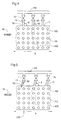
- Fig. 4 is the input end 11 of the turbulence insert, the a perforated plate 100 is closed off from the distribution pipe, shown.
- the perforated plate 100 has arranged in columns and rows Openings 110 for the adjoining turbulence tubes 20, in the present example, these in a column with six superposed turbulence pipes next to each other in series over the entire machine width b are arranged.
- are the feed openings 52 with the adjoining ones Supply lines 13 for the control currents at the upper end of not here shown distribution pipe, with which the plate 100 closes, attached.
- Each supply line 13 is assigned a control valve 15, which in turn is on a common control power supply line 112 through which the Diluent, for example the diluted suspension or also regulated only in the corresponding areas of the water Distribution tube can be supplied.
- 5 are the standard supply lines at an angle ⁇ ⁇ 90 ° to the Horizontal in a plane parallel to the plane of the entry surface of the Stock suspension arranged in the turbulence bundle.
- control currents 50 By injecting the control currents 50 at an angle ⁇ ⁇ 90 ° the control currents a component opposite to the direction of the Suspension stream 40 on. This can deflect the control currents reduced by the suspension flow or completely if ⁇ is correctly selected be avoided. Ideally, there is a broad effect 402 of the Control current, which is limited to a pipe gap.
- To prefer means on the feed lines 13 with which the inclination the same and thus ⁇ can be changed or adjusted.
- the deflection of the flow direction of the Control current is ⁇ 180 °.
Abstract
Description
Die Erfindung betrifft einen Stoffauflauf für eine Papiermaschine gemäß dem
Oberbegriff des Anspruches 1 sowie ein Verfahren zum Einstellen des
Stoffdichte- und Faserorientierungsquerprofils in einem Stoffauflauf gemäß
dem Oberbegriff von Anspruch 10.The invention relates to a headbox for a paper machine according to the
Preamble of
Stoffdichtegeregelte Stoffaufläufe zur Einstellung des Stoffdichte- und Faserorientierungsquerprofils sind aus einer Vielzahl von Anmeldungen bekannt.Material density-controlled headboxes for adjusting the material density and Fiber orientation cross profiles are from a variety of applications known.
Im wesentlichen handelt es sich hierbei um zwei unterschiedliche Konzepte.Essentially, these are two different concepts.
Bei dem ersten Konzept gemäß der US 51 96 091 wird ein Stoffauflauf mit Stoffsuspension über ein sich über die gesamte Maschinenbreite erstreckendes Verteilrohr versorgt. Dieses Verteilrohr ist nicht sektioniert. An das Verteilrohr schließt sich ein maschinenbreiter Turbulenzeinsatz an, der eine Vielzahl von Turbulenzrohren aufweist, die jeweils in Spalten und Reihen regelmäßig angeordnet sind.In the first concept according to US 51 96 091, a headbox is used Stock suspension over the entire machine width extending manifold supplied. This distribution pipe is not sectioned. On the distribution pipe is followed by a machine-wide turbulence insert that has a variety of turbulence tubes, each in columns and rows are arranged regularly.
Zwischen den einzelnen derart regelmäßig angeordneten Turbulenzrohren sind parallel zu diesen Zufuhrleitungen für ein Verdünnungsmittel, das Wasser oder aber auch verdünnte Stoffsuspension sein kann, angeordnet.Between the individual turbulence tubes arranged in such a regular manner are parallel to these feed lines for a diluent, the water or can also be a diluted stock suspension.
Um das Stoffdichtequerprofil über die Maschinenbreite einzustellen, wird je nach dem, welchen Wert die Stoffdichte in dem Turbulenzabschnitt aufweisen soll, Verdünnungsmittel in entsprechender Menge über die Verdünnungsmittelzufuhrleitung in das Verteilrohr eingespeist. Hierbei ist der aus dem Verteilrohr austretende Verdünnungs- bzw. Regelstrom dem in das Turbulenzrohr eintretenden Suspensionsstrom genau entgegengerichtet.In order to adjust the material density cross profile across the machine width, according to the value of the consistency in the turbulence section diluent in an appropriate amount over the Diluent supply line fed into the manifold. Here is the dilution or control flow emerging from the distribution pipe into the Turbulence pipe entering the suspension flow exactly opposite.
Die Verdünnung erfolgt dadurch, daß der Regelstrom durch den langsam entlang der Maschinenbreite strömenden Suspensionsstrom im Verteilrohr um 180° umgelenkt wird und so mit dem eingangsseitig in das Verteilrohr eingespeisten Suspensionsstrom den in den jeweiligen Bereich des Turbulenzeinsatzes eintretenden Suspensionsstrom bildet, der hinsichtlich der Stoffdichte gegenüber dem in das Verteilrohr eingespeisten Suspensionsstrom unter Konstanthaltung des Volumenstroms entsprechend eingestellt wurde.The dilution takes place in that the control current through the slow suspension stream flowing in the distribution pipe along the machine width Is deflected 180 ° and so with the input side into the distribution pipe fed in the suspension stream in the respective area of the Turbulence insert entering suspension stream forms with respect to Material density compared to that fed into the distribution pipe Corresponding suspension flow while keeping the volume flow constant was discontinued.
Nachteilig an Stoffaufläufen gemäß dem ersten Konzept ist, daß aufgrund des nur sehr geringen Durchmessers der Verdünnungsrohre die Austrittsgeschwindigkeit der Verdünnungsmittel bzw. Regelströme in das Verteilrohr sehr hoch ist. Dies bedingt eine relativ große Breitenwirkung eines derartigen Regelstromes, was zur Folge hat, daß die Stoffdichte in den einzelnen Abschnitten des Stoffauflaufes nur sehr grob eingestellt werden kann. Desweiteren erlauben derartig dünne Rohre die Durchführung von nur sehr geringen Dosiermengen, so daß die Bandbreite, in der die Stoffdichte relativ zu der vorgegebenen mittleren Stoffdichte des in das Verteilrohr eintretenden Suspensionsstromes eingestellt werden kann, sehr gering ist.A disadvantage of headboxes according to the first concept is that due to the only very small diameter of the dilution tubes Exit rate of the diluent or control flows into the Distribution pipe is very high. This requires a relatively large broad impact such control current, which has the consequence that the consistency in the individual sections of the headbox can only be set very roughly can. Furthermore, such thin tubes only allow the implementation of very small doses, so the range in which the consistency relative to the specified average consistency of the in the distribution pipe entering suspension flow can be set is very low.
Das andere Konzept eines stoffdichtegeregelten Stoffauflaufes ist prinzipiell in
der DE 40 19 593 offenbart.The other concept of a density-controlled headbox is basically in
Bei dem Konzept gemäß der DE 40 19 593 wird der Suspensionsstrom, der
wieder über ein gemeinsames Verteilrohr zugeführt wird, sektioniert, das heißt
in über die Breite des Stoffauflaufes voneinander unabhängige Teilströme,
sogenannte Sektionsströme, aufgeteilt. Dies kann beispielsweise dadurch
geschehen, daß der Stoffauflauf über seine Breite hinweg durch Trennwände
in Sektionen unterteilt ist.In the concept according to
Eine Einstellung der Stoffdichte erfolgt dann durch Zuführen von
Regelströmen in den einzelnen Sektionen in einen Mischer. An den Mischer
wiederum schließt sich der den einzelnen Sektionen zugeordnete
Turbulenzeinsatz an. Auch bei dem Konzept gemäß der DE 40 19 593 wird
die Stoffdichte der jeweiligen Sektionsströme eingestellt, wobei der
Volumenstrom des Sektionsstromes konstant gehalten wird.The consistency is then adjusted by adding
Control currents in the individual sections in a mixer. To the mixer
again the one assigned to the individual sections closes
Turbulence insert on. Also in the concept according to
Aus der DE 43 23 263 ist für einen sektionierten Stoffauflauf gemäß der
DE 40 19 593 bekannt geworden, daß der Regelstrom unter Winkeln zwischen
5° und 90° gegenüber der Hauptstromrichtung in die einzelnen Sektionen
eingedüst werden kann.DE 43 23 263 is for a sectioned headbox according to the
Desweiteren ist aus der DE 42 39 845 ein Regelverfahren bekannt geworden,
mit dem das Stoffdichte- und Faserorientierungsquerprofil in Abhängigkeit von
der Blattbildung eingestellt werden kann.Furthermore, a control method has become known from
Nachteilig an den Stoffaufläufen gemäß dem zweiten Konzept ist, daß die Einstellung eines Stoffdichte- und Faserorientierungsquerprofils immer voraussetzt, daß der zugeführte Suspensionsstrom in Teilströme aufgeteilt wird, um in einem sich daran anschließenden Mischer für die einzelnen Sektionen entsprechend eingestellt zu werden.A disadvantage of the headboxes according to the second concept is that the Always set a material density and fiber orientation cross profile assumes that the supplied suspension stream is divided into partial streams is going to be in a subsequent mixer for the individual Sections to be adjusted accordingly.
Dies hat einen hohen konstruktiven Aufwand zur Folge. Desweiteren ist der Platzbedarf einer solchen Anordnung erheblich.This results in a high level of design effort. Furthermore, the Space requirement of such an arrangement significantly.
Aufgabe der Erfindung ist es daher, einen Stoffauflauf anzubieten, bei dem die Nachteile der Anordnungen gemäß dem Stand der Technik vermieden werden. The object of the invention is therefore to offer a headbox in which the disadvantages of the arrangements according to the prior art avoided will.
Es soll ein Stoffauflauf geschaffen werden, bei dem ohne eine Sektionierung des in den Stoffauflauf eingeführten Suspensionsstromes eine ausreichend scharfe Regelung des Stoffdichtequerprofiles ermöglicht wird. Insbesondere soll die Breitenwirkung gegenüber der aus der US 5196091 bekannten Vorrichtung verbessert, das heißt minimiert werden. Neben der Vorrichtung soll die Erfindung auch ein Verfahren zur Verfügung stellen, mit dem eine Einstellung des Stoffdichte- und Flächengewichtsquerprofils möglich ist, wobei eine Sektionierung der Teilströme vermieden wird und trotzdem noch eine ausreichend geringe Breitenwirkung eingehalten wird.A headbox is to be created in which without a sectioning of the suspension stream introduced into the headbox is sufficient sharp regulation of the material density cross profile is made possible. Especially the width effect compared to that known from US 5196091 Device improved, that is, minimized. In addition to the device the invention is also intended to provide a method with which a Adjustment of the fabric density and basis weight cross profile is possible, whereby a division of the partial streams is avoided and still one sufficiently low broad impact is observed.
Erfindungsgemaß wird diese Aufgabe durch den Stoffauflauf in Anspruch 1
und das Verfahren gemäß Anspruch 10 gelöst.According to the invention, this object is achieved by the headbox in
Erfindungsgemäß ist vorgesehen, daß die Vielzahl von Zufuhrleitungen für die Regelströme wie bei der US 5196091 direkt in das maschinenbreite Verteilrohr münden. Die Zufuhrleitungen sind unmittelbar vor dem einströmseitigen Ende des Turbulenzeinsatzes angeordnet, wobei der Suspensionsstrom in diesem Bereich nur noch eine Strömungskomponente in Richtung des Turbulenzeinsatzes aufweist. In der Regel sind die einzelnen Zufuhrleitungen in einer Reihe in Richtung der Maschinenbreite angeordnet. Als Winkel, unter dem die Zufuhrleitung für den Regelstrom in das Verteilrohr eingeführt wird, sind Winkel zwischen 5° und 170° in Bezug auf die Strömungsrichtung des Suspensionsstromes im Turbulenzeinsatz möglich, bevorzugt wird aber unter einem rechten Winkel eingedüst.According to the invention it is provided that the plurality of supply lines for the Control currents as in US 5196091 directly into the machine-wide distribution pipe flow out. The supply lines are immediately before the upstream end arranged of the turbulence insert, the suspension flow in this Only one flow component in the direction of the Has turbulence insert. As a rule, the individual supply lines arranged in a row in the direction of the machine width. As an angle, under which the supply line for the control current is introduced into the distribution pipe, are angles between 5 ° and 170 ° with respect to the flow direction of the Suspension flow possible in turbulence, but is preferred under injected at a right angle.
Auch bei dem erfindungsgemäßen Verfahren wird dafür Sorge getragen, daß die Regelströme direkt vor Eintritt des Suspensionsstromes in den Turbulenzeinsatz vorzugsweise unter einem rechten Winkel zugeführt werden. Besonders bevorzugt ist es, wenn die Regelstromgeschwindigkeit so gewählt wird, daß auch noch am weitesten von der Zufuhröffnung entfernten Turbulenzrohr des Turbulenzeinsatzes eine Strömungskomponente in Richtung der Eindüsung und quer zur Richtung der Suspensionsströmung vorliegt.Care is also taken in the method according to the invention that the control currents directly before the suspension stream enters the Turbulence insert are preferably fed at a right angle. It is particularly preferred if the control current speed is selected in this way will be the most distant from the feed opening Turbulence tube of the turbulence insert a flow component in Direction of the injection and transverse to the direction of the suspension flow is present.
Die Erfindung soll nachfolgend anhand der Zeichnungen beispielhaft beschrieben werden.The invention is intended to serve as an example with reference to the drawings to be discribed.
Es zeigen:
- Fig. 1:
- eine Schnittansicht durch einen erfindungsgemäßen Stoffauflauf in Maschinenlängsrichtung;
- Fig. 2:
- eine vergrößerte Darstellung des Bereiches, in dem die Regelströme dem Suspensionsstrom zugemischt werden;
- Fig. 3:
- eine Draufsicht auf einen erfindungsgemäßen Stoffauflauf nach Fig. 1 in Maschinenlängsrichtung;
- Fig. 4 und Fig. 5:
- einen Ausschnitt einer Draufsicht auf den eingangsseitigen Teil des Turbulenzabschnittes mit den Zufuhrleitungen für die Regelströme im maschinenbreiten Verteilrohr;
- Fig. 6:
- dieselbe Ansicht wie Fig. 4 oder 5, gemäß dem Stand der Technik, wie aus der US 5196091 bekannt.
- Fig. 1:
- a sectional view through a headbox according to the invention in the machine longitudinal direction;
- Fig. 2:
- an enlarged view of the area in which the control flows are mixed with the suspension flow;
- Fig. 3:
- a plan view of a headbox according to the invention of Figure 1 in the machine longitudinal direction.
- 4 and 5:
- a detail of a plan view of the inlet-side part of the turbulence section with the supply lines for the control currents in the machine-wide distribution pipe;
- Fig. 6:
- the same view as Fig. 4 or 5, according to the prior art, as known from US 5196091.
In Fig. 1 ist ein Längsschnitt durch einen Stoffauflauf gemäß der Erfindung dargestellt.In Fig. 1 is a longitudinal section through a headbox according to the invention shown.
Die Stoffsuspension wird über ein Verteilrohr 1, entlang der Maschinenbreite
zur Verfügung gestellt. Dabei weist das Verteilrohr einströmseitig einen
größeren Durchmesser 3 als ausströmseitig 5 auf. Das Verteilrohr 1 ist direkt
an den Turbulenzeinsatz 7 angeschlossen. Im Anschlußbereich 9 des
Verteilrohres an das eingangsströmseitige Ende 11 des Turbulenzeinsatzes 7
sind die Zufuhrleitungen 13 für die Regelströme, sogenannte
Regelstromzufuhrleitungen, vorgesehen. Um den Regelstrom, der über die
Leitungen 13 dem in den Turbulenzeinsatz strömenden Suspensionsstrom
zugeführt wird, einstellen zu können, sind in der Zufuhrleitung Regelventile 15
vorgesehen, die durch eine entsprechende Steuerung bzw. Regelung, wie aus
der DE 42 39 845, deren Offenbarungsgehalt vollumfänglich in die Anmeldung
miteinbezogen wird, bekannt angesteuert werden können. Eine derartige
Regelung ist in vorliegendem Ausführungsbeispiel nicht dargestellt. Der
Turbulenzeinsatz 7 umfaßt in einer Ausführungsform eine Vielzahl von
Turbulenzrohren 20, wobei über die Höhe h des Turbulenzeinsatzes eine
Vielzahl von Turbulenzrohren 201, 202, 203, 204, 205 in einer Spalte 200
angeordnet sein können.The stock suspension is fed over a
Am ausgangsseiten Ende 30 des Turbulenzeinsatzes sind verstellbare
Blenden 32, 34 vorgesehen, aus denen der Stoffstrahl durch eine
Austrittsöffnung 36 ausströmt.At the outlet end 30 of the turbulence insert are
In Fig. 2 ist in einer vergrößerten Darstellung nochmals der eingangsseitige
Bereich des erfindungsgemäßen Stoffauflaufes gemäß Fig. 1 mit den dort
herrschenden Strömungsverhältnissen im Schnitt dargestellt. Durch das
Verteilrohr 1 wird die Suspension aus der Papierebene der Zeichnung wie
durch den Pfeil 40 dargestellt in Richtung der Maschinenbreite zugeführt. Im
Verteilrohr selbst findet eine Umlenkung der Suspensionsströmung gemäß
Pfeil 40 in Maschinenlängsrichtung, das heißt auf das eingangsseitige
Ende 11 des Turbulenzeinsatzes 7 hin, statt. Es resultiert im Anschlußbereich
des Verteilrohres 9 ein Strömungsverhalten wie durch Pfeil 42 dargestellt, d.h.
in Richtung des Turbulenzeinsatzes.In Fig. 2 is an enlarged view again the input side
Area of the headbox according to the invention shown in FIG. 1 with the there
prevailing flow conditions shown in section. By the
Über die Zufuhrleitung 13 wird ein Regelstrom 50 in den Anschlußbereich 9
des Verteilrohres unter einem Winkel α, der vorliegend 90° beträgt,
eingespeist. Der Regelstrom 50 weist eine ausreichend hohe Geschwindigkeit
auf, so daß auch am der Zuführöffnung 52 gegenüberliegenden Ende des
Verteilrohres, das heißt also im Abstand h von der Zufuhröffnung entfernt, der
Regelstrom eine Konponente senkrecht zur Richtung der
Suspensionsströmung 42 aufweist. Zur Einstellung der Stoffdichte dient aber
alleine die am einströmseitigen Ende 11 des Turbulenzeinsatzes vorhandene
Komponente des Regelstromes parallel zur Richtung der
Suspensionsströmung 42. Das heißt der Regelstrom muß zur Einstellung der
Stoffdichte umgelenkt werden. Im Gegensatz zur US 5196091 aber ist es nicht
erforderlich den Regelstrom um 180° umzulenken, damit dieser eine
Komponente parallel zum Suspensionsstrom 42 aufweist. Eine Umlenkung
entsprechend dem Eindüswinkel α um einen Winkel der stets < 180° ist, ist
hierfür ausreichend. Selbstverständlich kann der Stoffauflauf Mittel an einer
oder allen Zufuhrleitungen 13 zur variablen Einstellung von α umfassen.A control current 50 is fed into the
Eine Umlenkung < 180° der Strömungsrichtung weist eine Reihe von
Vorteilen gegenüber der Eindüsung gemäß der US 5196091 auf. Zum ersten
kann die Größe der Zufuhröffnung beliebig gewählt werden und ist nicht
durch die der umgebenden Turbulenzrohr wie in der oben genannten US-Patentschrift
begrenzt. Eine größere Zufuhröffnung erlaubt aber die Eindüsung
der Regelströme mit einer geringeren Geschwindigkeit und höherer
Konsistenz, so daß sich eine größere Variationsbreite Δ ρ0 für die
Einstellbarkeit der Stoffdichte um einen mittleren, zugeführten
Stoffdichtewert ρ0 vergrößert. Dies erlaubt, daß die Stoffdichte über die Breite
des Stoffauflaufes wenigstens in einem Bereich
Ein weiterer Vorteil ist darin zu sehen, daß aufgrund der niedrigen Eindüsgeschwindigkeit und einer Umlenkung des Regelstromes, der kleiner als 180° ist, die Breitenwirkung des eingedüsten Regelstromes geringer ist als im Falle der oben erwähnten US 5196091. Dies wiederum hat zum Vorteil, daß die Stoffdichte in dem gewünschten Bereich relativ scharf begrenzt exakt eingestellt werden kann, ohne daß es zu Überlappungen in der Regelwirkung in benachbarten Bereichen kommt, die nur sehr schwer beeinflußt werden können.Another advantage is that due to the low Injection speed and a deflection of the control current, the smaller than 180 °, the width effect of the injected control current is less than in the case of the above-mentioned US 5196091. This in turn has the advantage that the fabric density in the desired area is relatively sharply limited exactly can be set without overlapping the control effect comes in neighboring areas that are very difficult to influence can.
Fig. 3 zeigt eine Draufsicht auf einen Stoffauflauf gemäß Fig. 1, wobei aber
nur ein Teil der gesamten Maschinenbreite b dargestellt ist. Wie bereits in der
Schnittansicht von Fig. 1 angedeutet, ist das Verteilrohr 1, das sich über die
gesamte Maschinenbreite b erstreckt, zulaufend vom einströmseitigen zum
ausströmseitigen Ende hin ausgebildet, das heißt daß der Querschnitt 3 am
Eintrittsende größer als der Querschnitt 5 am Austrittsende 60 ist. Am
austrittsseitigen Ende befindet sich ein Auslaßstutzen 62, durch den der Anteil
des zugeführten Suspensionsstroms, der nicht wie mit Pfeil 40 angedeutet in
Richtung des Turbulenzeinsatzes umgelenkt wird, abgeführt werden kann. Um
die Umlenkung des Suspensionsstromes 40 im Verteilrohr 1 direkt vor dem
Turbulenzeinsatz 7 in Richtung des Turbulenzeinsatzes zu unterstützen,
können im Verteilrohr 1 verstellbare Führungswände 300 angeordnet sein. Es
ist möglich, die Führungswände 300 gebogen auszuführen, so daß keine
Staupunkte im Suspensionsstrom auftreten. Die Eintrittsöffnungen 52 der
Zufuhrrohre für die Regelströme aus Verdünnungsmittel in das Verteilrohr sind
über die Maschinenbreite b des Stoffauflaufes in einer Reihe unmittelbar vor
dem Turbulenzeinsatz 7 angeordnet. Der Turbulenzeinsatz 7 umfaßt
nebeneinanderliegende, das heißt in einer Reihe angeordnete Rohrbündel
bzw. Rohrspalten von Turbulenzrohren 20. In vorliegendem
Ausführungsbeispiel sind in der geschnittenen Ansicht insgesamt fünf
nebeneinanderliegende Turbulenzrohre 2000, 2001, 2002, 2003 und 2004
gezeigt. An den Turbulenzeinsatz 7 schließt sich eine über die
Maschinenbreite verstellbare Blende 32 an.FIG. 3 shows a top view of a headbox according to FIG. 1, however
only part of the total machine width b is shown. As already in the
1 indicated, is the
In Fig. 4 ist das eingangsseitige Ende 11 des Turbulenzeinsatzes, der mit
einer Lochplatte 100 gegenüber dem Verteilrohr abgeschlossen ist,
dargestellt. Die Lochplatte 100 weist in Spalten und Reihen angeordnete
Öffnungen 110 für die sich daran anschließenden Turbulenzrohre 20 auf,
wobei in vorliegendem Beispiel diese in einer Spalte mit sechs
übereinanderliegenden Turbulenzrohren nebeneinander in Reihe über die
gesamte Maschinenbreite b angeordnet sind. Wie aus Fig. 4 zu entnehmen,
sind die Zufuhröffnungen 52 mit den daran anschließenden
Zufuhrleitungen 13 für die Regelströme am oberen Ende des hier nicht
dargestellten Verteilrohres, mit dem die Platte 100 abschließt, angebracht.
Jeder Zufuhrleitung 13 ist ein Regelventil 15 zugeordnet, die wiederum an
eine gemeinsame Regelstromzufuhrleitung 112, über die das
Verdünnungsmittel, beispielsweise die verdünnte Stoffsuspension oder aber
auch lediglich Wasser geregelt in die entsprechenden Bereiche des
Verteilrohres zugeführt werden kann.In Fig. 4 is the
Gemäß Fig. 4 die Regelstromzufuhrleitungen 13 direkt über einer
Turbulenzrohrspalte unter einem Winkel γ gegenüber der Horizontalen in einer
Ebene parallel zur dargestellten Ebene der Eintrittsfläche der Stoffsuspension
in das Turbulenzrohrbündel angeordnet. Der Winkel γ ist in der
Ausführungsform gemäß Fig. 4 ein rechter, also γ = 90°. Bei geringer
Eindüsgeschwindigkeit wird sich die Breitenwirkung der jeweiligen
Regelströme nur auf diese und maximal die benachbarte Rohrspalte
beschränken, so daß eine sehr genaue abschnittsweise Einstellung der
Stoffdichte über die Maschinenbreite b möglich ist. Überlappungen bzw.
Störungen sind so weitgehend ausgeschlossen. Eine beispielhafte
Breitenwirkung eines durch eine Öffnung 52 eingespeisten Regelstrome 50
bei einem Hauptsuspensionsstrom 40, der von links her eingedüst wird, ist
durch die Regelstromwolke 400 angedeutet. Wie hieraus zu entnehmen, wird
der Regelstrom 50 je weiter er von der Öffnung 52 entfernt ist, umso mehr in
Richtung des Suspensionsstromes 40 abgelenkt und kann somit auch eine
beanchbarte Rohrspalte erfassen.4, the control
Dies wird bei einer Ausführungsform gemäß Fig. 5 vermieden. Gemäß Fig. 5 sind die Regelzufuhrleitungen unter einem Winkel γ < 90° gegenüber der Horizontalen in einer Ebene parallel zur Ebene der Eintrittsfläche der Stoffsuspension in das Turbulenzbündel angeordnet.This is avoided in an embodiment according to FIG. 5. 5 are the standard supply lines at an angle γ <90 ° to the Horizontal in a plane parallel to the plane of the entry surface of the Stock suspension arranged in the turbulence bundle.
Durch das Eindüsen der Regelströme 50 unter dem Winkel γ < 90°, weisen
die Regelströme eine Komponente entgegengesetzt zur Richtung des
Suspensionsstromes 40 auf. Hierdurch kann eine Ablenkung der Regelströme
durch den Suspensionsstrom verringert bzw. bei richtiger Wahl von γ völlig
vermieden werden. Idealerweise ergibt sich eine Breitenwirkung 402 des
Regelstromes, der auf eine Rohrspalte beschränkt ist.By injecting the
In einer besonders bevorzugten Ausführungsform kann vorgesehen sein,
Mittel an den Zufuhrleitungen 13 vorzuziehen, mit denen die Neigung
derselben und damit γ verändert bzw. eingestellt werden kann.In a particularly preferred embodiment it can be provided that
To prefer means on the
Die Eindüsung gemäß dem Stand der Technik in Form der US 51 96 091 ist
in Fig. 5 dargestellt. Wiederum ist dies eine Ansicht der mit Löchern 110
versehenen Abschlußplatte 100 des Turbulenzeinsatzes des sich über die
Maschinenbreite erstreckenden Verteilrohres. Im Gegensatz zu der
erfindungsgemäßen Anordnung sind die Regelstromzufuhrleitungen parallel zu
den Turbulenzrohren angeordnet und die Eintrittsöffnungen 52 für die
Zufuhrleitungen sind benachbart zu den Öffnungen 110 der Turbulenzrohre.
Hierdurch ist die Größe der Eintrittsöffnungen auf den Abstand zwischen zwei
Spalten von Turbulenzrohren beschränkt, wohingegen die Eintrittsöffnungen
gemäß Fig. 4 auch wesentlich größer als in der dargestellten Abbildung
ausgeführt sein können. Weiterer Nachteil der Anordnung gemäß dem Stand
der Technik wie in Fig. 5 dargestellt ist, daß wenigstens eine 180° Umlenkung
des Regelstromes erfolgen muß, wenn mit Hilfe von diesem die Stoffdichte in
den zugeführten Suspensionsstrom geregelt werden soll.The injection according to the prior art in the form of US 51 96 091
shown in Fig. 5. Again, this is a view of the one with
Mit der erfindungsgemäßen Vorrichtung und dem erfindungsgemäßen Verfahren ist es dagegen erstmals möglich, in einer kompakten Bauweise eine sehr exakte Stoffdichte- und Faserorientierungsquerprofileinstellung in einem Stoffauflauf zu erzielen, wobei die Umlenkung der Strömungsrichtung des Regelstromes < 180° ist.With the device according to the invention and the inventive On the other hand, it is now possible for the first time to use a compact design very exact fabric density and fiber orientation cross profile adjustment in one To achieve headbox, the deflection of the flow direction of the Control current is <180 °.
Claims (13)
das Verfahren ist dadurch gekennzeichnet, daß
the method is characterized in that
Applications Claiming Priority (2)
| Application Number | Priority Date | Filing Date | Title |
|---|---|---|---|
| DE19634993 | 1996-08-30 | ||
| DE19634993A DE19634993A1 (en) | 1996-08-30 | 1996-08-30 | Method and device for adjusting the stock density and fiber orientation profile in a headbox |
Publications (2)
| Publication Number | Publication Date |
|---|---|
| EP0826818A2 true EP0826818A2 (en) | 1998-03-04 |
| EP0826818A3 EP0826818A3 (en) | 1998-04-01 |
Family
ID=7804064
Family Applications (1)
| Application Number | Title | Priority Date | Filing Date |
|---|---|---|---|
| EP97111794A Withdrawn EP0826818A3 (en) | 1996-08-30 | 1997-07-11 | Process and apparatus for adjusting the consistency and fibre orientation profile in a headbox |
Country Status (4)
| Country | Link |
|---|---|
| US (1) | US6136152A (en) |
| EP (1) | EP0826818A3 (en) |
| CN (1) | CN1175644A (en) |
| DE (1) | DE19634993A1 (en) |
Families Citing this family (6)
| Publication number | Priority date | Publication date | Assignee | Title |
|---|---|---|---|---|
| DE19908898A1 (en) * | 1999-03-02 | 2000-09-07 | Voith Sulzer Papiertech Patent | Process for metering a fluid medium into a suspension stream of a headbox and headbox |
| FI105407B (en) * | 1999-05-27 | 2000-08-15 | Valmet Corp | Inlet box in a papermaking machine or cardboard making machine |
| AU2003291285A1 (en) * | 2002-11-01 | 2004-06-03 | International Paper Company | Method of making a stratified paper |
| AU2005326567B2 (en) * | 2005-02-03 | 2010-12-09 | Pmt Italia S.P.A. | Apparatus and method for controlling the consistency of a flow of stock solution in a papermaking machine |
| CN102154914B (en) * | 2011-02-24 | 2013-03-20 | 钟洲 | Method for preparing aramid paper and aramid paper prepared by method |
| EP3088604B1 (en) * | 2015-04-28 | 2020-03-25 | Valmet Technologies Oy | Method and system for the optimization of properties of a multilayer fiber web in fiber web manufacture |
Citations (3)
| Publication number | Priority date | Publication date | Assignee | Title |
|---|---|---|---|---|
| US3002558A (en) * | 1957-12-21 | 1961-10-03 | Voith Gmbh J M | Flow distributor for fiber material for use in connection with paper making machines |
| US3328236A (en) * | 1964-06-22 | 1967-06-27 | Black Clawson Co | Bunched tube approach to a headbox of a papermaking machine |
| DE4323263A1 (en) * | 1993-07-12 | 1994-01-13 | Voith Gmbh J M | Stock inlet for paper-making machine - has flow-controlled jet feeds across main flow channel section with main flows and turbulence zone, allowing cross=sectional adjustment, etc. |
Family Cites Families (7)
| Publication number | Priority date | Publication date | Assignee | Title |
|---|---|---|---|---|
| US4469556A (en) * | 1982-09-29 | 1984-09-04 | Beloit Corporation | Flow distributor |
| DE3741603A1 (en) * | 1987-12-09 | 1989-06-22 | Voith Gmbh J M | FABRIC DRAIN FOR A PAPER MACHINE OR THE LIKE. |
| US5196091A (en) * | 1991-10-29 | 1993-03-23 | Beloit Technologies, Inc. | Headbox apparatus with stock dilution conduits for basis weight control |
| DE4140657C2 (en) * | 1991-12-10 | 1994-07-14 | Voith Gmbh J M | Headbox |
| DE4416909C2 (en) * | 1994-05-13 | 1997-12-11 | Voith Sulzer Papiermasch Gmbh | Headbox for a paper machine |
| DE4437180C2 (en) * | 1994-10-18 | 1997-03-20 | Voith Sulzer Papiermasch Gmbh | Process for producing a headbox and intermediate part of a headbox of a paper or board machine |
| US5626722A (en) * | 1995-06-01 | 1997-05-06 | Valmet Corporation | Headbox of a paper/board machine |
-
1996
- 1996-08-30 DE DE19634993A patent/DE19634993A1/en not_active Withdrawn
-
1997
- 1997-07-11 EP EP97111794A patent/EP0826818A3/en not_active Withdrawn
- 1997-08-13 CN CN97117360A patent/CN1175644A/en active Pending
- 1997-08-29 US US08/921,022 patent/US6136152A/en not_active Expired - Fee Related
Patent Citations (3)
| Publication number | Priority date | Publication date | Assignee | Title |
|---|---|---|---|---|
| US3002558A (en) * | 1957-12-21 | 1961-10-03 | Voith Gmbh J M | Flow distributor for fiber material for use in connection with paper making machines |
| US3328236A (en) * | 1964-06-22 | 1967-06-27 | Black Clawson Co | Bunched tube approach to a headbox of a papermaking machine |
| DE4323263A1 (en) * | 1993-07-12 | 1994-01-13 | Voith Gmbh J M | Stock inlet for paper-making machine - has flow-controlled jet feeds across main flow channel section with main flows and turbulence zone, allowing cross=sectional adjustment, etc. |
Also Published As
| Publication number | Publication date |
|---|---|
| CN1175644A (en) | 1998-03-11 |
| DE19634993A1 (en) | 1998-03-05 |
| US6136152A (en) | 2000-10-24 |
| EP0826818A3 (en) | 1998-04-01 |
Similar Documents
| Publication | Publication Date | Title |
|---|---|---|
| DE4323263C2 (en) | Process for the sectional influencing of the stock density and the fiber orientation in a headbox of a paper machine and headbox for carrying out the process | |
| DE3741603C2 (en) | ||
| DE1761229C3 (en) | Headbox for paper machines | |
| EP2379803B1 (en) | Headbox for a machine for producing a fibrous web | |
| EP2379800B1 (en) | Headbox for a machine for producing a fibrous web | |
| EP0629739B2 (en) | Headbox for a paper machine | |
| WO2010069651A1 (en) | Headbox for a machine for producing a fibrous web | |
| DE102008054899A1 (en) | Headbox for a machine for producing a fibrous web | |
| WO2010145871A2 (en) | Headbox for a machine for producing a fibrous material web | |
| WO2011006691A1 (en) | Headbox for a machine for producing a fibrous web | |
| DE102008054894A1 (en) | Headbox for a machine for producing a fibrous web | |
| DE4416899C2 (en) | Process for the local admixing of fluid into a headbox and device for its execution | |
| EP1619298A2 (en) | Headbox of a machine for manufacturing a fibrous web, in particular a papier or board web | |
| EP0826818A2 (en) | Process and apparatus for adjusting the consistency and fibre orientation profile in a headbox | |
| DE1511218B2 (en) | PAPER MASH FEEDING DEVICE FOR PAPER MACHINES | |
| DE2800547B2 (en) | Headbox for paper machines | |
| EP2487292A1 (en) | Head-box for a machine for producing a sheet of fibrous material | |
| DE4422907C2 (en) | Sectional feed of the headbox of a paper machine | |
| DE4140657C2 (en) | Headbox | |
| DE4433445C1 (en) | Headbox of a paper machine | |
| DE102018120162A1 (en) | HEADBOX | |
| DE4336997C2 (en) | Transition piece between distributor and forming chamber of the headbox of a paper machine | |
| DE2023139C3 (en) | Device for the production of fiber fleece | |
| DE4310223A1 (en) | Turbulence generator for a flow box of a paper machine | |
| DE2041108C3 (en) | Headbox for paper machines |
Legal Events
| Date | Code | Title | Description |
|---|---|---|---|
| PUAI | Public reference made under article 153(3) epc to a published international application that has entered the european phase |
Free format text: ORIGINAL CODE: 0009012 |
|
| PUAL | Search report despatched |
Free format text: ORIGINAL CODE: 0009013 |
|
| AK | Designated contracting states |
Kind code of ref document: A2 Designated state(s): AT BE CH DE FI LI SE |
|
| AX | Request for extension of the european patent |
Free format text: AL;LT;LV;RO;SI |
|
| AK | Designated contracting states |
Kind code of ref document: A3 Designated state(s): AT BE CH DE DK ES FI FR GB GR IE IT LI LU MC NL PT SE |
|
| AX | Request for extension of the european patent |
Free format text: AL;LT;LV;RO;SI |
|
| 17P | Request for examination filed |
Effective date: 19981001 |
|
| AKX | Designation fees paid |
Free format text: AT BE CH DE FI LI SE |
|
| RBV | Designated contracting states (corrected) |
Designated state(s): AT BE CH DE FI LI SE |
|
| RAP1 | Party data changed (applicant data changed or rights of an application transferred) |
Owner name: VOITH SULZER PAPIERTECHNIK PATENT GMBH |
|
| 17Q | First examination report despatched |
Effective date: 20010306 |
|
| STAA | Information on the status of an ep patent application or granted ep patent |
Free format text: STATUS: THE APPLICATION HAS BEEN WITHDRAWN |
|
| 18W | Application withdrawn |
Withdrawal date: 20010309 |