EP0826534B1 - Pare-soleil pour véhicules - Google Patents
Pare-soleil pour véhicules Download PDFInfo
- Publication number
- EP0826534B1 EP0826534B1 EP97113608A EP97113608A EP0826534B1 EP 0826534 B1 EP0826534 B1 EP 0826534B1 EP 97113608 A EP97113608 A EP 97113608A EP 97113608 A EP97113608 A EP 97113608A EP 0826534 B1 EP0826534 B1 EP 0826534B1
- Authority
- EP
- European Patent Office
- Prior art keywords
- sun visor
- trough
- shaped depression
- visor body
- bearing housing
- Prior art date
- Legal status (The legal status is an assumption and is not a legal conclusion. Google has not performed a legal analysis and makes no representation as to the accuracy of the status listed.)
- Expired - Lifetime
Links
Images


Classifications
-
- B—PERFORMING OPERATIONS; TRANSPORTING
- B60—VEHICLES IN GENERAL
- B60J—WINDOWS, WINDSCREENS, NON-FIXED ROOFS, DOORS, OR SIMILAR DEVICES FOR VEHICLES; REMOVABLE EXTERNAL PROTECTIVE COVERINGS SPECIALLY ADAPTED FOR VEHICLES
- B60J3/00—Antiglare equipment associated with windows or windscreens; Sun visors for vehicles
- B60J3/02—Antiglare equipment associated with windows or windscreens; Sun visors for vehicles adjustable in position
- B60J3/0204—Sun visors
- B60J3/0278—Sun visors structure of the body
- B60J3/0282—Sun visors structure of the body specially adapted for a courtesy mirror
Definitions
- the invention relates to a sun visor for vehicles with a hollow, shaped as a blow molded sun visor body, the one approximately has a rectangular shape and an embedded in a corner area
- EP 0 562 085 B1 shows a sun visor for motor vehicles that has a hollow sun visor body designed as a blow molded body. There is one in a corner area of the sun visor body Retaining spring for receiving a section of a sun visor axis. In a Broad side of the sun visor body is a trough-shaped Well for receiving a mirror. The sun visor body is from surrounded by an envelope-like outer cover.
- the known sun visor has high mechanical strength
- a variety of reinforcing ribs provided on the inside of the sun visor body are facing and punched from the outside of the sun visor body are made here, each rib being hollow and on the outer surface of the corresponding side of the sun visor body defines a small hole. The visible openings formed by the ribs on the sun visor body through the cover covered.
- the present invention is based on the object, the manufacture a sun visor of the type mentioned to simplify and in particular Take precautions to ensure that the sun visor body is no longer must necessarily be covered with a covering material.
- the invention provides that the side walls the trough-shaped depression with a step-shaped Paragraph formed all-round support flange are designed that the stiffening beads arranged only in the bottom of the trough-shaped depression are, namely as diagonally running, crossing stiffening ribs, which are located on the inner wall of the adjacent broadside of the Support the sun visor body and that in the bottom of the trough-shaped Deepening holes for receiving fastening elements of the supplementary component are located.
- a sun visor body of the invention Sun visor a smooth, uninterrupted surface on, so that the reason, especially when using any colored Plastic films on a covering of the sun visor body with covering material can be dispensed with.
- the sun visor body also be wrapped in conventionally if so is desired by the customer base.
- the stiffening beads are integral with the inner wall of the neighboring ones Broad side of the sun visor body connected. This can be done in the simplest Way through the heat of deformation when blow molding the sun visor body be achieved.
- a further development of the invention provides that a side wall of the trough-shaped Recess has an opening zone and that between this zone and the bearing bore of the bearing housing a through channel extends for the passage of electrical supply lines. This configuration is particularly important if a mirror assembly equipped with an electric lighting device be inserted into the trough-shaped recess of the sun visor body should.
- the passage channel expediently consists of a tubular one Approach to the bearing housing.
- an additional component comes with an electrical one Illumination device equipped mirror assembly a cover as well as a mirror framed by a frame.
- the cover, the frame or the mirror unit can be on the back arranged, e.g. B. harpoon-shaped anchoring elements be equipped so that an arrangement of the respective supplementary component in the trough-shaped recess through a particularly quick and easy feasible plug-in assembly can take place.
- Another embodiment of the invention provides that for the bracket of the supplementary component, an adapter frame with top and bottom fastening elements is used. This has the particular advantage that Existing standard components for the assembly of the new sun visor body can be used.
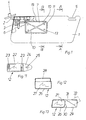
- the sun visor consists of a sun visor body 1, a sun visor axis 2, which has an end region in a in the sun visor body 1 stored bearing housing 3 engages and with the other end of a bearing block 4 is received and from a counter bearing block (not shown) for the detachable mounting of one on the sun visor body 1 trained counter bearing pin 5.
- the sun visor body 1 is designed as a hollow blow molded body, wherein the counter bearing pin 5 is a one-piece and material-uniform component of the sun visor body 1 forms.
- the bearing housing 3 is embedded, specifically within the cavity 6, whereby anchoring is also to be understood as embedded.
- the sun visor body 1 has a trough-shaped shape on a broad side Indentation 7 with a bottom 8 and with peripheral side walls 9.
- the bottom 8 there are two diagonally running stiffening beads which intersect in the middle 10 formed on the inner wall of the adjacent At least support broadside.
- a cohesive connection is preferred provided by the heat of molding during blow molding of the sun visor body 1 results without special assistance.
- the bottom 8 of the trough-shaped recess 7 there are also holes 13.
- the bottom 8 is spaced from the adjacent broad side of the sun visor body 1.
- the side walls 9 of the trough-shaped recess 7 are through a stepped shoulder formed circumferential support flange 11 executed. This creates an additional stiffening of the sun visor body 1 achieved and a edition for an additional component to be explained 12 created.
- a side wall 9 of the trough-shaped recess 7 has one that can be opened Zone 14 and between this zone 14 and the bearing bore of the bearing housing 3 extends a through channel for performing electrical Supply lines, the through-channel consisting of a tubular Approach 15 on the bearing housing 3.
- the zone to be opened can be created according to FIGS. 7 and 8 by that a pocket-like depression 16 'is locally formed in the bottom 8. by virtue of A dimensional specification in the mold of the blow mold creates one thin swimming skin 16 that can be easily pierced.
- the zone 14 to be opened can also be created as a result according to FIGS. 9 and 10 be that a calotte 17 is locally formed in the bottom 8, the has a material thinner 18 on its circumference.
- a free cut 19 is created in the zone 14 to be opened, whereby the cap 17 can be pushed through and due to the dead center effect the original outward curvature now permanently inward is.
- the trough-shaped recess 7 is used due to the training described for the technical stiffening of the sun visor body 1 and, as also mentioned, a supplementary component 12 take.
- FIG. 6 there is the supplementary component 12 from a closure cover 20 covering the recess 7, which is supported with its peripheral edge on the support flange 11 and via harpoon-like locking elements 21, which holes 13 enforce, is held.
- the cover 20 can the sun visor body 1 be color-matched or a complementary color as well have, like a company logo or whatever decoration, so that the cover 20 easily for good looks of the Sun visor can contribute.
- FIG. 11 shows a supplementary component designed as a mirror assembly 22 12, with lenses 23 making it clear that this mirror assembly 22 with an electric lighting device, the training of State of the art is heard, equipped.
- a housing extension 24 On a housing extension 24 a company logo 25 is attached.
- FIG. 12 shows, as a supplementary component 12, one enclosed by a frame 26 Mirror 27, on the frame 26 a hinged lid 28 to cover the Mirror 27 is articulated.
- FIG. 13 shows a supplementary component 12 with a frame 26 enclosed Mirror 27, with an extension 29 arranged on the frame 26 is.
- the extension 29 takes a slide cover 30 for the mirror 27 on and can in a sloping opening slot 31 a parking ticket 32 or the like. Record.
- the adapter frame 33 has locking elements formed on the underside 21, which are matched to the hole pattern in the bottom 8, as well as on the top molded locking elements 26 on the mounting holes in the frame 26 are matched. In this case it is assumed that it is in the supplementary component 12 by a conventional sun visor standard component used.
Landscapes
- Engineering & Computer Science (AREA)
- Mechanical Engineering (AREA)
- Blow-Moulding Or Thermoforming Of Plastics Or The Like (AREA)
- Photovoltaic Devices (AREA)
- Vehicle Step Arrangements And Article Storage (AREA)
- Arrangements Of Lighting Devices For Vehicle Interiors, Mounting And Supporting Thereof, Circuits Therefore (AREA)
Claims (7)
- Pare-soleil pour véhicules, comprenant un corps de pare-soleil (1) réalisé en tant que corps creux moulé par soufflage, qui présente une forme approximativement rectangulaire et qui porte, dans une partie de coin, un logement de palier intégré (3) avec un alésage de palier pour le support à une extrémité d'un axe de pare-soleil (2) reçu à l'autre extrémité par un coussinet (4), lequel axe de pare-soleil est serré par un ressort d'encliquetage (34) reçu par le logement de palier (3), lequel ressort présente en outre, au niveau de la partie d'extrémité opposée au logement de palier (3) une tige conjuguée (5) formant un axe de rabattement avec l'axe du pare-soleil (2), laquelle tige est en outre réalisée sur un côté large avec un renfoncement (7) en forme de cuvette pour recevoir un composant complémentaire (12), tel qu'une unité de miroir (22), et qui est finalement pourvue de moulures de renforcement (10), caractérisé en ce que les parois latérales (9) du renfoncement (7) en forme de cuvette sont réalisées avec une bride d'appui (11) périphérique formée par un retrait en forme de gradin, en ce que les moulures de renforcement (10) sont disposées exclusivement dans le fond (8) du renfoncement (7) en forme de cuvette et s'appuient sur la paroi interne du côté large adjacent du corps de pare-soleil (1) et en ce que des trous (13) pour recevoir des éléments de fixation (21) du composant complémentaire (12) se trouvent dans le fond (8) du renfoncement (7) en forme de cuvette.
- Pare-soleil selon la revendication 1, caractérisé en ce que les moulures de renforcement (10) sont raccordées par liaison de matière à la paroi interne du côté large adjacent du corps de pare-soleil (1).
- Pare-soleil selon la revendication 1 ou 2, caractérisé en ce qu'une paroi latérale (9) du renfoncement (7) en forme de cuvette présente une zone (14) à ouvrir et en ce qu'un conduit de passage s'étend entre cette zone (14) et l'alésage de palier du logement de palier (3), pour le guidage des lignes d'alimentation électrique.
- Pare-soleil selon la revendication 3, caractérisé en ce que le conduit de passage se compose d'une pièce en saillie de forme tubulaire (14) sur le logement de palier (3).
- Pare-soleil selon au moins l'une des revendications 1 à 4, caractérisé en ce que le composant complémentaire (12) reçu dans le renfoncement (7) en forme de cuvette est un couvercle de fermeture (20), un miroir (27) monté dans un cadre (26) ou une unité de miroir (22) éventuellement réalisée avec un dispositif d'éclairage électrique.
- Pare-soleil selon la revendication 4, caractérisé en ce que la fermeture (20), le cadre (26) ou l'unité de miroir (22) sont pourvus d'éléments d'ancrage (21) disposés à l'arrière, pour venir en prise dans les trous (13) prévus dans le fond (8) du renfoncement (7) en forme de cuvette.
- Pare-soleil selon la revendication 5, caractérisé en ce que pour le maintien du composant complémentaire (12), on prévoit un cadre d'adaptateur (33) avec des éléments de fixation (21) disposés en haut et en bas.
Applications Claiming Priority (2)
| Application Number | Priority Date | Filing Date | Title |
|---|---|---|---|
| DE19635684A DE19635684B4 (de) | 1996-09-03 | 1996-09-03 | Sonnenblende für Fahrzeuge |
| DE19635684 | 1996-09-03 |
Publications (3)
| Publication Number | Publication Date |
|---|---|
| EP0826534A2 EP0826534A2 (fr) | 1998-03-04 |
| EP0826534A3 EP0826534A3 (fr) | 2000-08-16 |
| EP0826534B1 true EP0826534B1 (fr) | 2003-07-23 |
Family
ID=7804477
Family Applications (1)
| Application Number | Title | Priority Date | Filing Date |
|---|---|---|---|
| EP97113608A Expired - Lifetime EP0826534B1 (fr) | 1996-09-03 | 1997-08-07 | Pare-soleil pour véhicules |
Country Status (5)
| Country | Link |
|---|---|
| US (1) | US5895087A (fr) |
| EP (1) | EP0826534B1 (fr) |
| JP (1) | JPH1086667A (fr) |
| DE (2) | DE19635684B4 (fr) |
| ES (1) | ES2205096T3 (fr) |
Families Citing this family (15)
| Publication number | Priority date | Publication date | Assignee | Title |
|---|---|---|---|---|
| DE19732257A1 (de) * | 1997-07-26 | 1999-01-28 | Happich Gmbh Gebr | Sonnenblende für Fahrzeuge |
| DE19813916C1 (de) * | 1998-03-28 | 1999-10-07 | Johnson Contr Interiors Gmbh | Sonnenblende für Fahrzeuge |
| US6012757A (en) * | 1998-07-24 | 2000-01-11 | Becker Group Europe Gmbh | Sun visor for vehicles |
| US6199934B1 (en) * | 1999-12-13 | 2001-03-13 | Lear Corporation | Cardboard visor core having a formed recess |
| US6619718B1 (en) | 2002-02-25 | 2003-09-16 | Lear Corporation | Modular sun visor and method of assembling same |
| DE10220580B4 (de) * | 2002-05-08 | 2005-12-01 | Fico I.T.M. S.A. | Beschichtete Sonnenblende |
| US6637799B1 (en) | 2002-07-11 | 2003-10-28 | Lear Corporation | Modular sun visor and method of assembling same |
| US6692059B1 (en) | 2002-10-02 | 2004-02-17 | Grupo Antolin Ingenieria, S.A. | Sun visor with clam shell core attachment snaps |
| US6840561B2 (en) * | 2002-10-02 | 2005-01-11 | Grupo Antolin Ingeniera, S.A. | Sun visor and cover attachment method |
| DE10302675A1 (de) * | 2003-01-24 | 2004-08-05 | Daimlerchrysler Ag | Sonnenblende |
| ATE320943T1 (de) * | 2003-11-11 | 2006-04-15 | Antolin Grupo Ing Sa | Sicherheitshalterung für einen innenspiegel eines fahrzeugs |
| DE102004060758B4 (de) * | 2004-12-15 | 2013-08-01 | Johnson Controls Interiors Gmbh & Co. Kg | Spiegelmodul für eine Sonnenblende für ein Fahrzeug, Sonnenblende für ein Kraftfahrzeug |
| US20070187976A1 (en) * | 2005-04-01 | 2007-08-16 | Johnson Controls Technology Company | Visor and method for making a visor |
| US20060261627A1 (en) * | 2005-04-01 | 2006-11-23 | Johnson Controls Technology Company | Visor and method for making a visor |
| DE102009057085A1 (de) * | 2009-12-04 | 2011-06-09 | Volkswagen Ag | Sonnenblende für Fahrzeuge |
Family Cites Families (16)
| Publication number | Priority date | Publication date | Assignee | Title |
|---|---|---|---|---|
| GB1523397A (en) * | 1975-07-14 | 1978-08-31 | Prince Corp | Combination of a vehicle sun visor assembly and a vanity mirror assembly |
| DE2755836C2 (de) * | 1977-12-15 | 1982-10-14 | Gebr. Happich Gmbh, 5600 Wuppertal | Kraftfahrzeugausrüstungsteil |
| DE8201176U1 (de) * | 1982-01-20 | 1982-06-16 | Zipperle, Wolfgang, 7140 Ludwigsburg | Sonnenblende fuer kraftfahrzeuge |
| US4494789A (en) * | 1983-05-02 | 1985-01-22 | Prince Corporation | Visor covering |
| DE3322733A1 (de) * | 1983-06-24 | 1985-01-03 | Gebr. Happich Gmbh, 5600 Wuppertal | Sonnenblende fuer fahrzeuge |
| FR2579150B1 (fr) * | 1985-03-25 | 1987-06-26 | Mecanisme Cie Indle | Pare-soleil pour vehicule automobile |
| US5078445A (en) * | 1986-09-26 | 1992-01-07 | Prince Corporation | Visor |
| ES2003279A6 (es) * | 1987-04-28 | 1988-10-16 | Gabas Cebollero Carlos | Parasol para vehiculos automoviles |
| US4866579A (en) * | 1988-05-23 | 1989-09-12 | Prince Corporation | Snap-in mirror package |
| US4988140A (en) * | 1989-12-08 | 1991-01-29 | Prince Corporation | Visor with an electrically controlled vanity mirror cover |
| US5054839A (en) * | 1990-08-31 | 1991-10-08 | White Jay E | Vehicular sun visor assembly |
| ES2036917B1 (es) * | 1991-06-04 | 1994-06-01 | Ind Techno Matic Sa | Dispositivo de fijacion de espejos de cortesia de viseras parasol. |
| ES2048079B1 (es) * | 1991-10-23 | 1995-10-16 | Ind Techno Matic Sa | Visera parasol para vehiculos automoviles. |
| DE4230109A1 (de) * | 1992-09-09 | 1994-03-10 | Happich Gmbh Gebr | Sonnenblende für Fahrzeuge |
| IT1261329B (it) * | 1993-11-04 | 1996-05-14 | Alessandra Maccherrone | Metodo per la realizzazione di alette parasole per veicoli e aletta parasole realizzata secondo tale metodo |
| DE4338019C1 (de) * | 1993-11-08 | 1995-03-16 | Happich Gmbh Gebr | Sonnenblende für Fahrzeuge sowie Verfahren zum Herstellen einer solchen |
-
1996
- 1996-09-03 DE DE19635684A patent/DE19635684B4/de not_active Expired - Fee Related
-
1997
- 1997-08-07 EP EP97113608A patent/EP0826534B1/fr not_active Expired - Lifetime
- 1997-08-07 ES ES97113608T patent/ES2205096T3/es not_active Expired - Lifetime
- 1997-08-07 DE DE59710458T patent/DE59710458D1/de not_active Expired - Fee Related
- 1997-09-01 JP JP9235842A patent/JPH1086667A/ja active Pending
- 1997-09-02 US US08/922,689 patent/US5895087A/en not_active Expired - Fee Related
Also Published As
| Publication number | Publication date |
|---|---|
| JPH1086667A (ja) | 1998-04-07 |
| DE59710458D1 (de) | 2003-08-28 |
| DE19635684B4 (de) | 2004-09-30 |
| EP0826534A3 (fr) | 2000-08-16 |
| EP0826534A2 (fr) | 1998-03-04 |
| US5895087A (en) | 1999-04-20 |
| ES2205096T3 (es) | 2004-05-01 |
| DE19635684A1 (de) | 1998-03-05 |
Similar Documents
| Publication | Publication Date | Title |
|---|---|---|
| EP0826534B1 (fr) | Pare-soleil pour véhicules | |
| EP1498324B1 (fr) | Ferrure de renvoi pour ceinture de sécurité | |
| EP1716012B1 (fr) | Composant, notamment pare-soleil destine en particulier a un vehicule, et procede de fabrication d'un tel composant | |
| EP0368132B1 (fr) | Pare-soleil pour des véhicules | |
| DE102007021936A1 (de) | Airbagbaueinheit mit Falzscharnier | |
| EP0208976B1 (fr) | Cadre pour images en forme de feuille | |
| EP0230269A3 (fr) | Pare-soleil pour véhicules | |
| EP0586971A2 (fr) | Pare-soleil pour véhicules | |
| EP0897817B1 (fr) | Pare-soleil pour véhicules | |
| DE60022924T2 (de) | Innenteil einer Fahrzeugtür, korrespondierende Tür und Verfahren für den Zusammenbau einer solchen Tür | |
| DE3523911C2 (fr) | ||
| EP0844120B1 (fr) | Pare-soleil pour véhicules | |
| DE19731534A1 (de) | Sonnenblende für Fahrzeuge | |
| DE3528626C2 (de) | Schachtelförmiges Gehäuse für ein, einen Telefonanruf optisch anzeigendes Zusatzgerät | |
| EP0894653B1 (fr) | Pare-soleil pour véhicules | |
| EP2023063A2 (fr) | Elément de fermeture de bord de porte d'une porte d'appareil ménager | |
| DE3940437C2 (de) | Beleuchtungsvorrichtung für ein Kraftfahrzeug mit einem zweiteiligen Reflektor | |
| DE2759796C2 (de) | Sonnenblende für Fahrzeuge | |
| EP1184217A2 (fr) | Pare-soleil pour véhicules | |
| DE2707288A1 (de) | Wischermotor | |
| DE3809385A1 (de) | Fahrzeugausruestungsteil | |
| DE19960355C1 (de) | Sonnenblende für Fahrzeuge | |
| DE4440608C2 (de) | Sonnenblendenanordnung an einem Dachhimmel für Fahrzeuge | |
| DE880936C (de) | Verfahren zur Herstellung von Tastenknoepfen aus thermoplastischen Kunststoffen mit mehreren uebereinandergestellten Zeichen, insbesondere fuer Schreibmaschinen | |
| DE652584C (de) | Druckknopfmatrize |
Legal Events
| Date | Code | Title | Description |
|---|---|---|---|
| PUAI | Public reference made under article 153(3) epc to a published international application that has entered the european phase |
Free format text: ORIGINAL CODE: 0009012 |
|
| AK | Designated contracting states |
Kind code of ref document: A2 Designated state(s): DE ES FR GB IT |
|
| AX | Request for extension of the european patent |
Free format text: AL;LT;LV;RO;SI |
|
| RAP1 | Party data changed (applicant data changed or rights of an application transferred) |
Owner name: JOHNSON CONTROLS INTERIORS GMBH |
|
| RAP1 | Party data changed (applicant data changed or rights of an application transferred) |
Owner name: JOHNSON CONTROLS INTERIORS GMBH & CO. KG |
|
| PUAL | Search report despatched |
Free format text: ORIGINAL CODE: 0009013 |
|
| AK | Designated contracting states |
Kind code of ref document: A3 Designated state(s): AT BE CH DE DK ES FI FR GB GR IE IT LI LU MC NL PT SE |
|
| AX | Request for extension of the european patent |
Free format text: AL;LT;LV;RO;SI |
|
| 17P | Request for examination filed |
Effective date: 20000720 |
|
| AKX | Designation fees paid |
Free format text: DE ES FR GB IT |
|
| GRAH | Despatch of communication of intention to grant a patent |
Free format text: ORIGINAL CODE: EPIDOS IGRA |
|
| GRAH | Despatch of communication of intention to grant a patent |
Free format text: ORIGINAL CODE: EPIDOS IGRA |
|
| GRAA | (expected) grant |
Free format text: ORIGINAL CODE: 0009210 |
|
| PGFP | Annual fee paid to national office [announced via postgrant information from national office to epo] |
Ref country code: FR Payment date: 20030715 Year of fee payment: 7 |
|
| AK | Designated contracting states |
Designated state(s): DE ES FR GB IT |
|
| REG | Reference to a national code |
Ref country code: GB Ref legal event code: FG4D Free format text: NOT ENGLISH |
|
| PGFP | Annual fee paid to national office [announced via postgrant information from national office to epo] |
Ref country code: GB Payment date: 20030729 Year of fee payment: 7 |
|
| REF | Corresponds to: |
Ref document number: 59710458 Country of ref document: DE Date of ref document: 20030828 Kind code of ref document: P |
|
| PGFP | Annual fee paid to national office [announced via postgrant information from national office to epo] |
Ref country code: DE Payment date: 20030831 Year of fee payment: 7 |
|
| GBT | Gb: translation of ep patent filed (gb section 77(6)(a)/1977) |
Effective date: 20031118 |
|
| PGFP | Annual fee paid to national office [announced via postgrant information from national office to epo] |
Ref country code: ES Payment date: 20040212 Year of fee payment: 7 |
|
| REG | Reference to a national code |
Ref country code: ES Ref legal event code: FG2A Ref document number: 2205096 Country of ref document: ES Kind code of ref document: T3 |
|
| ET | Fr: translation filed | ||
| PLBE | No opposition filed within time limit |
Free format text: ORIGINAL CODE: 0009261 |
|
| STAA | Information on the status of an ep patent application or granted ep patent |
Free format text: STATUS: NO OPPOSITION FILED WITHIN TIME LIMIT |
|
| 26N | No opposition filed |
Effective date: 20040426 |
|
| PG25 | Lapsed in a contracting state [announced via postgrant information from national office to epo] |
Ref country code: GB Free format text: LAPSE BECAUSE OF NON-PAYMENT OF DUE FEES Effective date: 20040807 |
|
| PG25 | Lapsed in a contracting state [announced via postgrant information from national office to epo] |
Ref country code: ES Free format text: LAPSE BECAUSE OF NON-PAYMENT OF DUE FEES Effective date: 20040809 |
|
| PG25 | Lapsed in a contracting state [announced via postgrant information from national office to epo] |
Ref country code: DE Free format text: LAPSE BECAUSE OF NON-PAYMENT OF DUE FEES Effective date: 20050301 |
|
| GBPC | Gb: european patent ceased through non-payment of renewal fee |
Effective date: 20040807 |
|
| PG25 | Lapsed in a contracting state [announced via postgrant information from national office to epo] |
Ref country code: FR Free format text: LAPSE BECAUSE OF NON-PAYMENT OF DUE FEES Effective date: 20050429 |
|
| REG | Reference to a national code |
Ref country code: FR Ref legal event code: ST |
|
| PG25 | Lapsed in a contracting state [announced via postgrant information from national office to epo] |
Ref country code: IT Free format text: LAPSE BECAUSE OF NON-PAYMENT OF DUE FEES;WARNING: LAPSES OF ITALIAN PATENTS WITH EFFECTIVE DATE BEFORE 2007 MAY HAVE OCCURRED AT ANY TIME BEFORE 2007. THE CORRECT EFFECTIVE DATE MAY BE DIFFERENT FROM THE ONE RECORDED. Effective date: 20050807 |
|
| REG | Reference to a national code |
Ref country code: ES Ref legal event code: FD2A Effective date: 20040809 |